1995 ACURA TL reset
[x] Cancel search: resetPage 306 of 1771
Checking th e Diagnosti c Troubl e Cod e (DTC )
wit h th e Servic e Chec k Connecto r an d Specia l Too l
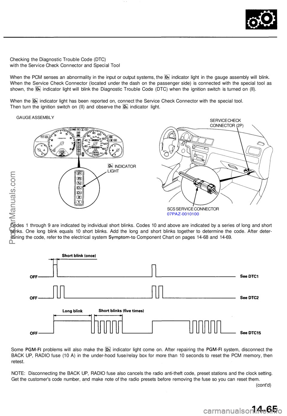
Whe n th e PC M sense s a n abnormalit y i n th e inpu t o r outpu t systems , th e indicato r ligh t i n th e gaug e assembl y wil l blink .
Whe n th e Servic e Chec k Connecto r (locate d unde r th e das h o n th e passenge r side ) i s connecte d wit h th e specia l too l a s
shown , th e indicato r ligh t wil l blin k th e Diagnosti c Troubl e Cod e (DTC ) whe n th e ignitio n switc h i s turne d o n (II) .
Whe n th e indicato r ligh t ha s bee n reporte d on , connec t th e Servic e Chec k Connecto r wit h th e specia l tool .
Then tur n th e ignitio n switc h o n (II ) an d observ e th e indicato r light .
GAUG E ASSEMBL Y
SERVICE CHEC K
CONNECTO R (2P )
INDICATO R
LIGH T
SCS SERVIC E CONNECTO R07PAZ-001010 0
Codes 1 throug h 9 ar e indicate d b y individua l shor t blinks . Code s 1 0 an d abov e ar e indicate d b y a serie s o f lon g an d shor t
blinks . On e lon g blin k equal s 1 0 shor t blinks . Ad d th e lon g an d shor t blink s togethe r t o determin e th e code . Afte r deter -
mining th e code , refe r to th e electrica l syste m Symptom-t o Component Char t o n page s 14-6 8 an d 14-69 .
Some PGM-F I problem s wil l als o mak e th e indicato r ligh t com e on . Afte r repairin g th e PGM-F I system, disconnec t th e
BAC K UP , RADI O fus e (1 0 A ) i n th e under-hoo d fuse/rela y bo x fo r mor e tha n 1 0 second s t o rese t th e PC M memory , the n
retest .
NOTE : Disconnectin g th e BAC K UP , RADI O fus e als o cancel s th e radi o anti-thef t code , prese t station s an d th e cloc k setting .
Ge t th e customer' s cod e number , an d mak e not e o f th e radi o preset s befor e removin g th e fus e s o yo u ca n rese t them .
(cont'd )
ProCarManuals.com
Page 308 of 1771
PCM Reset Procedure
1. Make sure you have the anti-theft code for the radio, then write down the frequencies for the radio's preset buttons.
2. Turn the ignition switch OFF.
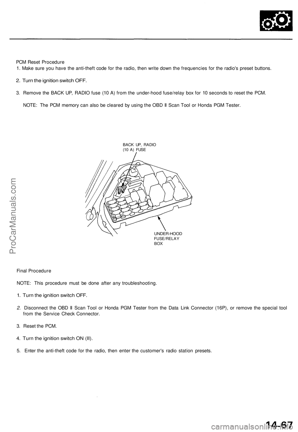
3. Remove the BACK UP, RADIO fuse (10 A) from the under-hood fuse/relay box for 10 seconds to reset the PCM.
NOTE: The PCM memory can also be cleared by using the OBD II Scan Tool or Honda PGM Tester.
BACK UP, RADIO
(10 A) FUSE
UNDER-HOOD
FUSE/RELAY
BOX
Final Procedure
NOTE: This procedure must be done after any troubleshooting.
1. Turn the ignition switch OFF.
2. Disconnect the OBD II Scan Tool or Honda PGM Tester from the Data Link Connector (16P), or remove the special tool
from the Service Check Connector.
3. Reset the PCM.
4. Turn the ignition switch ON (II).
5. Enter the anti-theft code for the radio, then enter the customer's radio station presets.ProCarManuals.com
Page 428 of 1771
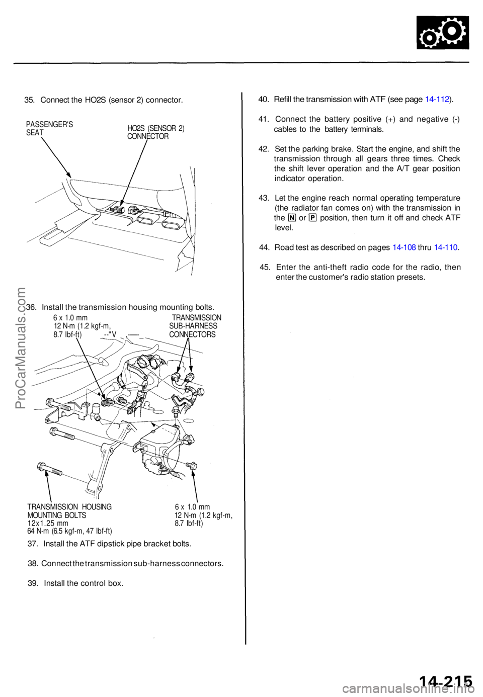
35. Connec t th e HO2 S (senso r 2 ) connector .
PASSENGER' SSEATHO2S (SENSO R 2 )
CONNECTO R
36. Instal l th e transmissio n housin g mountin g bolts .
6 x 1. 0 m m TRANSMISSIO N
1 2 N- m (1. 2 kgf-m , SUB-HARNES S
8. 7 Ibf-ft ) _--" V ,-—- _ CONNECTOR S
TRANSMISSIO N HOUSIN G 6 x 1. 0 m m
MOUNTIN G BOLT S 1 2 N- m (1. 2 kgf-m ,
12x1.2 5 m m 8. 7 Ibf-ft )
6 4 N- m (6. 5 kgf-m , 4 7 Ibf-ft )
37. Instal l th e AT F dipstic k pip e bracke t bolts .
38 . Connec t th e transmissio n sub-harnes s connectors .
39 . Instal l th e contro l box .
40. Refil l th e transmissio n wit h AT F (se e pag e 14-112 ).
41 . Connec t th e batter y positiv e (+ ) an d negativ e (- )
cable s t o th e batter y terminals .
42 . Se t th e parkin g brake . Star t th e engine , an d shif t th e
transmissio n throug h al l gear s thre e times . Chec k
th e shif t leve r operation and th e A/ T gea r positio n
indicato r operation .
43 . Le t th e engin e reac h norma l operatin g temperatur e
(th e radiato r fa n come s on ) wit h th e transmissio n in
th e o r position , the n tur n i t of f an d chec k AT F
level .
44 . Roa d tes t a s describe d o n page s 14-10 8 thr u 14-110 .
45 . Ente r th e anti-thef t radi o cod e fo r th e radio , the n
ente r th e customer' s radi o statio n presets .
ProCarManuals.com
Page 522 of 1771
Troubleshooting Precautions
ABS Indicator Light
1. If the system is OK, the ABS indicator light goes off two seconds after turning the ignition switch ON (II) without start-
ing the engine. After starting the engine, the ABS indicator light comes on again and goes off after two seconds. This
occurs because the ABS control unit is activated by the IG2 power source.
2. The ABS indicator light comes on when the ABS control unit detects a problem in the system. However, even though
the system is normal, the ABS indicator light comes on, too, under the following conditions. To determine the actual
cause of problem, question the customer about the problem, talking the following conditions into consideration.
Only drive wheels rotate
One wheel stuck of drive wheels
Vehicle spin
ABS operate condition continue for long time
Signal disturbance
3. When a problem is detected and the ABS indicator light comes on, there are cases when the indicator light stays on
until the ignition switch is turned OFF, and cases when the indicator light goes off automatically when the system
returns normal. For the DTC 61 and 62, the indicator light goes off automatically when the system returns normal. For
all other codes, the indicator light stays on until the ignition switch is turned OFF.
4. For DTCs 12, 14, 16, 18, 21, 22, 23, 24, 51, 52 and 53, the indicator light goes off when the vehicle is driven again and
the signals are OK after the ignition switch is turned from OFF to ON (II). However, if the DTC is erased, the CPU is
reset and the indicator light goes off right after the engine is started if the signals are OK.
Diagnostic Trouble Code (DTC)
1. The DTC is not memorized if the CPU cannot be activated or the CPU fails and the indicator light comes on.
2. The memory can hold any number of DTCs. However, when the same DTC is detected more than once, the later one
is written over the old one. Therefore, when the same problem is detected repeatedly, it is memorized as one DTC.
3. The DTCs are indicated in the order of ascending number, not in the order they occur.
4. The DTCs are memorized in the EEPROM (non-volatile memory). Therefore, the memorized DTCs cannot be canceled
by disconnecting the battery. Perform the specified procedures to erase the DTCs.
Self-diagnosis
1. The
self-diagnosis
can be
classified
into
two
categories.
• Initial diagnosis: Performed right after the engine starts and until the ABS indicator light goes off.
• Regular diagnosis: Performed right after the initial diagnosis until the ignition switch is turned OFF.
2. When a problem is detected by self-diagnosis, the system
• Turns the ABS indicator light ON
• Memorizes the DTC
• Turns the fail-safe relay OFF
• Stops ABS controlProCarManuals.com
Page 565 of 1771
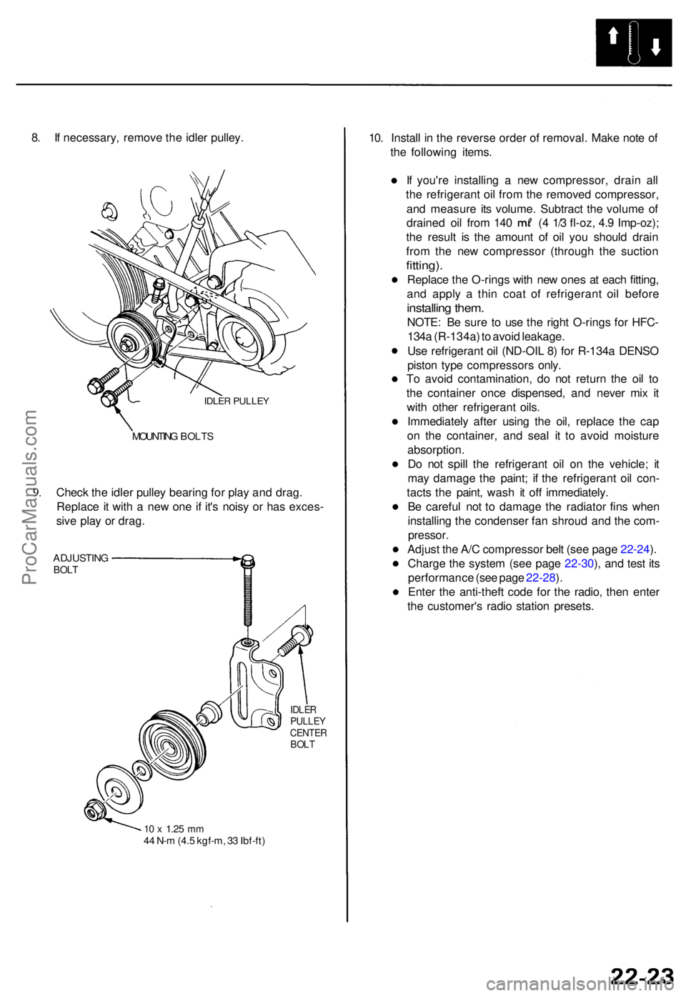
8. I f necessary , remov e th e idle r pulley .
IDLER PULLE Y
9.
MOUNTIN G BOLT S
Check th e idle r pulle y bearin g fo r pla y an d drag .
Replac e it wit h a ne w on e i f it' s nois y o r ha s exces -
siv e pla y o r drag .
ADJUSTIN GBOLT
IDLE RPULLE YCENTE RBOLT
10 x 1.2 5 mm44 N- m (4. 5 kgf-m , 3 3 Ibf-ft )
10. Instal l i n th e revers e orde r o f removal . Mak e not e o f
th e followin g items .
I f you'r e installin g a ne w compressor , drai n al l
th e refrigeran t oi l fro m th e remove d compressor ,
an d measur e it s volume . Subtrac t th e volum e o f
draine d oi l fro m 14 0 ( 4 1/ 3 fl-oz , 4. 9 Imp-oz) ;
th e resul t i s th e amoun t o f oi l yo u shoul d drai n
fro m th e ne w compresso r (throug h th e suctio n
fitting).
Replac e th e O-rings with ne w one s a t eac h fitting ,
an d appl y a thi n coa t of refrigeran t oi l befor e
installin g them .
NOTE : B e sur e t o us e th e righ t O-ring s fo r HFC -
134 a (R-134a ) t o avoi d leakage .
Us e refrigeran t oi l (ND-OI L 8 ) fo r R-134 a DENS O
pisto n typ e compressor s only .
T o avoi d contamination , d o no t retur n th e oi l t o
th e containe r onc e dispensed , an d neve r mi x i t
wit h othe r refrigeran t oils .
Immediatel y afte r usin g th e oil , replac e th e ca p
o n th e container , an d sea l i t t o avoi d moistur e
absorption .
D o no t spil l th e refrigeran t oi l o n th e vehicle ; i t
ma y damag e th e paint ; i f th e refrigeran t oi l con -
tact s th e paint , was h i t of f immediately .
B e carefu l no t t o damag e th e radiato r fin s whe n
installin g th e condense r fa n shrou d an d th e com -
pressor .
Adjust th e A/ C compresso r bel t (se e pag e 22-24 ).
Charg e th e syste m (se e pag e 22-30 ), an d tes t it s
performanc e (se e pag e 22-28 ).
Ente r th e anti-thef t cod e fo r th e radio , the n ente r
th e customer' s radi o statio n presets .
ProCarManuals.com
Page 586 of 1771
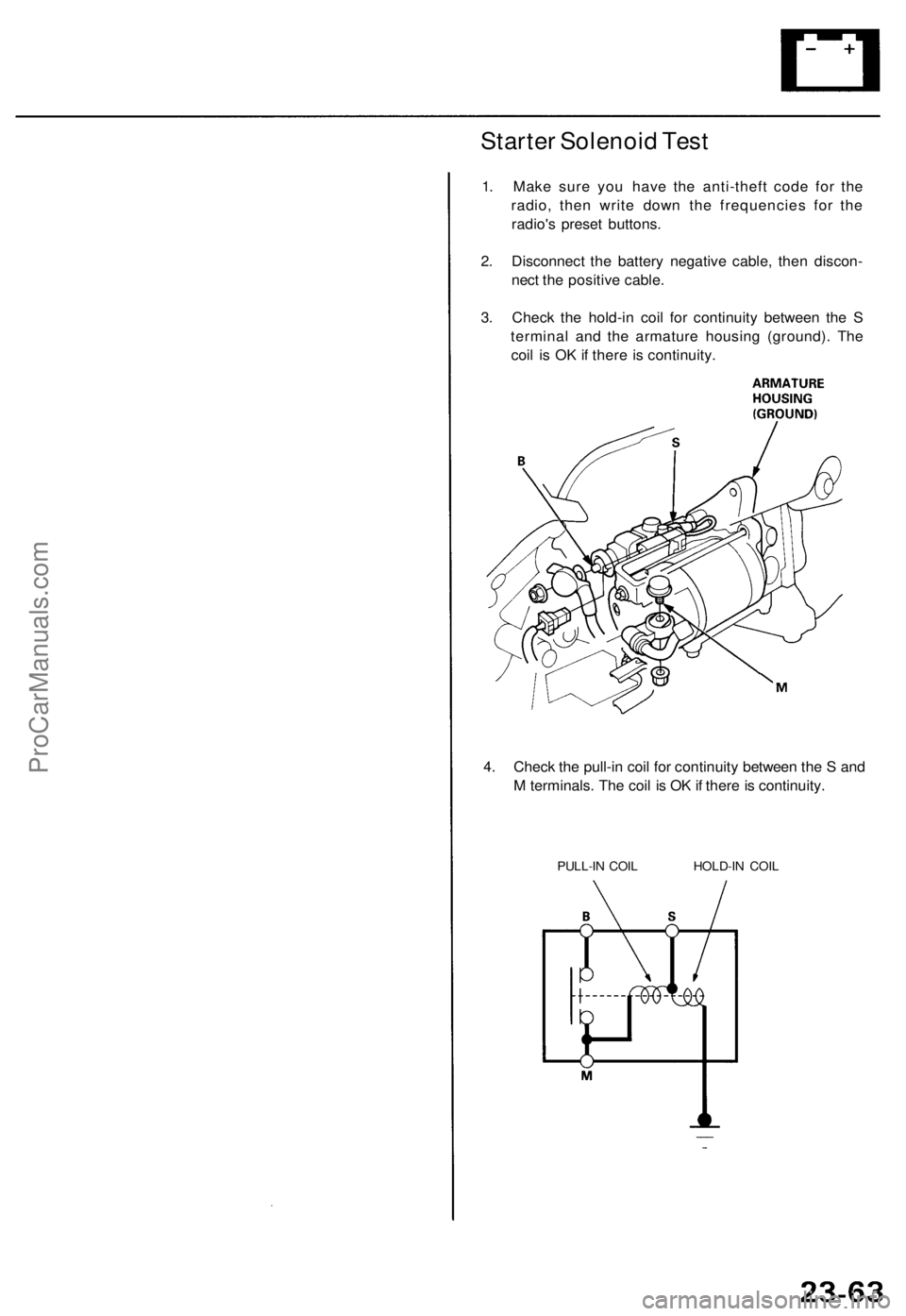
Starter Solenoid Test
1. Make sure you have the anti-theft code for the
radio, then write down the frequencies for the
radio's preset buttons.
2. Disconnect the battery negative cable, then discon-
nect the positive cable.
3. Check the hold-in coil for continuity between the S
terminal and the armature housing (ground). The
coil is OK if there is continuity.
4. Check the pull-in coil for continuity between the S and
M terminals. The coil is OK if there is continuity.
PULL-IN COIL HOLD-IN COILProCarManuals.com
Page 587 of 1771
Starting Syste m
Starter Replacemen t
1. Mak e sur e yo u hav e th e anti-thef t cod e fo r th e radio ,
the n writ e dow n th e frequencie s fo r th e radio' s prese t
buttons .
2 . Disconnec t th e batter y negativ e cable , the n disconnec t
th e positiv e cable .
3 . Remov e th e lef t driv e shaft .
4 . Remov e th e exhaus t pip e A .
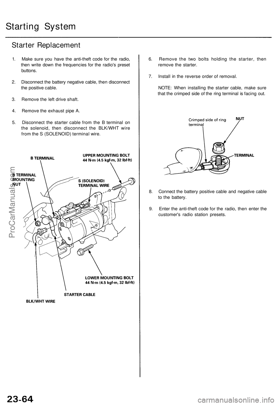
5 . Disconnec t th e starte r cabl e fro m th e B termina l o n
th e solenoid , the n disconnec t th e BLK/WH T wir e
fro m th e S (SOLENOID ) termina l wire . 6
. Remov e th e tw o bolt s holdin g th e starter , the n
remov e th e starter .
7 . Instal l i n th e revers e orde r o f removal .
NOTE : Whe n installin g th e starte r cable , mak e sur e
tha t th e crimpe d sid e o f th e rin g termina l i s facin g out .
8 . Connec t th e batter y positiv e cabl e an d negativ e cabl e
t o th e battery .
9 . Ente r th e anti-thef t cod e fo r th e radio , the n ente r th e
customer' s radi o statio n presets .
ProCarManuals.com
Page 606 of 1771

Alternator Replacemen t
1. Mak e sur e yo u hav e th e anti-thef t cod e fo r th e radio ,
the n writ e dow n th e frequencie s fo r th e radio' s pre -
set buttons .
2. Disconnec t th e batter y negativ e cable , the n discon -
nec t th e positiv e cable .
3 . Remov e th e lowe r mountin g bolt , adjustin g loc k
bol t an d adjustin g rod , the n remov e th e bel t fro m
th e pulley . 4
. A s show n i n th e illustration , rotat e th e alternato r 9 0
degree s counterclockwis e an d pul l i t ou t towar d you .
5 . Disconnec t th e 4 P connecto r an d th e harnes s cli p
bracket , the n remov e th e termina l nu t an d th e BL K
wir e fro m th e B terminal . Tak e ou t th e alternator .
6 . Instal l i n th e revers e orde r o f removal .
7 . Adjus t th e alternato r bel t tensio n (se e pag e 23-89 ).
8 . Ente r th e anti-theft code fo r th e radio , the n ente r th e
customer' s radi o statio n presets .
ProCarManuals.com