Page 1658 of 1771
Removal
1. Mak e sur e yo u hav e th e anti-thef t cod e fo r th e radio ,
the n writ e dow n th e frequencie s fo r th e radio' s pre -
set buttons .
2. Pr y ou t th e dashboar d cente r pane l fro m th e dash -
board .
3 . Disconnec t th e connector s fro m th e climat e contro l
unit.
DASHBOAR D CENTE R PANE L
4. Remov e th e radi o pane l an d stere o radio /
cassette/C D Playe r fro m th e dashboard .
5 . Disconnec t th e 16 P an d 5 P connectors , an d antenn a
lea d fro m th e stere o radio/cassette/C D player .
5PCONNECTO RANTENNALEAD
16 P CONNECTO R
STERE O RADIO/CASSETTE/C D PLAYE R
6. Remov e th e stere o radio/cassette/C D playe r fro m
th e radi o panel .
STERE O RADIO/CASSETTE/C DPLAYER
RADIO PANE L
7. Instal l i n th e revers e orde r o f removal .
8 . Ente r th e anti-thef t cod e fo r th e radio , the n ente r th e
customer' s radi o statio n presets .
ProCarManuals.com
Page 1666 of 1771
Horns
Switc h Tes t (cont'd )
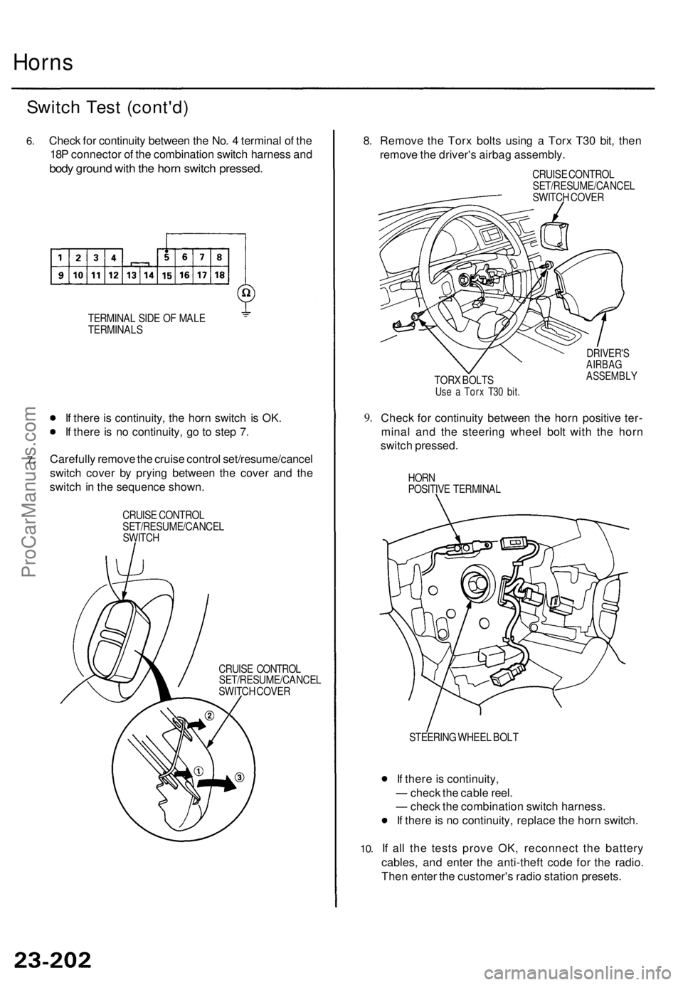
6.Chec k fo r continuit y betwee n th e No . 4 termina l o f th e
18 P connecto r o f th e combinatio n switc h harnes s an d
bod y groun d wit h th e hor n switc h pressed .
TERMINA L SID E O F MAL E
TERMINAL S
7.
If ther e is continuity , th e hor n switc h i s OK .
I f ther e is n o continuity , g o to ste p 7 .
Carefull y remov e th e cruis e contro l set/resume/cance l
switc h cove r b y pryin g betwee n th e cove r an d th e
switc h in th e sequenc e shown .
CRUISE CONTRO L
SET/RESUME/CANCE L
SWITC H
CRUISE CONTRO L
SET/RESUME/CANCE L
SWITC H COVE R
8. Remov e th e Tor x bolt s usin g a Tor x T3 0 bit , the n
remov e th e driver' s airba g assembly .
CRUISE CONTRO L
SET/RESUME/CANCE L
SWITC H COVE R
TOR X BOLT S
Use a Tor x T3 0 bit .
DRIVER' SAIRBAGASSEMBL Y
9.Chec k fo r continuit y betwee n th e hor n positiv e ter -
mina l an d th e steerin g whee l bol t wit h th e hor n
switc h pressed .
HORN
POSITIV E TERMINA L
10.
STEERIN G WHEE L BOL T
If ther e is continuity ,
— chec k th e cabl e reel .
— chec k th e combinatio n switc h harness .
I f ther e is n o continuity , replac e th e hor n switch .
I f al l th e test s prov e OK , reconnec t th e batter y
cables , an d ente r th e anti-thef t cod e fo r th e radio .
The n ente r th e customer' s radi o statio n presets .
ProCarManuals.com
Page 1723 of 1771
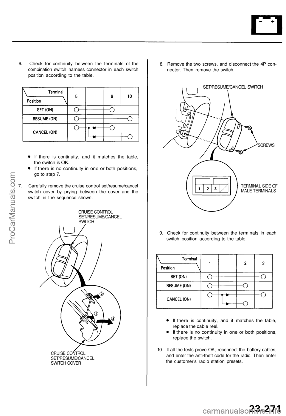
6. Check for continuity between the terminals of the
combination switch harness connector in each switch
position according to the table.
If there is continuity, and it matches the table,
the switch is OK.
If there is no continuity in one or both positions,
go to step 7.
7. Carefully remove the cruise control set/resume/cancel
switch cover by prying between the cover and the
switch in the sequence shown.
CRUISE CONTROL
SET/RESUME/CANCEL
SWITCH
CRUISE CONTROL
SET/RESUME/CANCEL
SWITCH COVER
8. Remove the two screws, and disconnect the 4P con-
nector. Then remove the switch.
SET/RESUME/CANCEL SWITCH
SCREWS
TERMINAL SIDE OF
MALE TERMINALS
9. Check for continuity between the terminals in each
switch position according to the table.
If there is continuity, and it matches the table,
replace the cable reel.
If there is no continuity in one or both positions,
replace the switch.
10. If all the tests prove OK, reconnect the battery cables,
and enter the anti-theft code for the radio. Then enter
the customer's radio station presets.ProCarManuals.com
Page 1762 of 1771
Airbag
Replacemen t (cont'd )
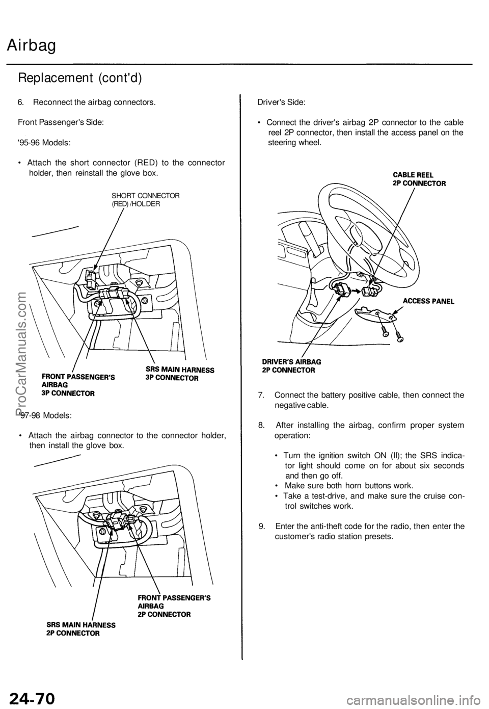
6. Reconnec t th e airba g connectors .
Fron t Passenger' s Side :
'95-9 6 Models :
• Attac h th e shor t connecto r (RED ) t o th e connecto r
holder , the n reinstal l th e glov e box .
SHOR T CONNECTO R(RED) /HOLDE R
'97-98 Models :
• Attac h th e airba g connecto r t o th e connecto r holder ,
the n instal l th e glov e box . Driver'
s Side :
• Connec t th e driver' s airba g 2 P connecto r t o th e cabl e
ree l 2 P connector , the n instal l th e acces s pane l o n th e
steerin g wheel .
7 . Connec t th e batter y positiv e cable , the n connec t th e
negativ e cable .
8 . Afte r installin g th e airbag , confir m prope r syste m
operation :
• Tur n th e ignitio n switc h O N (II) ; th e SR S indica -
to r ligh t shoul d com e o n fo r abou t si x second s
an d the n g o off .
• Mak e sur e bot h hor n button s work .
• Tak e a test-drive , an d mak e sur e th e cruis e con -
tro l switche s work .
9 . Ente r th e anti-thef t cod e fo r th e radio , the n ente r th e
customer' s radi o statio n presets .
ProCarManuals.com
Page 1768 of 1771
Cable Ree l
Replacemen t (cont'd )
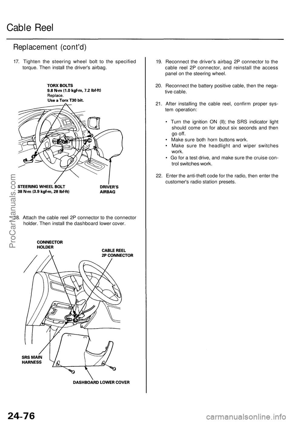
17. Tighte n th e steerin g whee l bol t t o th e specifie d
torque . The n instal l th e driver' s airbag .
18 . Attac h th e cabl e ree l 2 P connecto r t o th e connecto r
holder . The n instal l th e dashboar d lowe r cover . 19
. Reconnec t th e driver' s airba g 2 P connecto r t o th e
cabl e ree l 2 P connector , an d reinstal l th e acces s
pane l o n th e steerin g wheel .
20 . Reconnec t th e batter y positiv e cable , the n th e nega -
tiv e cable .
21 . Afte r installin g th e cabl e reel , confir m prope r sys -
te m operation :
• Tur n th e ignitio n O N (II) ; th e SR S indicato r ligh t
shoul d com e o n fo r abou t si x second s an d the n
go off .
• Mak e sur e bot h hor n button s work .
• Mak e sur e th e headligh t an d wipe r switche s
work .
• G o fo r a tes t drive , an d mak e sur e th e cruis e con -
trol switche s work .
22. Ente r th e anti-thef t cod e fo r th e radio , the n ente r th e
customer' s radi o statio n presets .
ProCarManuals.com
Page 1770 of 1771
SRS Uni t
Replacemen t (cont'd )
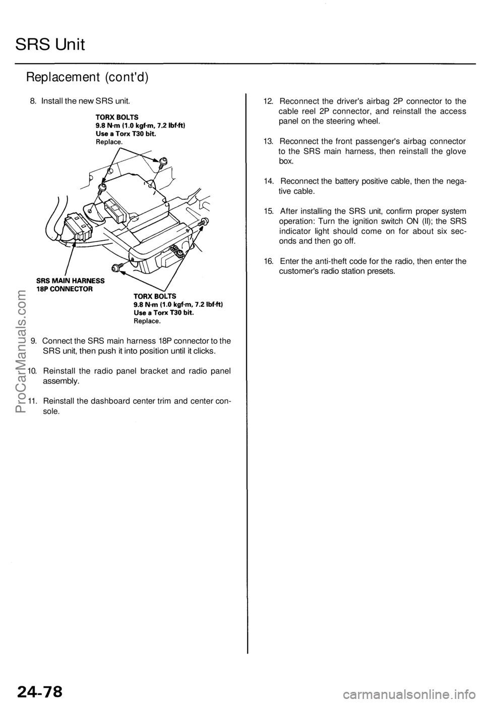
8. Instal l th e ne w SR S unit .
9. Connec t th e SR S mai n harnes s 18 P connecto r t o th e
SR S unit , the n pus h it int o positio n unti l i t clicks .
10. Reinstal l th e radi o pane l bracke t an d radi o pane l
assembly .
11. Reinstal l th e dashboar d cente r tri m an d cente r con -
sole.
12. Reconnec t th e driver' s airba g 2 P connecto r t o th e
cabl e ree l 2 P connector , an d reinstal l th e acces s
pane l o n th e steerin g wheel .
13 . Reconnec t th e fron t passenger' s airba g connecto r
t o th e SR S mai n harness , the n reinstal l th e glov e
box.
14. Reconnec t th e batter y positiv e cable , the n th e nega -
tiv e cable .
15 . Afte r installin g th e SR S unit , confir m prope r syste m
operation : Tur n th e ignitio n switc h O N (II) ; th e SR S
indicato r ligh t shoul d com e o n fo r abou t si x sec -
ond s an d the n g o off .
16 . Ente r th e anti-theft code fo r th e radio , the n ente r th e
customer' s radi o statio n presets .
ProCarManuals.com