1994 JEEP CHEROKEE index
[x] Cancel search: indexPage 446 of 1784

INTERIOR LAMPS
INDEX
page page
Dome Lamp Replacement.................. 20
Dome/Courtesy Lamp Service Information...... 19
Dome/Courtesy Lamp Trouble Diagnosis....... 19
Hardtop Dome/Cargo Lamp Bulb ReplacementÐYJ
Vehicles.............................. 20Illuminated Entry System Service Information . . . 20
Illuminated Entry System Trouble Diagnosis.... 21
Lighted Vanity Mirror...................... 19
Lighted Vanity Mirror Trouble Diagnosis....... 19
Overhead ConsoleÐXJ Vehicles............. 20
DOME/COURTESY LAMP SERVICE INFORMATION
XJ VEHICLES
Voltage is applied at all times via the dome lamp
fuse to each of the interior lamp bulbs. The interior
lamp bulbs illuminate when they are connected to
body ground via the switch:
²headlamp switch,
²glove box switch,
²door pillar switch, and
²liftgate switch (if the cargo lamp is ON.)
If equipped with Security Alarm Module, refer to
Group 8QÐVehicle Theft Security System.
YJ VEHICLES
The dome/cargo and courtesy lamps are controlled
via ON/OFF switches. The ON/OFF switches are in
the lamp ground circuits. Voltage via the dome/cour-
tesy lamp fuse is applied directly to the lamp bulbs.
When either door is opened, the door pillar switch
contacts close and provide a direct path to vehicle
body ground.
The cargo/cargo and courtesy lamps can also be
turned on via the interior lamp illumination rheo-
stat.
DOME/COURTESY LAMP TROUBLE DIAGNOSIS
ALL LAMPS INOPERATIVE
(1) Rotate the headlamp switch rheostat clockwise.
The lamps should light. If not OK, remove, inspect
and test the dome lamp fuse. Replace if bad.
(2) If the fuse is OK, repair the open circuit in the
wire harness to vehicle body ground.
ONE LAMP INOPERATIVE
(1) Measure the resistance across the bulb holder
terminals. The ohmmeter should indicate zero ohms.
If not, replace the bulb.
(2) Measure the voltage between the voltage side
of the bulb holder and vehicle body ground. The volt-
meter should indicate battery voltage. If not, repair
the open circuit in the wire harness to the splice.
LAMPS INOPERATIVE WITH ONE OR MORE
DOORS OPENED
(1) Remove the inoperative switch from the door
pillar and connect the switch wire directly to ground.
The lamp should light.
(2) If not, check for an open circuit in black
(ground) wire. Repair as necessary. If lamps still do
not light, replace the switch.
LIGHTED VANITY MIRROR
SERVICE INFORMATIONÐXJ VEHICLES
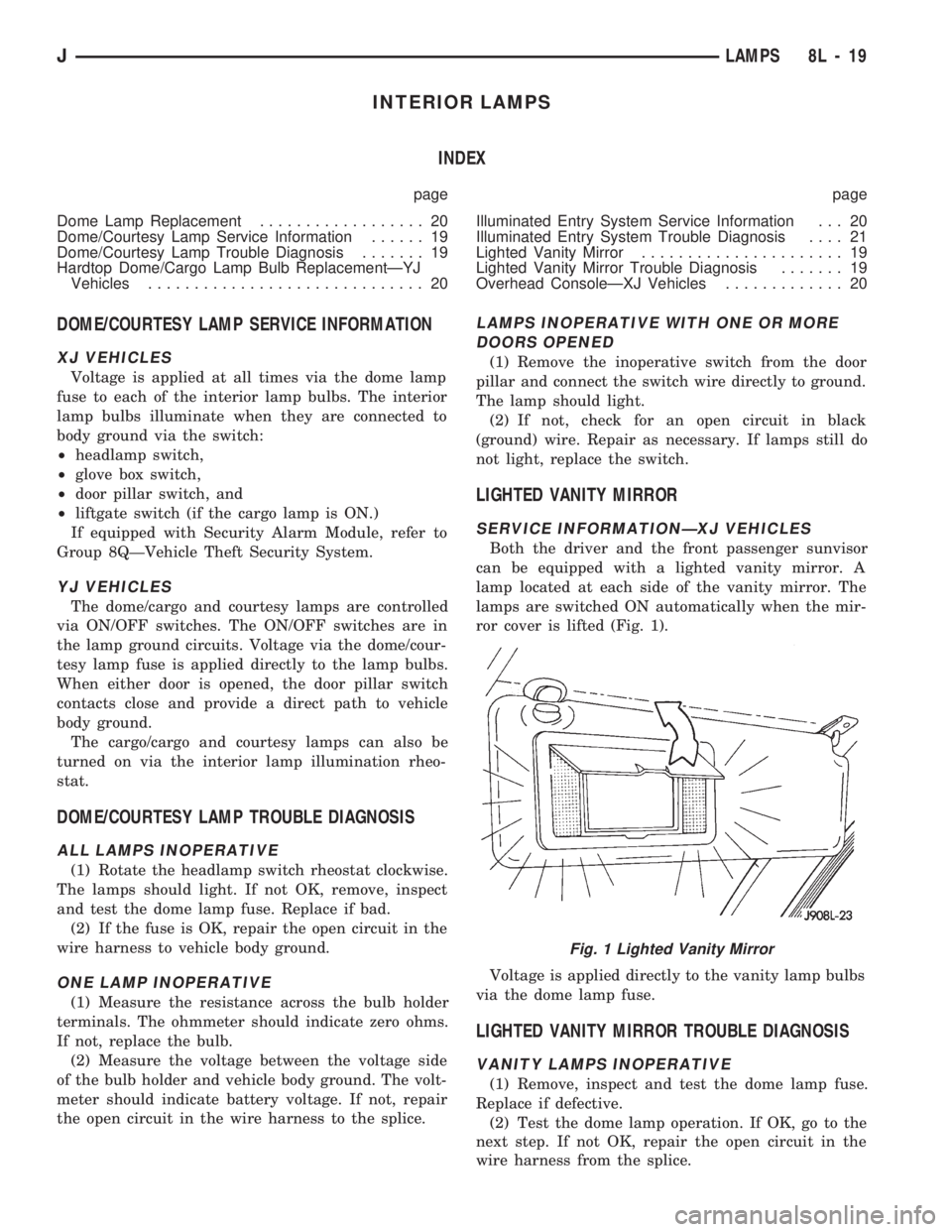
Both the driver and the front passenger sunvisor
can be equipped with a lighted vanity mirror. A
lamp located at each side of the vanity mirror. The
lamps are switched ON automatically when the mir-
ror cover is lifted (Fig. 1).
Voltage is applied directly to the vanity lamp bulbs
via the dome lamp fuse.
LIGHTED VANITY MIRROR TROUBLE DIAGNOSIS
VANITY LAMPS INOPERATIVE
(1) Remove, inspect and test the dome lamp fuse.
Replace if defective.
(2) Test the dome lamp operation. If OK, go to the
next step. If not OK, repair the open circuit in the
wire harness from the splice.
Fig. 1 Lighted Vanity Mirror
JLAMPS 8L - 19
Page 452 of 1784

REAR WINDOW DEFOGGER
CONTENTS
page page
GENERAL.............................. 1
XJ .................................... 4YJ .................................... 4
GENERAL
INDEX
page page
Diagnosis............................... 2
Rear Window Defogger Grid Repair........... 2Rear Window Defogger Grid Test............. 1
Switch Testing............................ 2
Using heating elements bonded to the rear window
glass, the rear defogger will clear condensation, frost
and light snow coverings from the rear window.
The horizontal grid lines and vertical bus bar lines,
printed and baked on inside surface of the rear win-
dow glass, comprise an electrical circuit. The electri-
cally conductive lines are composed of a silver-
ceramic material which when baked on glass
becomes bonded to the glass and is highly resistant
to abrasion.
The electrical current required to produce the heat
in the grid is supplied through a relay and driver op-
erated switch. When the switch is momentarily de-
pressed, the relay senses a voltage change. This
voltage change causes the relay to change state and
complete a circuit to energize the relay. Once the re-
lay energizes, the contacts close connecting the grid
to battery power.
On the XJ, the power circuit to the grid is pro-
tected by the 25 amp, #18 fuse in the fuse box.
Power for fuse #18 comes from the power distribu-
tion center, fuse #F10. Power for the relay is pro-
tected by the 20 amp, #8 fuse located in the fuse box.
On the YJ, the grid is protected by a 25 amp #6
fuse, located in the fuse box. Power for the relay is
protected by 15 amp #9 fuse, located in the fuse box.
To defog the rear window, momentarily depress the
rocker switch. A light on the rocker switch will illu-
minate indicating that the defogger is operating.
If the ignition switch is ON the first activation of
the defog/defrost feature will last for 10 minutes.
Succeeding activations will last for 5 minutes unless
the ignition switch is turned OFF; then it will recy-
cle back to 10 minutes for the first activation.To stop defogger operation, momentarily push the
switch a second time.
CAUTION: Use care when washing the inside of the
rear window to prevent damage to the defogger
heating elements. Use a soft cloth and a mild wash-
ing solution. Wiping motions should be parallel to
the heating elements. Also, keep all objects a safe
distance from the window to prevent damaging the
heating elements.
REAR WINDOW DEFOGGER GRID TEST
It is possible, that a break may exist or occur in an
individual grid line resulting in no current flow
through the line. When a grid has an open circuit,
the area of glass normally cleared by that grid re-
mains fogged or iced unless, and until it is cleared by
the adjacent grids.
With the engine running at idle, push the rear
window defogger switch to the ON position and re-
lease. The pilot lamp in the rocker switch should
light, indicating defogger operation.
Using a 12-volt DC voltmeter, contact the positive
lead to the feed side vertical bus element on the in-
side surface of the glass. Contact the negative lead to
the ground side bus element. Meter should read be-
tween 11 and 13 volts. Connect the negative lead of
the voltmeter to a good ground; the meter reading
should be constant.
Keep the negative lead connected to ground. Use
the positive lead and carefully contact each grid at
the approximate centerline of the window.
JREAR WINDOW DEFOGGER 8N - 1
Page 456 of 1784

POWER DOOR LOCKS
CONTENTS
page page
KEYLESS ENTRY........................ 8POWER LOCKS......................... 1
POWER LOCKS
INDEX
page page
Actuator Motor Stall Test.................... 6
Description.............................. 1
Diagnosing Power Door Locks............... 1
General................................. 1Liftgate Lock Cylinder Replacement............ 7
Solenoid and Latch Assembly Replacement..... 6
Switch Replacement....................... 6
GENERAL
The door lock actuators, including liftgate, are con-
trolled by two-way switches. To lock the doors, push
down on either switch. To unlock doors from inside
the vehicle push upward on either switch.
The power door locks do not lock or unlock the
doors from outside the vehicle. Insert the key into
the lock cylinder to lock or unlock each individual
door.
DESCRIPTION
The door locks are operated by reversible motors
that receive voltage from fuse #13 in the fuse panel.
Voltage is applied to the driver's side door lock
switch and the passenger's side door lock switch
through the #9 fuse. With the driver's side door lock
switch in LOCK, voltage is applied through the
switch to the door lock relay coil. The relay coil is
energized which closes the circuit from the circuit
breaker to the lock motor. The motor is grounded by
the unlock relay.
The passenger's side door lock window switch oper-
ates the same as the driver's door switch. The volt-
age and ground paths are reversed to unlock the
doors.
The power door lock operates with battery power
and, therefore, is independent of the ignition switch.
DIAGNOSING POWER DOOR LOCKS
If vehicle has Keyless Entry and the door locks op-
erate properly using door switches but do not work
with transmitter, refer to Keyless Entry in this
group.
NO DOOR LOCKS OPERATE USING DOOR
LOCK SWITCHES
(1) Inspect fuse #13. Replace if necessary. If OK,
measure voltage at battery side of fuse. There should
be 12 volts. If not, repair open from Power Distribu-
tion Center.
(2) Remove door switch and measure voltage at
terminal 1. Meter should read battery voltage. If not,
repair open to #9 fuse.
(3) The power window relays are in the relay cen-
ter. The relay center is located on the lower instru-
ment panel trim cover just right of the steering
column (Fig. 1). Remove both relays.
(4) Measure resistance between lock and unlock re-
lay terminal 4 (87A) and ground. Meter should read
zero ohms. If not, repair open to ground.
(5) Measure voltage at terminal 5 (87) of both the
lock and unlock relays. Meter should read battery
voltage. If OK, next step. If not, repair open to cir-
cuit breaker.
(6) Measure resistance at terminal 2 (85) of both
the lock and unlock relays. Meter should read zero
ohms. If not, repair open to ground.
(7) Hold driver's side switch in LOCK position.
Measure voltage at lock relay terminal 1 (86). Meter
should read battery voltage. If OK, next step. If not,
repair open to driver's side switch.
(8) Hold driver's side switch in UNLOCK position.
Measure voltage at unlock relay terminal 1 (86).
Meter should read battery voltage. If OK, next step.
If not, repair open to driver's side switch.
JPOWER DOOR LOCKS 8P - 1
Page 463 of 1784

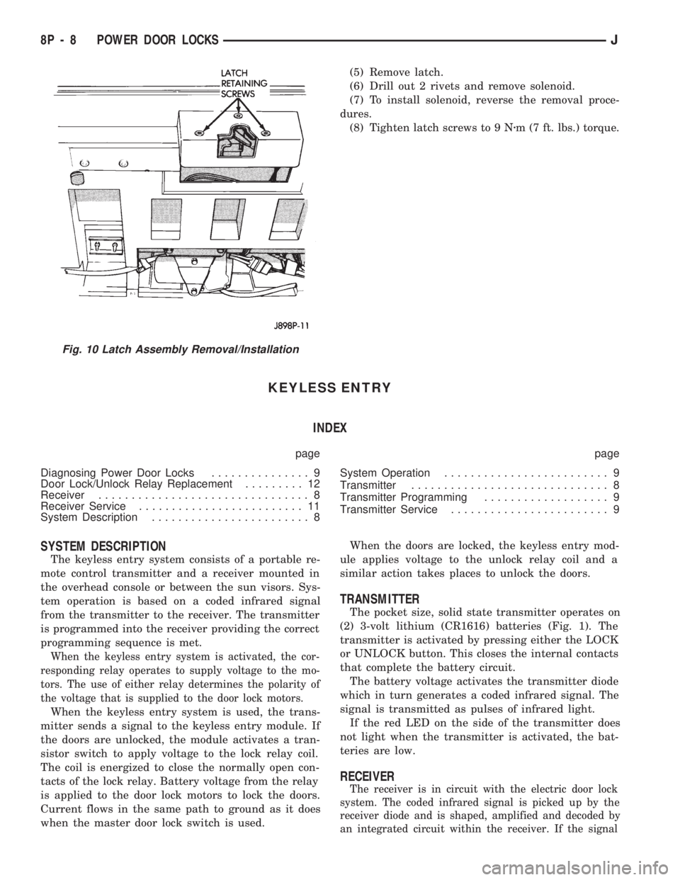
(5) Remove latch.
(6) Drill out 2 rivets and remove solenoid.
(7) To install solenoid, reverse the removal proce-
dures.
(8) Tighten latch screws to 9 Nzm (7 ft. lbs.) torque.
KEYLESS ENTRY
INDEX
page page
Diagnosing Power Door Locks............... 9
Door Lock/Unlock Relay Replacement......... 12
Receiver................................ 8
Receiver Service......................... 11
System Description........................ 8System Operation......................... 9
Transmitter.............................. 8
Transmitter Programming................... 9
Transmitter Service........................ 9
SYSTEM DESCRIPTION
The keyless entry system consists of a portable re-
mote control transmitter and a receiver mounted in
the overhead console or between the sun visors. Sys-
tem operation is based on a coded infrared signal
from the transmitter to the receiver. The transmitter
is programmed into the receiver providing the correct
programming sequence is met.
When the keyless entry system is activated, the cor-
responding relay operates to supply voltage to the mo-
tors. The use of either relay determines the polarity of
the voltage that is supplied to the door lock motors.
When the keyless entry system is used, the trans-
mitter sends a signal to the keyless entry module. If
the doors are unlocked, the module activates a tran-
sistor switch to apply voltage to the lock relay coil.
The coil is energized to close the normally open con-
tacts of the lock relay. Battery voltage from the relay
is applied to the door lock motors to lock the doors.
Current flows in the same path to ground as it does
when the master door lock switch is used.When the doors are locked, the keyless entry mod-
ule applies voltage to the unlock relay coil and a
similar action takes places to unlock the doors.
TRANSMITTER
The pocket size, solid state transmitter operates on
(2) 3-volt lithium (CR1616) batteries (Fig. 1). The
transmitter is activated by pressing either the LOCK
or UNLOCK button. This closes the internal contacts
that complete the battery circuit.
The battery voltage activates the transmitter diode
which in turn generates a coded infrared signal. The
signal is transmitted as pulses of infrared light.
If the red LED on the side of the transmitter does
not light when the transmitter is activated, the bat-
teries are low.
RECEIVER
The receiver is in circuit with the electric door lock
system. The coded infrared signal is picked up by the
receiver diode and is shaped, amplified and decoded by
an integrated circuit within the receiver. If the signal
Fig. 10 Latch Assembly Removal/Installation
8P - 8 POWER DOOR LOCKSJ
Page 494 of 1784

WIRING DIAGRAMS
CONTENTS
page page
FUSE CHARTS AND RELAY BANKS......... 8
GENERAL INFORMATION.................. 1
SPLICE LOCATIONS..................... 53
WIRING AND COMPONENT IDENTIFICATION . 13WIRING DIAGRAMS XJ.................. 149
WIRING DIAGRAMS XJ RHD............. 271
WIRING DIAGRAMS YJ.................. 73
GENERAL INFORMATION
INDEX
page page
Circuit Identification........................ 2
Component Identification.................... 2
Connector and Terminal Assembly Replacement . . 5
Connector Replacement.................... 4
Connectors.............................. 3
Fusible Link Replacement................... 4
Fusible Links............................. 3
Locating A System........................ 2Secondary Ignition Wiring................... 1
Splice Locations.......................... 2
Symbols, Fuses and Abbreviations............ 6
Terminal Replacement...................... 5
Troubleshooting Wiring Problems.............. 3
Wire Code Identification.................... 2
Wiring Diagram Sheets and Indexes........... 1
Wiring Repair............................ 4
The wiring diagrams contain the latest information
at the time of publication.
Throughout this group references may be made to
a particular vehicle by letter or number designation.
A chart showing the breakdown of these designations
is included in the Introduction Section at the front of
this service manual.
SECONDARY IGNITION WIRING
Secondary ignition wiring is shown in Figures 1
and 2. For additional information on ignition systems
or distributor operation refer to Group 8D Ignition
Systems.
WIRING DIAGRAM SHEETS AND INDEXES
The diagrams are organized to show the basic ve-
hicle and all of its options. Add-on or non-factory op-
tions are not covered. The diagram pages are
identified by a sheet number which is located at the
lower right or left hand corner of each sheet.Page
numbers at the top of each page do not apply to
diagram sheets.
Diagram sheets show all information relating to
the system. This includes feeds, grounds, switch in-
ternal circuity, connectors, splices, and pin identifica-
tion for controllers and modules. All components,switches, and relays are shown in the at rest position
with the key removed from the ignition and the doors
closed.
In certain instances a wire may be referenced to
another sheet. When this happens, the wire will be
identified as to where it is going.
The index used for the diagrams is located at the
beginning of the section. The main system and all re-
lated components are covered.
Fig. 1 Secondary Ignition Wiring 2.5L
JWIRING DIAGRAMS 8W - 1
Page 495 of 1784

WIRE CODE IDENTIFICATION
Each wire shown in the diagrams contains a code
(Fig. 3) which identifies the main circuit, part of the
main circuit, gauge of wire, and color. The color is
shown as a two letter code which can be identified by
referring to the Wire Color Code Chart (Fig. 4). If the
wire has a tracer and it is a standard color an aster-
isk will follow the main wire color. If the tracer is
non-standard the main wire color will have a slash (/)
after it followed by the tracer color.
CIRCUIT IDENTIFICATION
All circuits in the diagrams use an alpha/numeric
code to identify the wire and its function. To identify
which circuit code applies to a system, refer to the
Circuit Identification Code Chart. This chart shows
the main circuits only and does not show the second-
ary codes that may apply to some models.
LOCATING A SYSTEM
To locate a system or component in the diagrams,
refer to the alphabetical index at the front of the di-
agrams. Determine the diagram sheet number. Sheet
numbers are located at the lower right or left handcorner of each sheet.Page numbers at the top of
the page do not apply to diagram sheets.
The index identifies the main system and all com-
ponents that relate to that system. There are also
sections of the index that identify specific compo-
nents only (for example modules, lamps, etc.). Refer
to a components name in the index if you are unclear
as to what a system may be called.
Diagram sheets are arranged starting with the bat-
tery and fuses. Then working into charging, starting,
and ignition systems. After this they start at the
front of the vehicle and work to rear. The diagrams
end with connector identification pages.
COMPONENT IDENTIFICATION
When looking for a components location in the vehicle
refer to the Component Identification section index.
This section shows the wire harness routing and the
components location in the vehicle. When using this sec-
tion refer to the wiring diagrams for the general loca-
tion of the component. Then use the component
identification index to locate the proper figure number.
SPLICE LOCATIONS
Splice locations are indicated in the diagrams by a
diamond with a splice circuit code within it (Fig. 5
example 1). If there is more than one splice per cir-
cuit a small box will be connected to it with the
splice number in it (Fig. 5 example 2).
To locate a splice in the wiring harness determine
the splice number from the wiring diagrams then re-
fer to the splice location index. This section shows
the general location of the splice in the harness.
Fig. 2 Secondary Ignition Wiring 4.0L
Fig. 3 Wire Color Code Identification
Fig. 4 Wire Color Code Chart
8W - 2 WIRING DIAGRAMSJ
Page 499 of 1784

(10) Spread the strands of the wire apart on each
of the exposed wires (Fig. 7 example 1).
(11) Push the two ends of wire together until the
strands of wire are close to the insulation (Fig. 7 ex-
ample 2).
(12) Twist the wires together (Fig. 7 example 3).
(13) Solder the connection together using rosin
core type solder only.Do not use acid core solder.
(14) Center the heat shrink tubing over the joint
and heat using a heat gun. Heat the joint until the
tubing is tightly sealed and sealant comes out of both
ends of the tubing.
(15) Insert the repaired wire into the connector.
(16) Install the connector locking wedge and recon-
nect the connector to its mating half.
(17) Re-tape the wire harness starting 1-1/2 inches
behind the connector and 2 inches past the repair.(18) Connect battery and test affected systems.
SYMBOLS, FUSES AND ABBREVIATIONS
Various symbols are used throughout the wiring di-
agrams. These symbols can be identified by referring
to the symbol identification chart (Fig. 11).
Certain abbreviations are also used in the dia-
grams. These have been developed in such a way
that there meaning should be clear. For fuse block,
relay bank, and power distribution center informa-
tion refer to the fuse charts and relay bank index.
CAUTION: When replacing a blown fuse it is impor-
tant to replace it with a fuse having the correct am-
perage rating. The use of a fuse with a rating other
than indicated may result in an electrical overload.
If a proper rated fuse continues to blow, it indicates
a problem that should be corrected.
8W - 6 WIRING DIAGRAMSJ
Page 501 of 1784

FUSE CHARTS AND RELAY BANKS
INDEX
Fig. Fig.
Fuse Panel XJ........................... 2
Fuse Panel YJ........................... 1Power Distribution Center YJ................. 3
Power Distribution Center XJ................. 4
8W - 8 WIRING DIAGRAMSJ