1994 JEEP CHEROKEE index
[x] Cancel search: indexPage 871 of 1784

(12) Properly position the distributor rotor as fol-
lows:
(a) Remove No.1 spark plug. Hold your finger
over the spark plug hole and rotate the crankshaft
until compression pressure is felt. Slowly continue
to rotate the crankshaft until the timing index on
the vibration damper aligns with the top dead cen-
ter (TDC) mark (0É on the timing degree scale).Al-
ways rotate the crankshaft clockwise (the
direction of normal rotation). DO NOT rotate
the crankshaft backward to align the timing
marks.
(b) Rotate the oil pump gear so that the gear slot
on the oil pump shaft is slightly past the 3 o'clock
position (Fig. 12). A flat blade screwdriver can be
used to rotate the gear.
(c) Turn the distributor shaft until the rotor tip
points in the direction of No.1 terminal in the dis-
tributor cap. Turn the rotor 1/8 turn counterclock-
wise past the position of No.1 terminal.
(d) With the distributor cap removed, start the
distributor into the cylinder block with the rotor lo-
cated at the 5 o'clock position (Fig. 13).
(e) Slide the distributor shaft down into the en-
gine. Position the distributor vacuum advance
mechanism housing in approximately the same lo-
cation as when removed. Align the scribe mark onthe distributor housing with the corresponding
scribe mark on the cylinder block. The rotor should
align with the position of No.1 terminal when the
distributor shaft is down in place. It may be neces-
sary to rotate the oil pump shaft with a long flat-
blade screwdriver to engage the oil pump drive
tang.
(f) Install the distributor holddown clamp and
bolt. DO NOT tighten the bolt.
(g) When the distributor is fully engaged in its
correct location, the rotor should be at the 6 o'clock
position (Fig. 14).
(h) If the distributor is not properly installed, or
if it is removed later, then the complete installa-
tion procedures must be repeated.
(13) Install the radiator or radiator/condenser, if
equipped with A/C.
(14) Fill the cooling system.
(15) Connect negative cable to battery.
Fig. 11 Timing Case Cover
Fig. 12 Oil Pump Gear Slot Alignment
Fig. 13 Distributor Rotor Pre-Positioning
Fig. 14 Correct Rotor Position
9 - 30 2.5L ENGINEJ
Page 879 of 1784

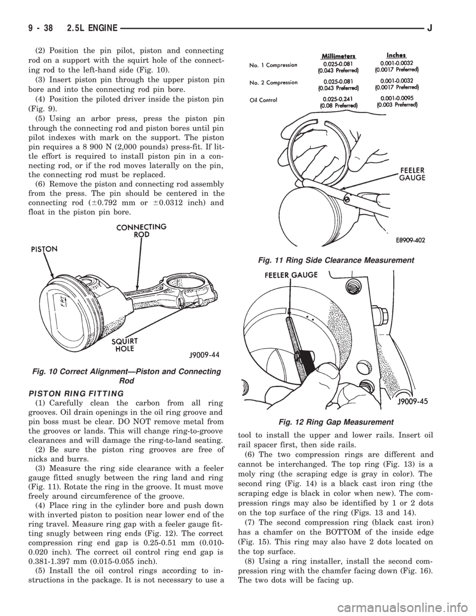
(2) Position the pin pilot, piston and connecting
rod on a support with the squirt hole of the connect-
ing rod to the left-hand side (Fig. 10).
(3) Insert piston pin through the upper piston pin
bore and into the connecting rod pin bore.
(4) Position the piloted driver inside the piston pin
(Fig. 9).
(5) Using an arbor press, press the piston pin
through the connecting rod and piston bores until pin
pilot indexes with mark on the support. The piston
pin requires a 8 900 N (2,000 pounds) press-fit. If lit-
tle effort is required to install piston pin in a con-
necting rod, or if the rod moves laterally on the pin,
the connecting rod must be replaced.
(6) Remove the piston and connecting rod assembly
from the press. The pin should be centered in the
connecting rod (60.792 mm or60.0312 inch) and
float in the piston pin bore.
PISTON RING FITTING
(1) Carefully clean the carbon from all ring
grooves. Oil drain openings in the oil ring groove and
pin boss must be clear. DO NOT remove metal from
the grooves or lands. This will change ring-to-groove
clearances and will damage the ring-to-land seating.
(2) Be sure the piston ring grooves are free of
nicks and burrs.
(3) Measure the ring side clearance with a feeler
gauge fitted snugly between the ring land and ring
(Fig. 11). Rotate the ring in the groove. It must move
freely around circumference of the groove.
(4) Place ring in the cylinder bore and push down
with inverted piston to position near lower end of the
ring travel. Measure ring gap with a feeler gauge fit-
ting snugly between ring ends (Fig. 12). The correct
compression ring end gap is 0.25-0.51 mm (0.010-
0.020 inch). The correct oil control ring end gap is
0.381-1.397 mm (0.015-0.055 inch).
(5) Install the oil control rings according to in-
structions in the package. It is not necessary to use atool to install the upper and lower rails. Insert oil
rail spacer first, then side rails.
(6) The two compression rings are different and
cannot be interchanged. The top ring (Fig. 13) is a
moly ring (the scraping edge is gray in color). The
second ring (Fig. 14) is a black cast iron ring (the
scraping edge is black in color when new). The com-
pression rings may also be identified by 1 or 2 dots
on the top surface of the ring (Figs. 13 and 14).
(7) The second compression ring (black cast iron)
has a chamfer on the BOTTOM of the inside edge
(Fig. 15). This ring may also have 2 dots located on
the top surface.
(8) Using a ring installer, install the second com-
pression ring with the chamfer facing down (Fig. 16).
The two dots will be facing up.
Fig. 10 Correct AlignmentÐPiston and Connecting
Rod
Fig. 11 Ring Side Clearance Measurement
Fig. 12 Ring Gap Measurement
9 - 38 2.5L ENGINEJ
Page 891 of 1784

4.0L ENGINE SERVICE PROCEDURES
INDEX
page page
Camshaft............................... 69
Camshaft Pin Replacement................. 71
Crankshaft Main Bearings.................. 80
Cylinder Block........................... 85
Engine AssemblyÐXJ Vehicles.............. 54
Engine AssemblyÐYJ Vehicles.............. 57
Engine Cylinder Head..................... 60
Engine Cylinder Head Cover................ 59
Engine MountÐRear...................... 52
Engine MountsÐFront..................... 51
General Information....................... 50
Hydraulic Tappets........................ 65
Oil Pan ................................ 72Oil Pump............................... 73
Pistons and Connecting Rods............... 74
Rear Main Oil Seals...................... 84
Rocker Arms............................ 59
Specifications........................... 87
Timing Case Cover....................... 67
Timing Case Cover Oil Seal Replacement...... 67
Timing Chain and Sprockets................ 68
Valve Springs and Oil Seals................ 62
Valve Timing............................ 66
Valves and Valve Springs.................. 63
Vibration Damper........................ 67
GENERAL INFORMATION
The 4.0 Liter (242 CID) six-cylinder engine is an
In-line, lightweight, overhead valve engine (Fig. 1).
This engine is designed for unleaded fuel.
The engine cylinder head has dual quench-type
combustion chambers that create turbulence and fast
burning of the air/fuel mixture. This results in good
fuel economy.
The cylinders are numbered 1 through 6 from front
to rear. The firing order is 1-5-3-6-2-4 (Fig. 2).The crankshaft rotation is clockwise, when viewed
from the front of the engine. The crankshaft rotates
within seven main bearings. The camshaft rotates
within four bearings.
BUILD DATE CODE
The engine Build Date Code is located on a ma-
chined surface on the right side of the cylinder block
between the No.2 and No.3 cylinders (Fig. 3).
The digits of the code identify:
(1) 1st DigitÐThe year (4 = 1994).
(2) 2nd & 3rd DigitsÐThe month (01 - 12).
(3) 4th & 5th DigitsÐThe engine type/fuel system/
compression ratio (MX = A 4.0 Liter (242 CID) 8.7:1
compression ratio engine with a multi-point fuel in-
jection system).
(4) 6th & 7th DigitsÐThe day of engine build (01 -
31).
FOR EXAMPLE:Code * 401MX12 * identifies a
4.0 liter (242 CID) engine with a multi-point fuel in-
jection system, 8.7:1 compression ratio and built on
January 12, 1994.
Fig. 2 Engine Firing Order
Fig. 1 Engine Description
9 - 50 4.0L ENGINEJ
Page 907 of 1784

LEAK-DOWN TEST
After cleaning and inspection, test each tappet for
specified leak-down rate tolerance to ensure zero-lash
operation (Fig. 12).
Swing the weighted arm of the hydraulic valve tap-
pet tester away from the ram of the Leak-Down
Tester 7980.
(1) Place a 7.925-7.950 mm (0.312-0.313 inch) di-
ameter ball bearing on the plunger cap of the tappet.
(2) Lift the ram and position the tappet (with the
ball bearing) inside the tester cup.
(3) Lower the ram, then adjust the nose of the ram
until it contacts the ball bearing. DO NOT tighten
the hex nut on the ram.
(4) Fill the tester cup with hydraulic valve tappet
test oil until the tappet is completely submerged.
(5) Swing the weighted arm onto the push rod and
pump the tappet plunger up and down to remove air.
When the air bubbles cease, swing the weighted arm
away and allow the plunger to rise to the normal po-
sition.
(6) Adjust the nose of the ram to align the pointer
with the SET mark on the scale of the tester and
tighten the hex nut.
(7) Slowly swing the weighted arm onto the push
rod.
(8) Rotate the cup by turning the handle at the
base of the tester clockwise one revolution every 2
seconds.
(9) Observe the leak-down time interval from the
instant the pointer aligns with the START mark on
the scale until the pointer aligns with the 0.125
mark. A normally functioning tappet will require 20-
110 seconds to leak-down. Discard tappets with leak-
down time interval not within this specification.
INSTALLATION
It is not necessary to charge the tappets with en-
gine oil. They will charge themselves within a very
short period of engine operation.(1) Dip each tappet in Mopar Engine Oil Supple-
ment, or equivalent.
(2) Use Hydraulic Valve Tappet Removal/Installa-
tion Tool C-4129-A to install each tappet in the same
bore from where it was originally removed.
(3) Install the exhaust and intake manifolds (refer
to Group 11, Exhaust System and Intake Manifold
for the proper procedure).
(4) Install the engine cylinder head and gasket.
(5) Install the push rods in their original locations.
(6) Install the rocker arms and bridge and pivot
assemblies at their original locations. Loosely install
the capscrews at each bridge.
(7) Tighten the capscrews alternately, one turn at
a time, to avoid damaging the bridges. Tighten the
capscrews to 28 Nzm (21 ft. lbs.) torque.
(8) Pour the remaining Mopar Engine Oil Supple-
ment, or equivalent over the entire valve actuating
assembly. The Mopar Engine Oil Supplement, or
equivalent must remain with the engine oil for at
least 1 609 km (1,000 miles). The oil supplement
need not be drained until the next scheduled oil
change.
(9) Install the engine cylinder head cover.
VALVE TIMING
Disconnect the spark plug wires and remove the
spark plugs.
Remove the engine cylinder head cover.
Remove the capscrews, bridge and pivot assembly,
and rocker arms from above the No.1 cylinder.
Alternately loosen each capscrew, one turn at a
time, to avoid damaging the bridge.
Rotate the crankshaft until the No.6 piston is at
top dead center (TDC) on the compression stroke.
Rotate the crankshaft counterclockwise (viewed
from the front of the engine) 90É.
Install a dial indicator on the end of the No.1 cyl-
inder intake valve push rod. Use rubber tubing to se-
cure the indicator stem on the push rod.
Set the dial indicator pointer at zero.
Rotate the crankshaft clockwise (viewed from the
front of the engine) until the dial indicator pointer
indicates 0.305 mm (0.012 inch) travel distance (lift).
The timing notch index on the vibration damper
should be aligned with the TDC mark on the timing
degree scale.
If the timing notch is more than 13 mm (1/2 inch)
away from the TDC mark in either direction, the
valve timing is incorrect.
If the valve timing is incorrect, the cause may be a
broken camshaft pin. It is not necessary to replace
the camshaft because of pin failure. A spring pin is
available for service replacement.
Fig. 12 Leak-Down Tester 7980
9 - 66 4.0L ENGINEJ
Page 918 of 1784

The difference between cylinder bore diameter and
piston diameter is piston-to-bore clearance.
FEELER GAUGE METHOD
(1) Remove the rings from the piston.
(2) Insert a long 0.025 mm (0.001 inch) feeler
gauge into the cylinder bore.
(3) Insert the piston, top first, into cylinder bore
alongside the feeler gauge. With entire piston in-
serted into cylinder bore, the piston should not bind
against feeler gauge.
(4) Repeat steps with a long 0.051 mm (0.002 inch)
feeler gauge. The piston should bind.
(5) If the piston binds on 0.025 mm (0.001 inch)
feeler gauge, the piston is too large or cylinder bore
is too small. If the piston does not bind on 0.051 mm
(0.002 inch) feeler gauge, the piston is too small for
cylinder bore. Pistons up to 0.102 mm (0.004 inch)
undersize may be enlarged by knurling or shot-peen-
ing. Replace pistons that are 0.102 mm (0.004 inch)
or more undersize.
PISTON PIN
REMOVAL
Piston pins are press-fitted into the connecting rods
and require no locking device.
(1) Position the piston and connecting rod assem-
bly on an arbor press.
(2) Apply force to a piloted driver and press the
pin completely out of the connecting rod and piston
assembly (Fig. 9). Note position of the pin through
the gauge window of removal support tool.INSPECTION
(1) Inspect the piston pin and pin bore in the con-
necting rod for nicks and burrs. Remove as neces-
sary. Never reuse a piston pin after it has been
installed in and removed from a connecting rod.
(2) With the pin removed from the piston and con-
necting rod, clean and dry piston pin bores and the
replacement piston pin.
(3) Position the piston so that the pin bore is in
vertical position. Insert the pin in bore. At room tem-
perature, the replacement pin should slide com-
pletely through the pin bore in piston by force of
gravity.
(4) Replace piston if pin jams in the pin bore.
INSTALLATION
(1) Insert the piston pin pilot through the piston
and connecting rod pin bores. Ensure that the arrow
on the piston crown is pointing up (Fig. 10).
(2) Position the pin pilot, piston and connecting
rod on a support with the squirt hole of the connect-
ing rod to the left-hand side (Fig. 10).
(3) Insert piston pin through the upper piston pin
bore and into the connecting rod pin bore.
(4) Position the piloted driver inside the piston pin
(Fig. 9).
(5) Using an arbor press, press the piston pin
through the connecting rod and piston bores until pin
pilot indexes with mark on the support. The piston
pin requires a 8 900 N (2,000 pounds) press-fit. If lit-
tle effort is required to install piston pin in a con-
necting rod, or if the rod moves laterally on the pin,
the connecting rod must be replaced.
Fig. 8 Piston Dimensions
Fig. 9 Piston Pin Removal/Installation
J4.0L ENGINE 9 - 77
Page 934 of 1784

SERVICE PROCEDURES
INDEX
page page
Catalytic Converter........................ 5
Engine Exhaust ManifoldÐ2.5L Engine......... 7
Engine Exhaust ManifoldÐ4.0L Engine......... 7
Exhaust PipeÐXJ Vehicles.................. 3
Exhaust PipeÐYJ Vehicles.................. 4Intake ManifoldÐ2.5L Engine................ 8
Intake ManifoldÐ4.0L Engine................ 9
Muffler and Exhaust TailpipeÐXJ Vehicles...... 5
Muffler and Exhaust TailpipeÐYJ Vehicles...... 6
EXHAUST PIPEÐXJ VEHICLES
WARNING: IF TORCHES ARE USED WHEN WORK-
ING ON THE EXHAUST SYSTEM, DO NOT ALLOW
THE FLAME NEAR THE FUEL LINES.
REMOVAL
(1) Raise and support the vehicle.
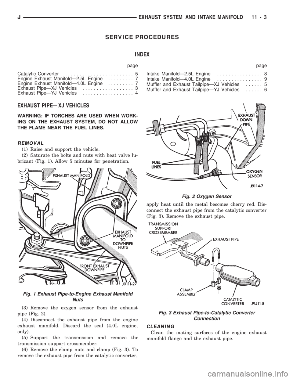
(2) Saturate the bolts and nuts with heat valve lu-
bricant (Fig. 1). Allow 5 minutes for penetration.
(3) Remove the oxygen sensor from the exhaust
pipe (Fig. 2).
(4) Disconnect the exhaust pipe from the engine
exhaust manifold. Discard the seal (4.0L engine,
only).
(5) Support the transmission and remove the
transmission support crossmember.
(6) Remove the clamp nuts and clamp (Fig. 3). To
remove the exhaust pipe from the catalytic converter,apply heat until the metal becomes cherry red. Dis-
connect the exhaust pipe from the catalytic converter
(Fig. 3). Remove the exhaust pipe.
CLEANING
Clean the mating surfaces of the engine exhaust
manifold flange and the exhaust pipe.
Fig. 1 Exhaust Pipe-to-Engine Exhaust Manifold
Nuts
Fig. 2 Oxygen Sensor
Fig. 3 Exhaust Pipe-to-Catalytic Converter
Connection
JEXHAUST SYSTEM AND INTAKE MANIFOLD 11 - 3
Page 942 of 1784

FRAME AND BUMPERS
CONTENTS
page page
XJ BUMPERS........................... 3
XJ UNIBODY CONSTRUCTION............. 1YJ BUMPERS AND FRAME ATTACHED
COMPONENTS........................ 14
YJ FRAME............................. 8
XJ UNIBODY CONSTRUCTION
INDEX
page page
Collision Damage Torque................... 1General Information........................ 1
GENERAL INFORMATION
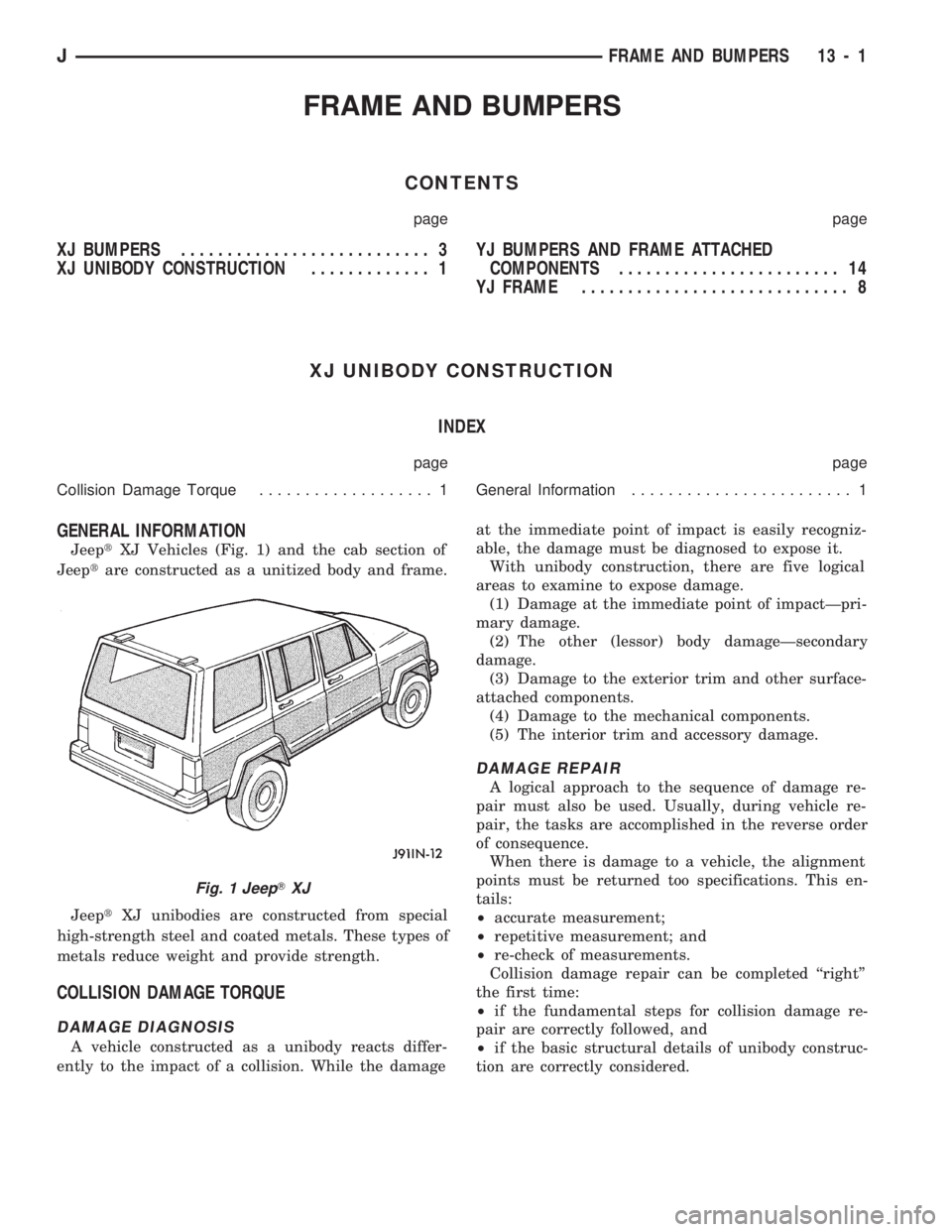
JeeptXJ Vehicles (Fig. 1) and the cab section of
Jeeptare constructed as a unitized body and frame.
JeeptXJ unibodies are constructed from special
high-strength steel and coated metals. These types of
metals reduce weight and provide strength.
COLLISION DAMAGE TORQUE
DAMAGE DIAGNOSIS
A vehicle constructed as a unibody reacts differ-
ently to the impact of a collision. While the damageat the immediate point of impact is easily recogniz-
able, the damage must be diagnosed to expose it.
With unibody construction, there are five logical
areas to examine to expose damage.
(1) Damage at the immediate point of impactÐpri-
mary damage.
(2) The other (lessor) body damageÐsecondary
damage.
(3) Damage to the exterior trim and other surface-
attached components.
(4) Damage to the mechanical components.
(5) The interior trim and accessory damage.
DAMAGE REPAIR
A logical approach to the sequence of damage re-
pair must also be used. Usually, during vehicle re-
pair, the tasks are accomplished in the reverse order
of consequence.
When there is damage to a vehicle, the alignment
points must be returned too specifications. This en-
tails:
²accurate measurement;
²repetitive measurement; and
²re-check of measurements.
Collision damage repair can be completed ``right''
the first time:
²if the fundamental steps for collision damage re-
pair are correctly followed, and
²if the basic structural details of unibody construc-
tion are correctly considered.
Fig. 1 JeepTXJ
JFRAME AND BUMPERS 13 - 1
Page 944 of 1784

XJ BUMPERS
INDEX
page page
Front Bumper............................ 3
Front Tow Hooks......................... 5Rear Bumper............................ 6
FRONT BUMPER
REMOVAL/DISASSEMBLY
(1) The bumper guards, end caps and tow hooks
can be removed from XJ front bumpers with the
bumper attached to the vehicle. Do not remove the
bumper from the vehicle if only these components re-
quire service.
If equipped with a brush guard, refer to the
Brush Guard Removal within Group 23ÐBody
Components.
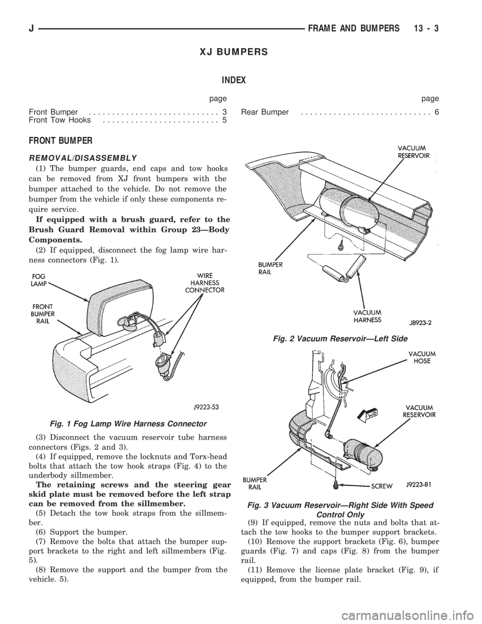
(2) If equipped, disconnect the fog lamp wire har-
ness connectors (Fig. 1).
(3) Disconnect the vacuum reservoir tube harness
connectors (Figs. 2 and 3).
(4) If equipped, remove the locknuts and Torx-head
bolts that attach the tow hook straps (Fig. 4) to the
underbody sillmember.
The retaining screws and the steering gear
skid plate must be removed before the left strap
can be removed from the sillmember.
(5) Detach the tow hook straps from the sillmem-
ber.
(6) Support the bumper.
(7) Remove the bolts that attach the bumper sup-
port brackets to the right and left sillmembers (Fig.
5).
(8) Remove the support and the bumper from the
vehicle. 5).(9) If equipped, remove the nuts and bolts that at-
tach the tow hooks to the bumper support brackets.
(10) Remove the support brackets (Fig. 6), bumper
guards (Fig. 7) and caps (Fig. 8) from the bumper
rail.
(11) Remove the license plate bracket (Fig. 9), if
equipped, from the bumper rail.
Fig. 1 Fog Lamp Wire Harness Connector
Fig. 2 Vacuum ReservoirÐLeft Side
Fig. 3 Vacuum ReservoirÐRight Side With Speed
Control Only
JFRAME AND BUMPERS 13 - 3