1994 JEEP CHEROKEE index
[x] Cancel search: indexPage 1219 of 1784
30RH/32RH TRANSMISSION REMOVAL AND INSTALLATION
INDEX
page page
ConverterÐPump SealÐDrive Plate Service . . . 109
Transmission and Converter Installation....... 109Transmission and Converter Removal........ 108
TRANSMISSION AND CONVERTER REMOVAL
(1) Remove fan shroud attaching bolts.
(2) Disconnect transmission fill tube at upper
bracket.
(3) Raise vehicle.
(4) Remove inspection cover from converter hous-
ing and remove skid plate for access, if necessary.
(5) Remove transmission fill tube and fill tube
O-ring.
(6) Remove starter motor.
(7) Mark propeller shafts and axle yokes for align-
ment reference.
(8) Disconnect propeller shafts at yokes. Secure
shafts to frame rails with wire.
(9) Disconnect exhaust pipes at exhaust manifolds,
if necessary.
(10) Drain transfer case lubricant.
(11) Disconnect vehicle speed sensor wires.
(12) Disconnect transfer case shift linkage.
(13) Disconnect gearshift linkage and throttle ca-
ble at transmission levers.
(14) Disconnect park/neutral position switch wires.
(15) Disconnect and remove crankshaft position
sensor. Retain sensor bolt for reinstallation.
CAUTION: The crankshaft position sensor can be
damaged during transmission removal (or installa-
tion) if the sensor is still bolted to the engine block.
To avoid damage, remove the sensor before remov-
ing the transmission.
(16) Remove converter housing access cover and
mark drive plate and converter for alignment refer-
ence.
(17) Remove bolts attaching converter to drive
plate.
(18) Support engine with support stand.
(19) Support transmission-transfer case assembly
with transmission jack. Secure transmission to jack
with safety chain.
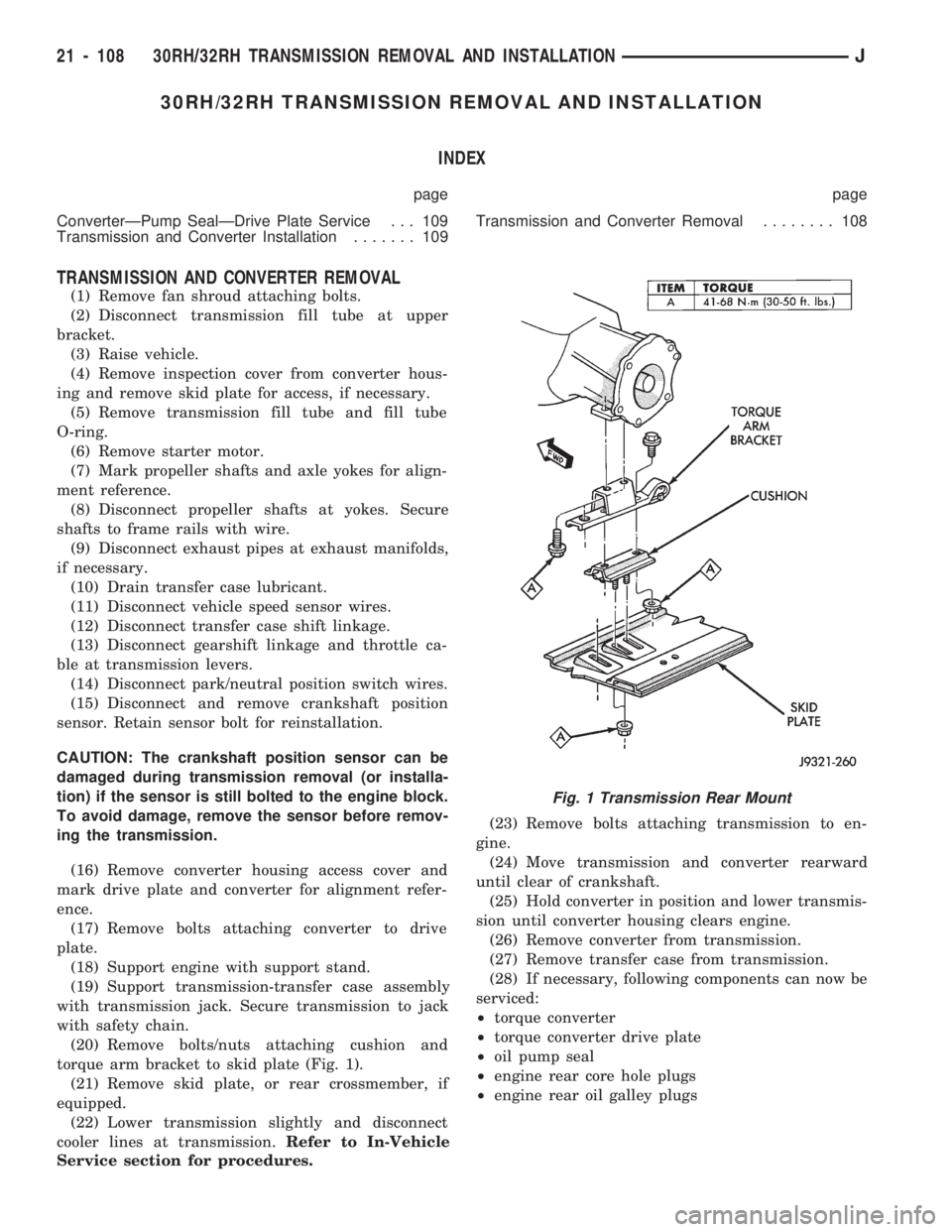
(20) Remove bolts/nuts attaching cushion and
torque arm bracket to skid plate (Fig. 1).
(21) Remove skid plate, or rear crossmember, if
equipped.
(22) Lower transmission slightly and disconnect
cooler lines at transmission.Refer to In-Vehicle
Service section for procedures.(23) Remove bolts attaching transmission to en-
gine.
(24) Move transmission and converter rearward
until clear of crankshaft.
(25) Hold converter in position and lower transmis-
sion until converter housing clears engine.
(26) Remove converter from transmission.
(27) Remove transfer case from transmission.
(28) If necessary, following components can now be
serviced:
²torque converter
²torque converter drive plate
²oil pump seal
²engine rear core hole plugs
²engine rear oil galley plugs
Fig. 1 Transmission Rear Mount
21 - 108 30RH/32RH TRANSMISSION REMOVAL AND INSTALLATIONJ
Page 1223 of 1784
30RH/32RH TRANSMISSION OVERHAUL
INDEX
page page
Adapter Housing and Park Lock Component
Overhaul............................ 120
Front Clutch Overhaul.................... 125
Front Servo and Band Overhaul............ 136
Governor and Park Gear Overhaul.......... 121
Oil Pump Overhaul...................... 122
Overhaul Service Information............... 118
Overrunning ClutchÐLow-Reverse DrumÐRear
Support Overhaul...................... 118
Planetary Gear Train Overhaul............. 131Rear Clutch Overhaul.................... 128
Rear Servo and Band Overhaul............. 136
Transmission Assembly and Adjustment
Procedures........................... 146
Transmission Assembly Tips............... 146
Transmission Case Cleaning and Inspection . . . 118
Transmission Disassembly................. 112
Valve Body Assembly and Adjustment........ 144
Valve Body Disassembly and Inspection...... 138
TRANSMISSION DISASSEMBLY
(1) Clean transmission exterior with steam gun or
with solvent. Wear eye protection during cleaning
process.
(2) Remove throttle and shift levers from valve
body manual shaft and throttle lever shaft.
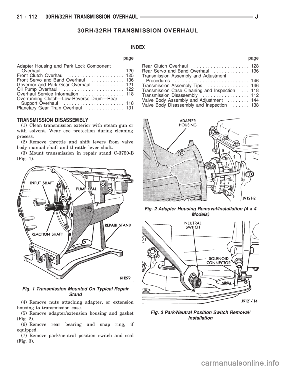
(3) Mount transmission in repair stand C-3750-B
(Fig. 1).
(4) Remove nuts attaching adapter, or extension
housing to transmission case.
(5) Remove adapter/extension housing and gasket
(Fig. 2).
(6) Remove rear bearing and snap ring, if
equipped.
(7) Remove park/neutral position switch and seal
(Fig. 3).
Fig. 1 Transmission Mounted On Typical Repair
Stand
Fig. 2 Adapter Housing Removal/Installation (4 x 4
Models)
Fig. 3 Park/Neutral Position Switch Removal/
Installation
21 - 112 30RH/32RH TRANSMISSION OVERHAULJ
Page 1231 of 1784
before final assembly, install cam only as de-
scribed in Transmission Assembly And Adjust-
ment section. Clutch cam must be properly
indexed in case to fit and operate properly.
ADAPTER HOUSING AND PARK LOCK
COMPONENT OVERHAUL
Clean the housing and park lock components in
solvent and dry them with compressed air.
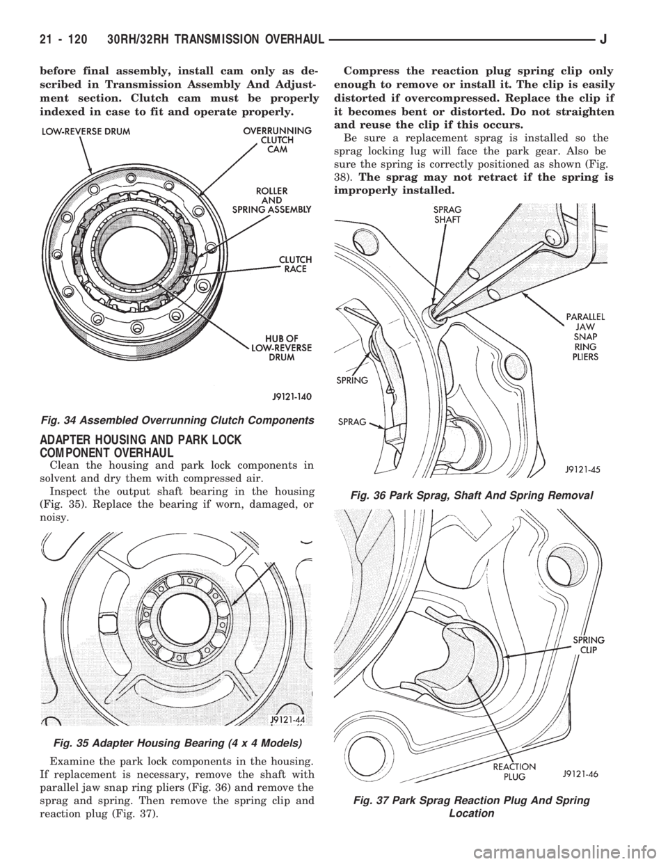
Inspect the output shaft bearing in the housing
(Fig. 35). Replace the bearing if worn, damaged, or
noisy.
Examine the park lock components in the housing.
If replacement is necessary, remove the shaft with
parallel jaw snap ring pliers (Fig. 36) and remove the
sprag and spring. Then remove the spring clip and
reaction plug (Fig. 37).Compress the reaction plug spring clip only
enough to remove or install it. The clip is easily
distorted if overcompressed. Replace the clip if
it becomes bent or distorted. Do not straighten
and reuse the clip if this occurs.
Be sure a replacement sprag is installed so the
sprag locking lug will face the park gear. Also be
sure the spring is correctly positioned as shown (Fig.
38).The sprag may not retract if the spring is
improperly installed.
Fig. 34 Assembled Overrunning Clutch Components
Fig. 35 Adapter Housing Bearing (4 x 4 Models)
Fig. 36 Park Sprag, Shaft And Spring Removal
Fig. 37 Park Sprag Reaction Plug And Spring
Location
21 - 120 30RH/32RH TRANSMISSION OVERHAULJ
Page 1232 of 1784
GOVERNOR AND PARK GEAR OVERHAUL
GOVERNOR/PARK GEAR DISASSEMBLY
(1) Loosen bolts attaching governor to park gear.
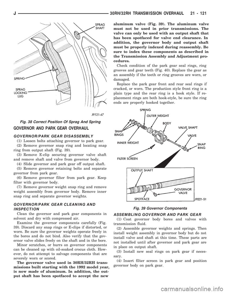
(2) Remove governor snap ring and locating snap
ring from output shaft (Fig. 39).
(3) Remove E-clip securing governor valve shaft
and remove shaft and valve from governor body.
(4) Slide governor and park gear off output shaft.
(5) Remove governor retaining bolts and separate
governor from park gear.
(6) Remove governor filter from park gear. Keep
filter with governor body.
(7) Remove governor weight snap ring and remove
weight assembly from governor body. Remove inner
snap ring and separate governor weights.
GOVERNOR/PARK GEAR CLEANING AND
INSPECTION
Clean the governor and park gear components in
solvent and dry with compressed air.
Examine the governor components carefully (Fig.
39). Discard any snap rings or E-clips if distorted, or
worn. Be sure the governor weights operate freely in
the bores and do not bind. Also verify that the gov-
ernor valve slides freely on the shaft and in the bore.
Minor scratches, or burrs on governor components
can be cleaned up with oil-soaked crocus cloth. How-
ever, do not attempt to salvage components that are
severely worn or scored.
The governor valve used in 30RH/32RH trans-
missions built starting with the 1992 model year,
is now made of aluminum. In addition, the out-
put shaft has been spotfaced to accept the newaluminum valve (Fig. 39). The aluminum valve
must not be used in prior transmissions. The
valve can only be used with an output shaft that
has been spotfaced for valve end clearance. In
addition, the governor body and output shaft
must be properly indexed during reassembly. Be
sure to index these components as described in
the Transmission Assembly and Adjustment pro-
cedures.
Check condition of the park gear seal rings, ring
grooves and gear teeth (Fig. 40). Replace the gear as
an assembly if the teeth or ring grooves are worn, or
damaged.
Replace the park gear front and rear seal rings if
cracked, or worn. The production style front ring is a
plain type and the rear ring is a hook style. If re-
placement rings are both hook-style, be sure the ring
ends are properly hooked together.ASSEMBLING GOVERNOR AND PARK GEAR
(1) Coat governor body bores and valves with
transmission fluid.
(2) Assemble governor weights and springs. Then
install weight assembly in governor body but do not
install valve and shaft at this time. These parts are
not installed until after governor and park gear are
in place on output shaft.
(3) Install new seal rings on park gear if neces-
sary.
(4) Insert filter screen in park gear and position
governor body on park gear.
Fig. 38 Correct Position Of Sprag And Spring
Fig. 39 Governor Components
J30RH/32RH TRANSMISSION OVERHAUL 21 - 121
Page 1261 of 1784
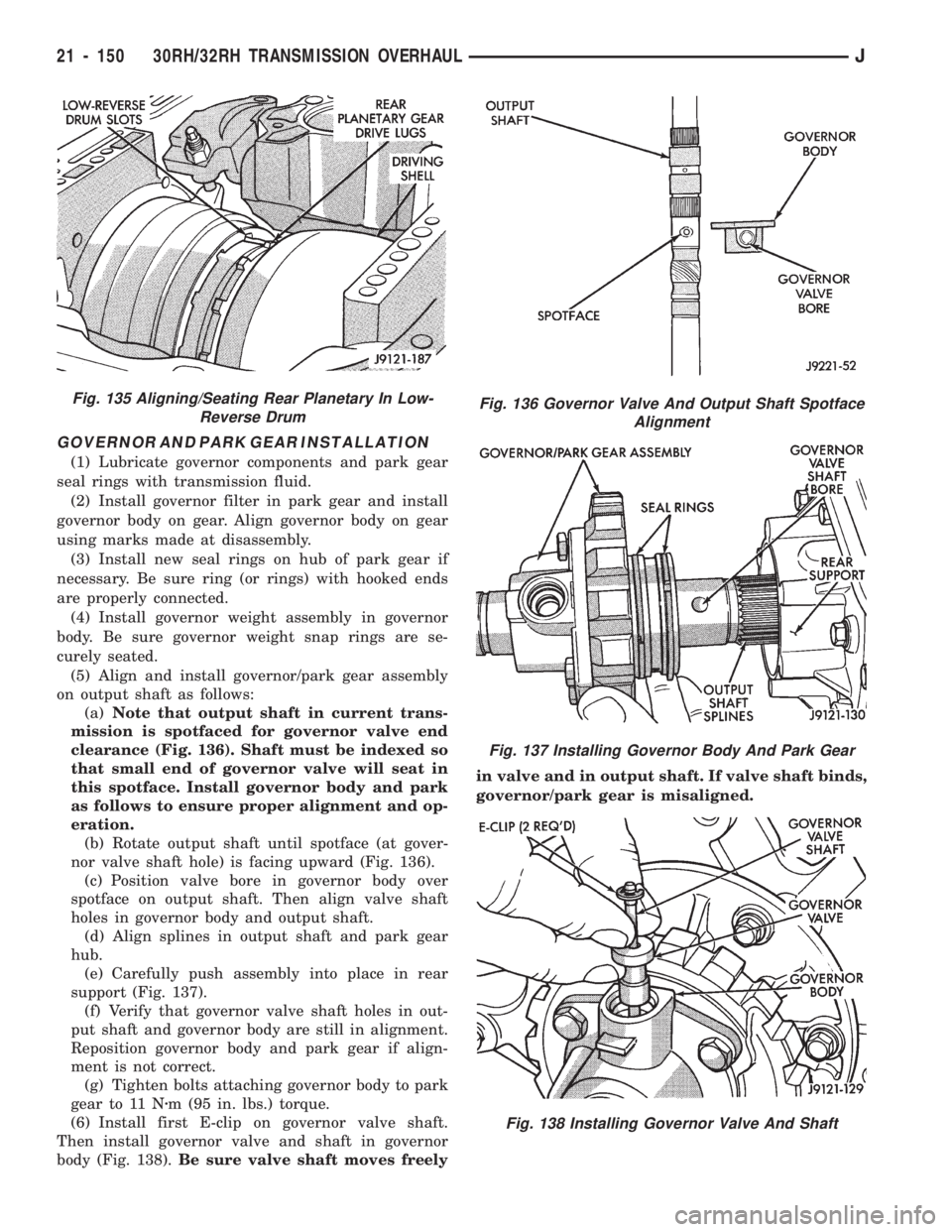
GOVERNOR AND PARK GEAR INSTALLATION
(1) Lubricate governor components and park gear
seal rings with transmission fluid.
(2) Install governor filter in park gear and install
governor body on gear. Align governor body on gear
using marks made at disassembly.
(3) Install new seal rings on hub of park gear if
necessary. Be sure ring (or rings) with hooked ends
are properly connected.
(4) Install governor weight assembly in governor
body. Be sure governor weight snap rings are se-
curely seated.
(5) Align and install governor/park gear assembly
on output shaft as follows:
(a)Note that output shaft in current trans-
mission is spotfaced for governor valve end
clearance (Fig. 136). Shaft must be indexed so
that small end of governor valve will seat in
this spotface. Install governor body and park
as follows to ensure proper alignment and op-
eration.
(b) Rotate output shaft until spotface (at gover-
nor valve shaft hole) is facing upward (Fig. 136).
(c) Position valve bore in governor body over
spotface on output shaft. Then align valve shaft
holes in governor body and output shaft.
(d) Align splines in output shaft and park gear
hub.
(e) Carefully push assembly into place in rear
support (Fig. 137).
(f) Verify that governor valve shaft holes in out-
put shaft and governor body are still in alignment.
Reposition governor body and park gear if align-
ment is not correct.
(g) Tighten bolts attaching governor body to park
gear to 11 Nzm (95 in. lbs.) torque.
(6) Install first E-clip on governor valve shaft.
Then install governor valve and shaft in governor
body (Fig. 138).Be sure valve shaft moves freelyin valve and in output shaft. If valve shaft binds,
governor/park gear is misaligned.
Fig. 136 Governor Valve And Output Shaft Spotface
Alignment
Fig. 137 Installing Governor Body And Park Gear
Fig. 138 Installing Governor Valve And Shaft
Fig. 135 Aligning/Seating Rear Planetary In Low-
Reverse Drum
21 - 150 30RH/32RH TRANSMISSION OVERHAULJ
Page 1267 of 1784
AW-4 AUTOMATIC TRANSMISSION
CONTENTS
page page
AW-4 IN-VEHICLE SERVICE............. 173
AW-4 TRANSMISSION DIAGNOSIS........ 167
AW-4 TRANSMISSION OVERHAUL........ 192
AW-4 TRANSMISSION REMOVAL AND
INSTALLATION....................... 189GENERAL INFORMATION................ 156
TRANSMISSION/TRANSFER CASE
SPECIFICATIONS..................... 320
GENERAL INFORMATION
INDEX
page page
Components and Operation................ 157
Description............................ 156
FirstÐThirdÐReverse Gear Components...... 159
Fourth Gear Overdrive Components......... 158
Geartrain Operation and Application Charts.... 159Hydraulic System........................ 160
Torque Converter........................ 158
Transmission Identification................. 157
Transmission Ranges and Shift Lever Positions . 157
DESCRIPTION
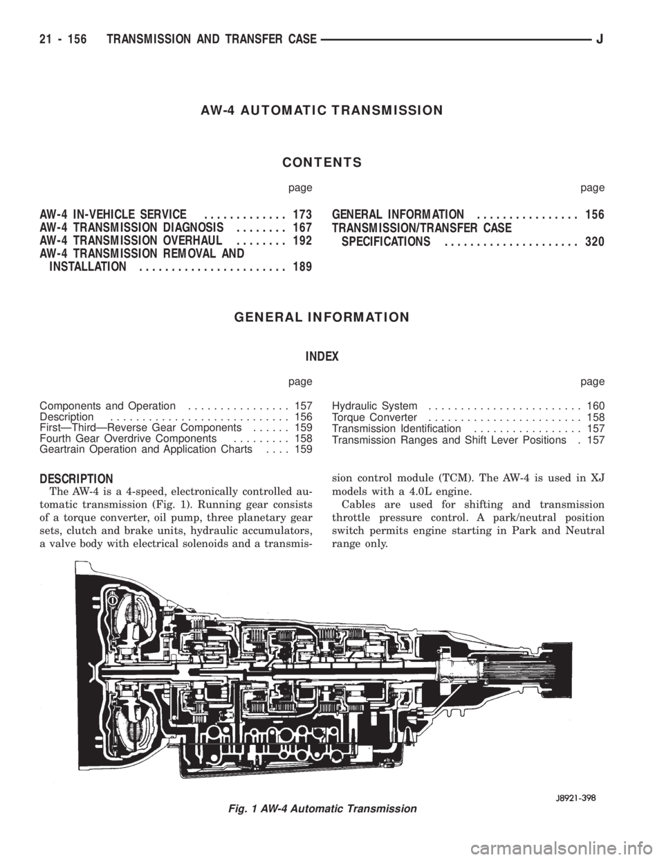
The AW-4 is a 4-speed, electronically controlled au-
tomatic transmission (Fig. 1). Running gear consists
of a torque converter, oil pump, three planetary gear
sets, clutch and brake units, hydraulic accumulators,
a valve body with electrical solenoids and a transmis-sion control module (TCM). The AW-4 is used in XJ
models with a 4.0L engine.
Cables are used for shifting and transmission
throttle pressure control. A park/neutral position
switch permits engine starting in Park and Neutral
range only.
Fig. 1 AW-4 Automatic Transmission
21 - 156 TRANSMISSION AND TRANSFER CASEJ
Page 1278 of 1784
AW-4 TRANSMISSION DIAGNOSIS
INDEX
page page
General Diagnosis Information.............. 167
Hydraulic Pressure Test................... 168
Manual Shifting Test..................... 168Preliminary Inspection and Adjustment........ 167
Time Lag Test .......................... 169
Torque Converter Stall Test................ 169
GENERAL DIAGNOSIS INFORMATION
Shift points are controlled by the transmission con-
trol module (TCM). Before attempting repair, deter-
mine if a malfunction is electrical or mechanical.
The TCM used with the AW-4 transmission has a
self-diagnostic program compatible with the DRB II
scan tool. The tester will identify faults in the elec-
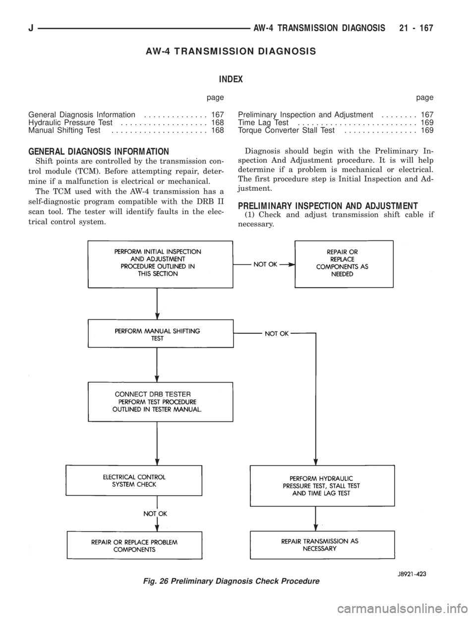
trical control system.Diagnosis should begin with the Preliminary In-
spection And Adjustment procedure. It is will help
determine if a problem is mechanical or electrical.
The first procedure step is Initial Inspection and Ad-
justment.
PRELIMINARY INSPECTION AND ADJUSTMENT
(1) Check and adjust transmission shift cable if
necessary.
Fig. 26 Preliminary Diagnosis Check Procedure
JAW-4 TRANSMISSION DIAGNOSIS 21 - 167
Page 1284 of 1784
AW-4 IN-VEHICLE SERVICE
INDEX
page page
Accumulator Pistons and Springs........... 179
Adapter Housing Seal Replacement.......... 182
Checking Fluid Level and Condition.......... 173
Manual Valve Shaft Seal Replacement....... 178
Park Interlock Cable Adjustment............ 186
Park Rod and Pawl Service................ 181
Park/Neutral Position Switch............... 173
Second Coast Brake Servo................ 181
Shift Cable Adjustment................... 186
Speed Sensor.......................... 182Speed Sensor RotorÐSpeedometer Drive Gear . 183
Throttle Position Sensor (TPS) Service....... 184
Transmission Control Module (TCM) Service . . . 173
Transmission Cooler Line Fittings........... 187
Transmission Cooler Service............... 187
Transmission Throttle Cable Adjustment....... 185
Transmission Throttle Cable Replacement..... 184
Transmission Valve Body Installation......... 177
Transmission Valve Body Removal.......... 176
Transmission Valve Body Solenoids.......... 175
CHECKING FLUID LEVEL AND CONDITION
Recommended fluid for AW-4 transmissions is Mo-
par Dexron IIE/Mercon. Mopar Dexron II may be
used if Mercon fluid is not readily available.
CHECKING FLUID LEVEL
(1) Be sure transmission fluid is at normal operat-
ing temperature. Normal operating temperature is
reached after approximately 15 miles (25 km) of op-
eration.
(2) Position vehicle on level surface. This is impor-
tant for an accurate fluid level check.
(3) Shift transmission through all gear ranges and
back to Park.
(4) Apply parking brakes.
(5) Verify that transmission is in Park.
(6) Wipe off dipstick handle to prevent dirt from
entering fill tube. Then remove dipstick and check
fluid level and condition.
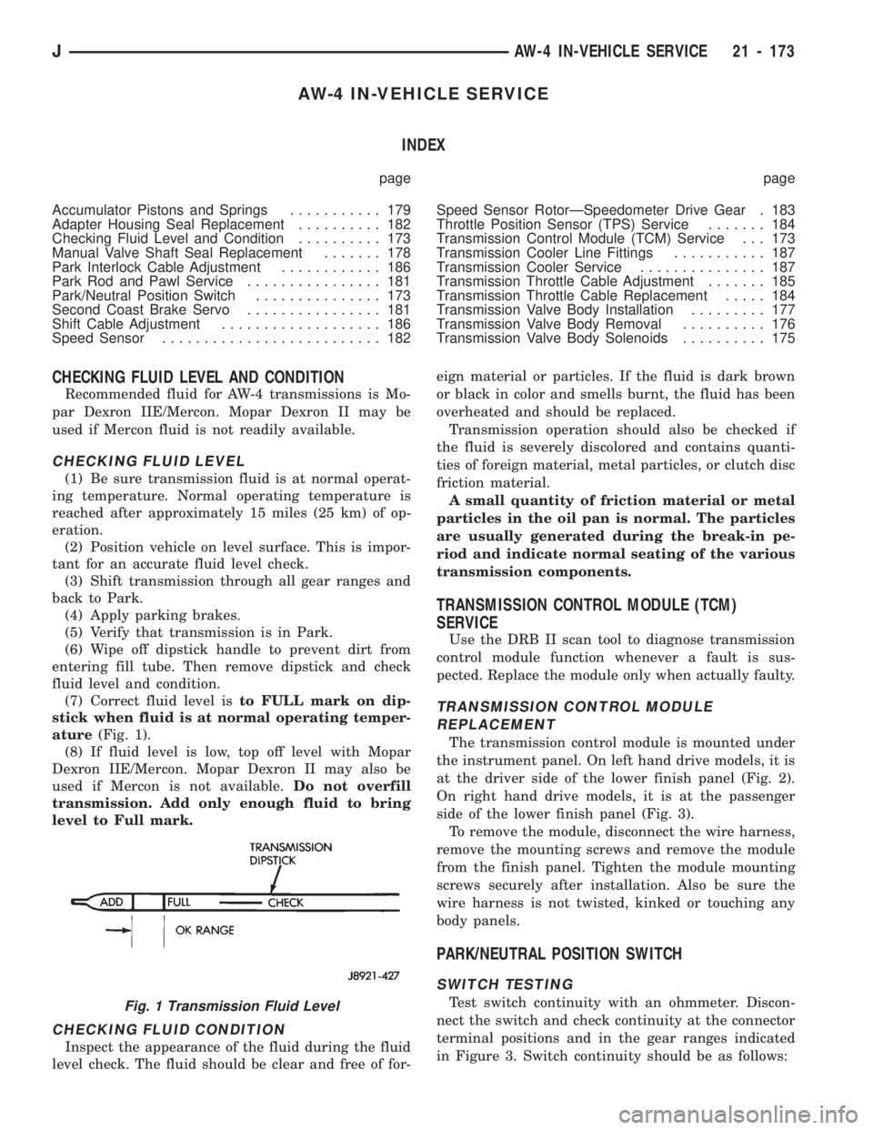
(7) Correct fluid level isto FULL mark on dip-
stick when fluid is at normal operating temper-
ature(Fig. 1).
(8) If fluid level is low, top off level with Mopar
Dexron IIE/Mercon. Mopar Dexron II may also be
used if Mercon is not available.Do not overfill
transmission. Add only enough fluid to bring
level to Full mark.
CHECKING FLUID CONDITION
Inspect the appearance of the fluid during the fluid
level check. The fluid should be clear and free of for-eign material or particles. If the fluid is dark brown
or black in color and smells burnt, the fluid has been
overheated and should be replaced.
Transmission operation should also be checked if
the fluid is severely discolored and contains quanti-
ties of foreign material, metal particles, or clutch disc
friction material.
A small quantity of friction material or metal
particles in the oil pan is normal. The particles
are usually generated during the break-in pe-
riod and indicate normal seating of the various
transmission components.
TRANSMISSION CONTROL MODULE (TCM)
SERVICE
Use the DRB II scan tool to diagnose transmission
control module function whenever a fault is sus-
pected. Replace the module only when actually faulty.
TRANSMISSION CONTROL MODULE
REPLACEMENT
The transmission control module is mounted under
the instrument panel. On left hand drive models, it is
at the driver side of the lower finish panel (Fig. 2).
On right hand drive models, it is at the passenger
side of the lower finish panel (Fig. 3).
To remove the module, disconnect the wire harness,
remove the mounting screws and remove the module
from the finish panel. Tighten the module mounting
screws securely after installation. Also be sure the
wire harness is not twisted, kinked or touching any
body panels.
PARK/NEUTRAL POSITION SWITCH
SWITCH TESTING
Test switch continuity with an ohmmeter. Discon-
nect the switch and check continuity at the connector
terminal positions and in the gear ranges indicated
in Figure 3. Switch continuity should be as follows:Fig. 1 Transmission Fluid Level
JAW-4 IN-VEHICLE SERVICE 21 - 173