1994 JEEP CHEROKEE index
[x] Cancel search: indexPage 1300 of 1784
AW-4 TRANSMISSION REMOVAL AND INSTALLATION
INDEX
page page
Oil Pump Seal Replacement............... 189
Torque Converter Stator Clutch Inspection..... 189Transmission and Torque Converter Installation . 190
Transmission and Torque Converter Removal . . 189
TRANSMISSION AND TORQUE CONVERTER
REMOVAL
(1) Raise vehicle.
(2) Drain transmission fluid and reinstall oil pan
drain plug.
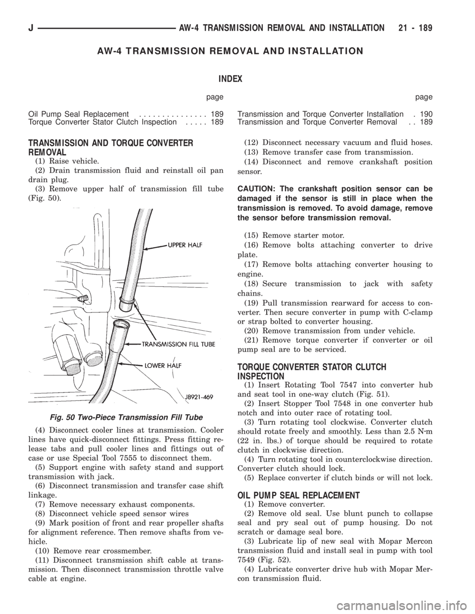
(3) Remove upper half of transmission fill tube
(Fig. 50).
(4) Disconnect cooler lines at transmission. Cooler
lines have quick-disconnect fittings. Press fitting re-
lease tabs and pull cooler lines and fittings out of
case or use Special Tool 7555 to disconnect them.
(5) Support engine with safety stand and support
transmission with jack.
(6) Disconnect transmission and transfer case shift
linkage.
(7) Remove necessary exhaust components.
(8) Disconnect vehicle speed sensor wires
(9) Mark position of front and rear propeller shafts
for alignment reference. Then remove shafts from ve-
hicle.
(10) Remove rear crossmember.
(11) Disconnect transmission shift cable at trans-
mission. Then disconnect transmission throttle valve
cable at engine.(12) Disconnect necessary vacuum and fluid hoses.
(13) Remove transfer case from transmission.
(14) Disconnect and remove crankshaft position
sensor.
CAUTION: The crankshaft position sensor can be
damaged if the sensor is still in place when the
transmission is removed. To avoid damage, remove
the sensor before transmission removal.
(15) Remove starter motor.
(16) Remove bolts attaching converter to drive
plate.
(17) Remove bolts attaching converter housing to
engine.
(18) Secure transmission to jack with safety
chains.
(19) Pull transmission rearward for access to con-
verter. Then secure converter in pump with C-clamp
or strap bolted to converter housing.
(20) Remove transmission from under vehicle.
(21) Remove torque converter if converter or oil
pump seal are to be serviced.
TORQUE CONVERTER STATOR CLUTCH
INSPECTION
(1) Insert Rotating Tool 7547 into converter hub
and seat tool in one-way clutch (Fig. 51).
(2) Insert Stopper Tool 7548 in one converter hub
notch and into outer race of rotating tool.
(3) Turn rotating tool clockwise. Converter clutch
should rotate freely and smoothly. Less than 2.5 Nzm
(22 in. lbs.) of torque should be required to rotate
clutch in clockwise direction.
(4) Turn rotating tool in counterclockwise direction.
Converter clutch should lock.
(5)
Replace converter if clutch binds or will not lock.
OIL PUMP SEAL REPLACEMENT
(1) Remove converter.
(2) Remove old seal. Use blunt punch to collapse
seal and pry seal out of pump housing. Do not
scratch or damage seal bore.
(3) Lubricate lip of new seal with Mopar Mercon
transmission fluid and install seal in pump with tool
7549 (Fig. 52).
(4) Lubricate converter drive hub with Mopar Mer-
con transmission fluid.
Fig. 50 Two-Piece Transmission Fill Tube
JAW-4 TRANSMISSION REMOVAL AND INSTALLATION 21 - 189
Page 1303 of 1784
AW-4 TRANSMISSION OVERHAUL
INDEX
page page
Cleaning and Inspection................... 76
Direct Clutch Overhaul................... 219
First-Reverse Brake Piston and Transmission
Case Overhaul........................ 237
Forward Clutch Overhaul.................. 223
Front Planetary Gear Overhaul............. 228
Manual Valve Shaft Overhaul.............. 205
Oil Pump Overhaul...................... 206
Overdrive Planetary Gear and Clutch Overhaul . 209Overdrive Support Overhaul................ 216
Overhaul Service Tools................... 192
Rear Planetary, No. 2 One-Way Clutch and
Output Shaft Overhaul.................. 100
Second Brake Overhaul................... 100
Sun Gear and No. 1 One-Way Clutch Overhaul . 99
Transmission Assembly and Adjustment....... 255
Transmission Disassembly................. 192
Transmission Valve Body Overhaul.......... 101
OVERHAUL SERVICE TOOLS
The special tools needed to overhaul the AW-4
transmission are provided in Tool Kit 6294. However,
Pressure Test Port Adapter 7554 is not included in
this kit and must be ordered separately. The over-
haul tool kit and test port adapter are available
through the parts division and dealer special tool
program.
TRANSMISSION DISASSEMBLY
(1) Remove torque converter.
(2) Remove lower half of filler tube if not previ-
ously removed.
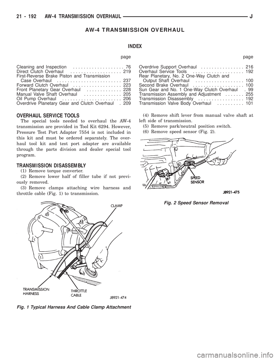
(3) Remove clamps attaching wire harness and
throttle cable (Fig. 1) to transmission.(4) Remove shift lever from manual valve shaft at
left side of transmission.
(5) Remove park/neutral position switch.
(6) Remove speed sensor (Fig. 2).
Fig. 1 Typical Harness And Cable Clamp Attachment
Fig. 2 Speed Sensor Removal
21 - 192 AW-4 TRANSMISSION OVERHAULJ
Page 1383 of 1784
NP231 TRANSFER CASE
INDEX
page page
General Information...................... 272
Shift Linkage Adjustment.................. 275
Speedometer Service.................... 275
Transfer Case Assembly.................. 282
Transfer Case Disassembly and Overhaul..... 277Transfer Case Identification................ 273
Transfer Case Installation................. 276
Transfer Case Lubricant.................. 273
Transfer Case Removal................... 276
GENERAL INFORMATION
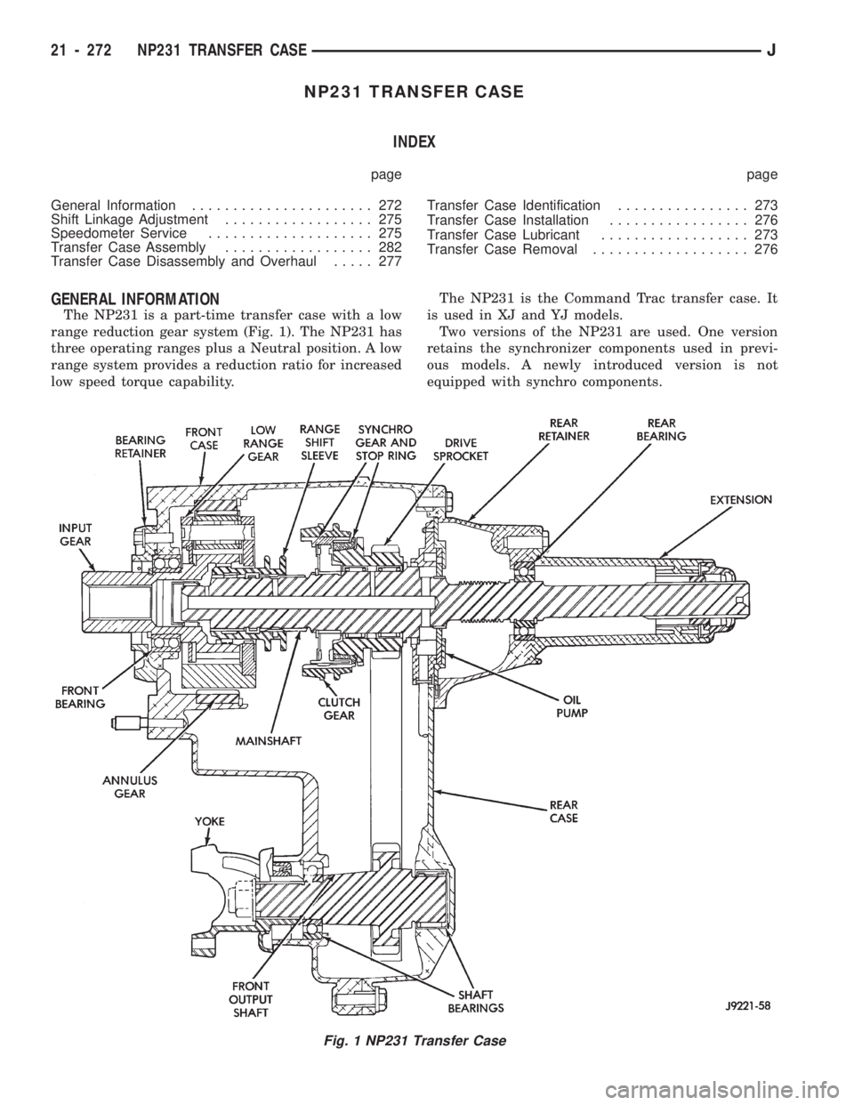
The NP231 is a part-time transfer case with a low
range reduction gear system (Fig. 1). The NP231 has
three operating ranges plus a Neutral position. A low
range system provides a reduction ratio for increased
low speed torque capability.The NP231 is the Command Trac transfer case. It
is used in XJ and YJ models.
Two versions of the NP231 are used. One version
retains the synchronizer components used in previ-
ous models. A newly introduced version is not
equipped with synchro components.
Fig. 1 NP231 Transfer Case
21 - 272 NP231 TRANSFER CASEJ
Page 1404 of 1784
NP242 TRANSFER CASE
INDEX
page page
Cleaning and Inspection.................. 305
General Information...................... 293
Shift Linkage Adjustment.................. 296
Speedometer Service.................... 296
Transfer Case Assembly.................. 306
Transfer Case Disassembly and Overhaul..... 297Transfer Case Fill Level.................. 294
Transfer Case Identification................ 293
Transfer Case Installation................. 296
Transfer Case Lubricant.................. 294
Transfer Case Removal................... 296
GENERAL INFORMATION
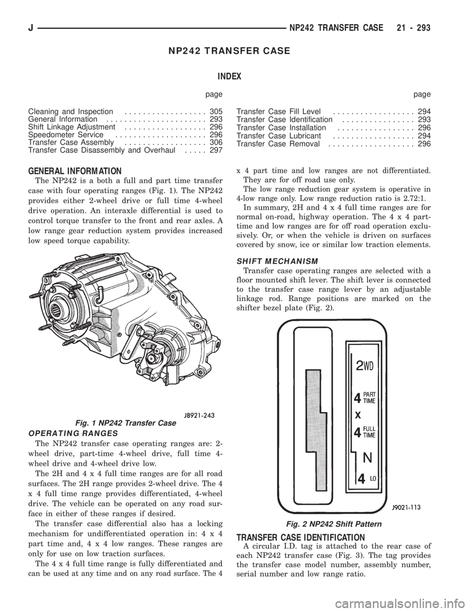
The NP242 is a both a full and part time transfer
case with four operating ranges (Fig. 1). The NP242
provides either 2-wheel drive or full time 4-wheel
drive operation. An interaxle differential is used to
control torque transfer to the front and rear axles. A
low range gear reduction system provides increased
low speed torque capability.
OPERATING RANGES
The NP242 transfer case operating ranges are: 2-
wheel drive, part-time 4-wheel drive, full time 4-
wheel drive and 4-wheel drive low.
The2Hand4x4full time ranges are for all road
surfaces. The 2H range provides 2-wheel drive. The 4
x 4 full time range provides differentiated, 4-wheel
drive. The vehicle can be operated on any road sur-
face in either of these ranges if desired.
The transfer case differential also has a locking
mechanism for undifferentiated operation in:4x4
part time and,4x4lowranges. These ranges are
only for use on low traction surfaces.
The4x4full time range is fully differentiated and
can be used at any time and on any road surface. The 4x 4 part time and low ranges are not differentiated.
They are for off road use only.
The low range reduction gear system is operative in
4-low range only. Low range reduction ratio is 2.72:1.
In summary, 2H and4x4full time ranges are for
normal on-road, highway operation. The4x4part-
time and low ranges are for off road operation exclu-
sively. Or, or when the vehicle is driven on surfaces
covered by snow, ice or similar low traction elements.
SHIFT MECHANISM
Transfer case operating ranges are selected with a
floor mounted shift lever. The shift lever is connected
to the transfer case range lever by an adjustable
linkage rod. Range positions are marked on the
shifter bezel plate (Fig. 2).
TRANSFER CASE IDENTIFICATION
A circular I.D. tag is attached to the rear case of
each NP242 transfer case (Fig. 3). The tag provides
the transfer case model number, assembly number,
serial number and low range ratio.
Fig. 1 NP242 Transfer Case
Fig. 2 NP242 Shift Pattern
JNP242 TRANSFER CASE 21 - 293
Page 1444 of 1784
WHEELS AND TIRES
CONTENTS
page page
SPECIFICATIONS....................... 11
TIRES................................. 1VEHICLE VIBRATION..................... 9
WHEELS............................... 6
TIRES
INDEX
page page
Cleaning of Tires.......................... 2
General Information........................ 1
Pressure Gauges......................... 2
Repairing Leaks.......................... 3
Replacement Tires........................ 2Rotation................................ 3
Tire Inflation Pressures..................... 2
Tire Noise or Vibration..................... 4
Tire Wear Patterns........................ 4
Tread Wear Indicators...................... 3
GENERAL INFORMATION
Tires are designed for each specific vehicle. They
provide the best overall performance for normal op-
eration. The ride and handling characteristics match
the vehicle's requirements. With proper care they
will give excellent reliability, traction, skid resis-
tance, and tread life. These tires have specific load
carrying capacities. When correctly inflated, they
will operate properly.
Tires used in cool climates, and with light loads
will have a longer life than tires used in hot climates
with heavy loads. Abrasive road surfaces will accel-
erate tire wear.
Driving habits have more effect on tire life than
any other factor. Careful drivers will obtain much
greater mileage than careless drivers.
Driving habits that shorten the life of any tire;
²Rapid acceleration and deceleration
²Severe application of brakes
²High-speed driving
²Taking turns at excessive speeds
²Striking curbs and other obstacles
It is very important to follow the tire rotation in-
terval
IDENTIFICATION
Tire type, size, aspect ratio and speed rating are
encoded in the letters and numbers imprinted on the
side wall of the tire. Refer to the chart to decipher
the tire identification code (Fig. 1).
Performance tires will have a speed rating letter
after the aspect ratio number. The speed rating isnot always printed on the tire sidewall. The letterS
indicates that the tire is speed rated up to 112 mph.
²Qup to 100 mph
²Tup to 118 mph
²Uup to 124 mph
²Hup to 130 mph
²Vup to 149 mph
²Zmore than 149 mph (consult the tire manufac-
turer for the specific speed rating)
An All Season type tire will have eitherM+S,M
&SorMÐS(indicating mud and snow traction) im-
printed on the side wall.
RADIAL-PLY TIRES
Radial-ply tires improve handling, tread life, ride
quality and decrease rolling resistance.
Radial-ply tires must always be used in sets of
four. Under no circumstances should they be used on
the front only. They may be mixed with temporary
spare tires when necessary, but reduced speeds are
recommended.
Radial-ply tires have the same load-carrying capac-
ity as other types of tires of the same size. They use
the same recommended inflation pressures.
SPARE TIRE (TEMPORARY)
The compact spare tire is designed for emergency
use only. The original tire should be repaired and re-
installed at the first opportunity. Refer to Owner's
Manual for complete details.
JWHEELS AND TIRES 22 - 1
Page 1483 of 1784
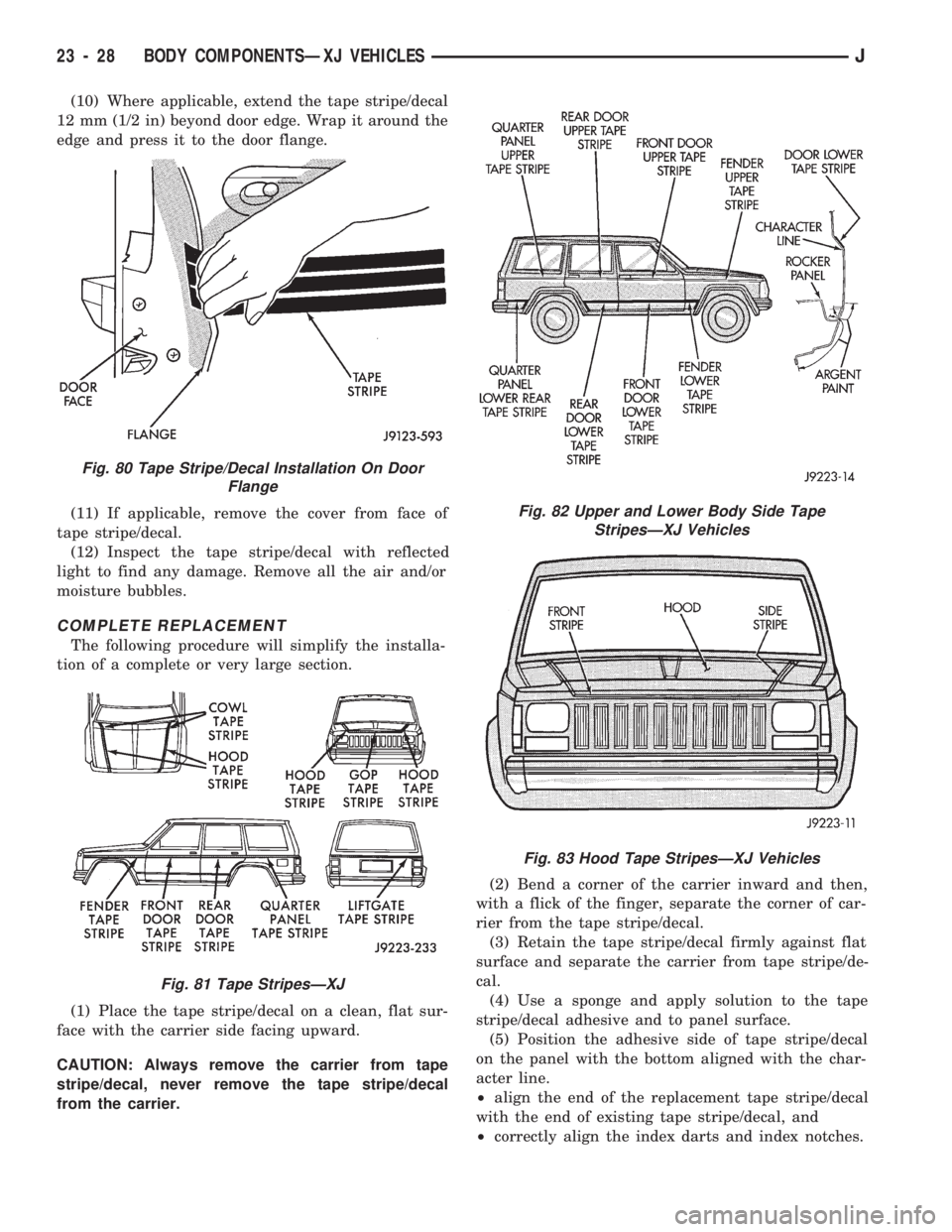
(10) Where applicable, extend the tape stripe/decal
12 mm (1/2 in) beyond door edge. Wrap it around the
edge and press it to the door flange.
(11) If applicable, remove the cover from face of
tape stripe/decal.
(12) Inspect the tape stripe/decal with reflected
light to find any damage. Remove all the air and/or
moisture bubbles.
COMPLETE REPLACEMENT
The following procedure will simplify the installa-
tion of a complete or very large section.
(1) Place the tape stripe/decal on a clean, flat sur-
face with the carrier side facing upward.
CAUTION: Always remove the carrier from tape
stripe/decal, never remove the tape stripe/decal
from the carrier.(2) Bend a corner of the carrier inward and then,
with a flick of the finger, separate the corner of car-
rier from the tape stripe/decal.
(3) Retain the tape stripe/decal firmly against flat
surface and separate the carrier from tape stripe/de-
cal.
(4) Use a sponge and apply solution to the tape
stripe/decal adhesive and to panel surface.
(5) Position the adhesive side of tape stripe/decal
on the panel with the bottom aligned with the char-
acter line.
²align the end of the replacement tape stripe/decal
with the end of existing tape stripe/decal, and
²correctly align the index darts and index notches.
Fig. 80 Tape Stripe/Decal Installation On Door
Flange
Fig. 81 Tape StripesÐXJ
Fig. 82 Upper and Lower Body Side Tape
StripesÐXJ Vehicles
Fig. 83 Hood Tape StripesÐXJ Vehicles
23 - 28 BODY COMPONENTSÐXJ VEHICLESJ
Page 1489 of 1784
DOORS
INDEX
page page
Door Alignment AdjustmentÐMajor........... 47
Door Alignment AdjustmentÐMinor........... 46
Door Edge Guard/Edge Protector Strip........ 61
Door External Handle..................... 55
Door Hinge/Hinge Pin Replacement........... 58
Door Inside Latch Release and Lock Rods..... 57
Door Key Lock Cylinder................... 54
Door Latch............................. 56
Door Latch Adjustment.................... 55
Door Removal/Installation.................. 40
Door Restraint Replacement................ 47
Door Trim Panel......................... 35
Door Window Exterior Mouldings............. 61
Door Window Glass and Door Opening
Weatherstrip Seals...................... 62
Front Door Spacer BlocksÐTwo-Door Vehicles . . 60
Front Door Vent Window................... 50
Front Door Window Glass.................. 49Front Door Window Glass Regulator.......... 48
Liftgate Adjustment....................... 70
Liftgate Hinge........................... 67
Liftgate Latch/Key Lock Cylinder/Striker........ 68
Liftgate License Plate Lamp Housing.......... 72
Liftgate License Plate Screw Anchor and Bumper . 72
Liftgate Opening Weatherstrip Seal........... 70
Liftgate Removal/Installation................ 65
Liftgate Service InformationÐXJ Vehicles...... 65
Liftgate Support Rod Ball Stud Replacement.... 70
Liftgate Support Rod Cylinder............... 69
Liftgate Support Rod Cylinder Disposal........ 70
Liftgate Trim Panel....................... 66
Rear Door Fixed Window Glass............. 53
Rear Door Window Glass.................. 52
Rear Door Window Glass Regulator.......... 51
Service Information....................... 34
SERVICE INFORMATION
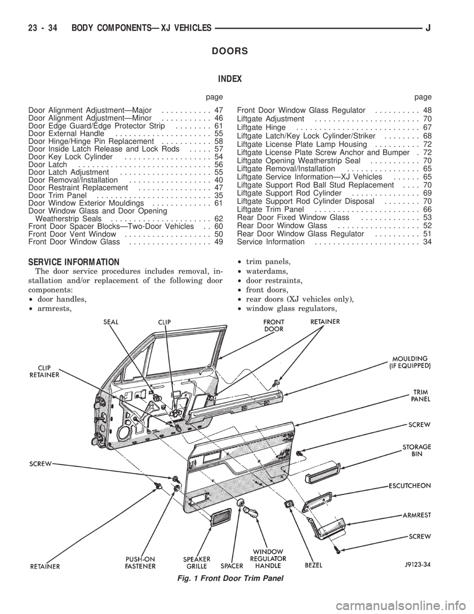
The door service procedures includes removal, in-
stallation and/or replacement of the following door
components:
²door handles,
²armrests,²trim panels,
²waterdams,
²door restraints,
²front doors,
²rear doors (XJ vehicles only),
²window glass regulators,
Fig. 1 Front Door Trim Panel
23 - 34 BODY COMPONENTSÐXJ VEHICLESJ
Page 1528 of 1784
FIXED WINDOW GLASS
INDEX
page page
Fixed Glass Water Leak Detection and Repair . . 83
Interior Rearview Mirror.................... 74
Interior Rearview Mirror Support Bracket
Replacement.......................... 75
Liftgate Window GlassÐXJ Vehicles.......... 81
Rear Quarter Vent Window GlassÐXJ Vehicles . 80Rear Quarter Window Glass/Rear Quarter
Plastic Insert ÐXJ Vehicles............... 80
Service Information....................... 73
Windshield Glass Replacement.............. 75
Windshield Reveal Moulding................ 73
Windshield Service Information.............. 75
SERVICE INFORMATION
The following service procedures include removal
and installation of the:
²windshield reveal moulding,
²interior rearview mirror,
²windshield glass (using both the short and the ex-
tended installation method),
²rear quarter vent window glass,
²rear quarter window glass,
²liftgate window glass,
²cab rear window, and
²leak detection and repair.
WINDSHIELD REVEAL MOULDING
REMOVAL
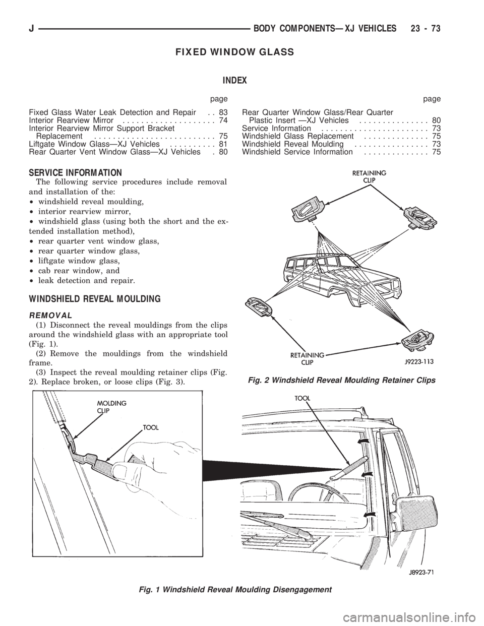
(1) Disconnect the reveal mouldings from the clips
around the windshield glass with an appropriate tool
(Fig. 1).
(2) Remove the mouldings from the windshield
frame.
(3) Inspect the reveal moulding retainer clips (Fig.
2). Replace broken, or loose clips (Fig. 3).
Fig. 1 Windshield Reveal Moulding Disengagement
Fig. 2 Windshield Reveal Moulding Retainer Clips
JBODY COMPONENTSÐXJ VEHICLES 23 - 73