1994 JEEP CHEROKEE index
[x] Cancel search: indexPage 1026 of 1784
SERVICE DIAGNOSIS/PROCEDURES
INDEX
page page
Runout................................. 4
Unbalance............................... 3Universal Joint Angle Measurement............ 4
Vibration................................ 3
VIBRATION
Tires that are out-of-round or wheels that are un-
balanced will cause a low frequency vibration. Refer
to Group 22, Wheels and Tires for additional infor-
mation.
Brake drums that are unbalanced will cause a
harsh, low frequency vibration. Refer to Group 5,
Brakes for additional information.
Driveline vibration can also result from loose or
damaged engine mounts. Refer to Group 21, Trans-
missions for additional information.
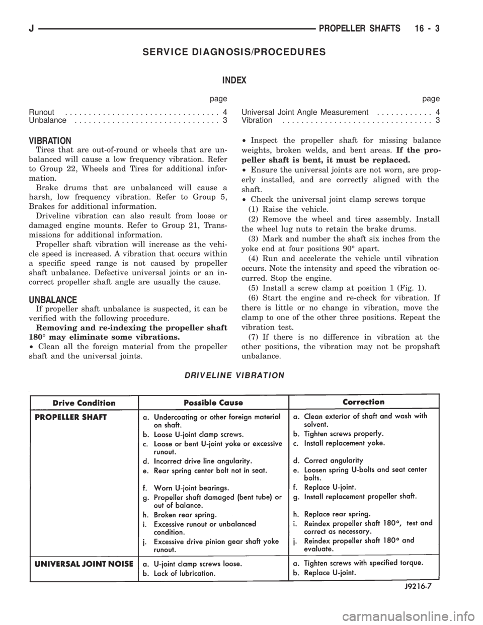
Propeller shaft vibration will increase as the vehi-
cle speed is increased. A vibration that occurs within
a specific speed range is not caused by propeller
shaft unbalance. Defective universal joints or an in-
correct propeller shaft angle are usually the cause.
UNBALANCE
If propeller shaft unbalance is suspected, it can be
verified with the following procedure.
Removing and re-indexing the propeller shaft
180É may eliminate some vibrations.
²Clean all the foreign material from the propeller
shaft and the universal joints.²Inspect the propeller shaft for missing balance
weights, broken welds, and bent areas.If the pro-
peller shaft is bent, it must be replaced.
²Ensure the universal joints are not worn, are prop-
erly installed, and are correctly aligned with the
shaft.
²Check the universal joint clamp screws torque
(1) Raise the vehicle.
(2) Remove the wheel and tires assembly. Install
the wheel lug nuts to retain the brake drums.
(3) Mark and number the shaft six inches from the
yoke end at four positions 90É apart.
(4) Run and accelerate the vehicle until vibration
occurs. Note the intensity and speed the vibration oc-
curred. Stop the engine.
(5) Install a screw clamp at position 1 (Fig. 1).
(6) Start the engine and re-check for vibration. If
there is little or no change in vibration, move the
clamp to one of the other three positions. Repeat the
vibration test.
(7) If there is no difference in vibration at the
other positions, the vibration may not be propshaft
unbalance.
DRIVELINE VIBRATION
JPROPELLER SHAFTS 16 - 3
Page 1046 of 1784
POWER STEERING PUMP
INDEX
page page
Drive Pulley Replacement.................. 11
Flow Control Valve Fitting O-Ring Seal........ 12
Power Steering PumpÐInitial Operation....... 13
Pressure and Return Hose Replacement........ 9Pump Replacement....................... 10
Reservoir Replacement.................... 12
Service Information........................ 9
SERVICE INFORMATION
The power steering pump internal components are
not serviced or adjusted. If a malfunction or an inter-
nal fluid leak occurs, the complete unit must be re-
placed. A reservoir, cap, and O-ring seal kit are the
only service components available.
PRESSURE AND RETURN HOSE REPLACEMENT
Cap hose open ends and pump/steering gear fit-
tings to prevent entry of foreign material.
WARNING: POWER STEERING FLUID (AND PUMP
COMPONENTS) AND THE EXHAUST SYSTEM CAN
BE EXTREMELY HOT IF THE ENGINE HAS BEEN
RECENTLY OPERATING. DO NOT START THE EN-
GINE WITH ANY LOOSE OR DISCONNECTED
HOSES. DO NOT ALLOW THE HOSES TO TOUCH A
HOT EXHAUST MANIFOLD OR THE CATALYTIC
CONVERTER.
REMOVAL
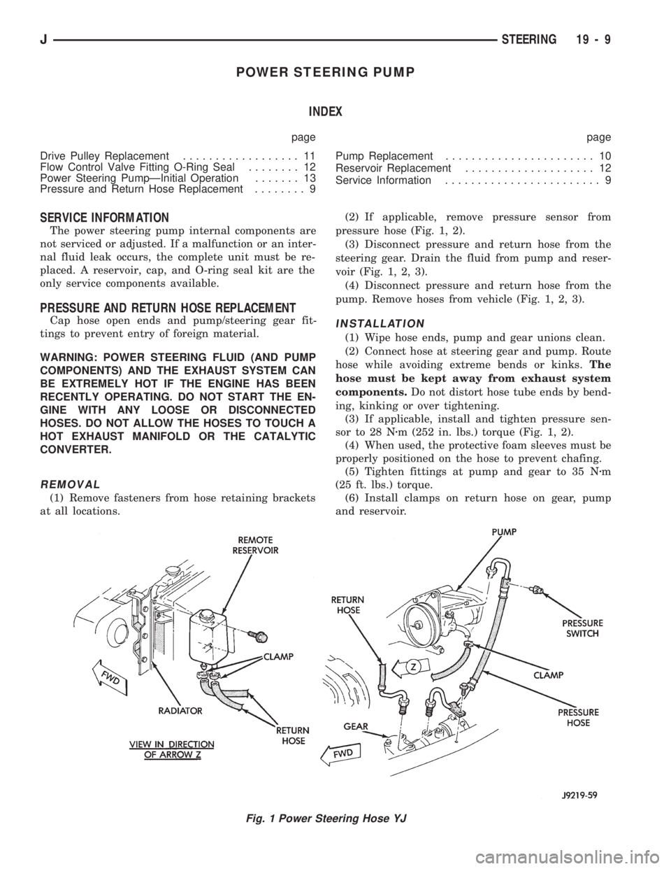
(1) Remove fasteners from hose retaining brackets
at all locations.(2) If applicable, remove pressure sensor from
pressure hose (Fig. 1, 2).
(3) Disconnect pressure and return hose from the
steering gear. Drain the fluid from pump and reser-
voir (Fig. 1, 2, 3).
(4) Disconnect pressure and return hose from the
pump. Remove hoses from vehicle (Fig. 1, 2, 3).
INSTALLATION
(1) Wipe hose ends, pump and gear unions clean.
(2) Connect hose at steering gear and pump. Route
hose while avoiding extreme bends or kinks.The
hose must be kept away from exhaust system
components.Do not distort hose tube ends by bend-
ing, kinking or over tightening.
(3) If applicable, install and tighten pressure sen-
sor to 28 Nzm (252 in. lbs.) torque (Fig. 1, 2).
(4) When used, the protective foam sleeves must be
properly positioned on the hose to prevent chafing.
(5) Tighten fittings at pump and gear to 35 Nzm
(25 ft. lbs.) torque.
(6) Install clamps on return hose on gear, pump
and reservoir.
Fig. 1 Power Steering Hose YJ
JSTEERING 19 - 9
Page 1051 of 1784
STEERING LINKAGEÐXJ
INDEX
page page
Drag Link.............................. 14
Pitman Arm............................. 15
Service Information....................... 14Steering Dampener....................... 15
Tie Rod ................................ 14
SERVICE INFORMATION
The steering linkage consists of a pitman arm, drag
link, tie rod, and steering dampener. Adjustment
sleeves are used on the tie rod and drag link for toe
and steering wheel alignment.
Refer to Group 2, Front Suspension and Axle for
additional information.
The tie-rod end ball stud seals should be inspected
during all oil changes.
A damaged ball stud seal requires removal of the
seal. Inspect the tie-rod end ball stud at the throat
opening. Check for lubricant loss, contamination, ball
stud wear or corrosion. If these conditions exist, re-
place the tie-rod. A replacement seal can be installed
if lubricant is in good condition. Otherwise, a com-
plete replacement ball stud end should be installed.
Lubricate the tie-rod end with MOPARtMulti-Mile-
age Lubricant, or equivalent product.
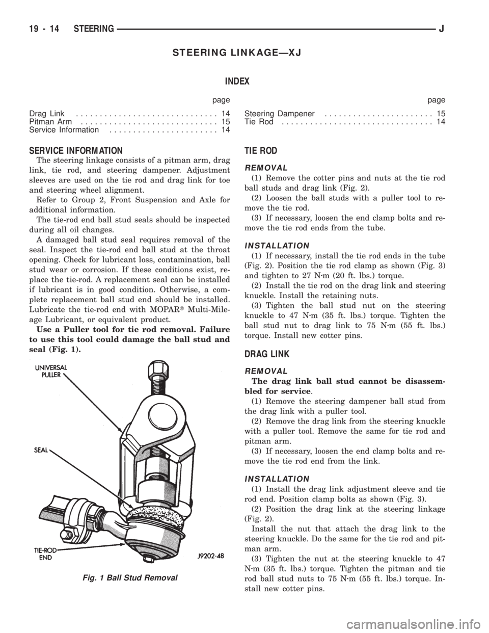
Use a Puller tool for tie rod removal. Failure
to use this tool could damage the ball stud and
seal (Fig. 1).
TIE ROD
REMOVAL
(1) Remove the cotter pins and nuts at the tie rod
ball studs and drag link (Fig. 2).
(2) Loosen the ball studs with a puller tool to re-
move the tie rod.
(3) If necessary, loosen the end clamp bolts and re-
move the tie rod ends from the tube.
INSTALLATION
(1) If necessary, install the tie rod ends in the tube
(Fig. 2). Position the tie rod clamp as shown (Fig. 3)
and tighten to 27 Nzm (20 ft. lbs.) torque.
(2) Install the tie rod on the drag link and steering
knuckle. Install the retaining nuts.
(3) Tighten the ball stud nut on the steering
knuckle to 47 Nzm (35 ft. lbs.) torque. Tighten the
ball stud nut to drag link to 75 Nzm (55 ft. lbs.)
torque. Install new cotter pins.
DRAG LINK
REMOVAL
The drag link ball stud cannot be disassem-
bled for service.
(1) Remove the steering dampener ball stud from
the drag link with a puller tool.
(2) Remove the drag link from the steering knuckle
with a puller tool. Remove the same for tie rod and
pitman arm.
(3) If necessary, loosen the end clamp bolts and re-
move the tie rod end from the link.
INSTALLATION
(1) Install the drag link adjustment sleeve and tie
rod end. Position clamp bolts as shown (Fig. 3).
(2) Position the drag link at the steering linkage
(Fig. 2).
Install the nut that attach the drag link to the
steering knuckle. Do the same for the tie rod and pit-
man arm.
(3) Tighten the nut at the steering knuckle to 47
Nzm (35 ft. lbs.) torque. Tighten the pitman and tie
rod ball stud nuts to 75 Nzm (55 ft. lbs.) torque. In-
stall new cotter pins.
Fig. 1 Ball Stud Removal
19 - 14 STEERINGJ
Page 1054 of 1784
STEERING LINKAGEÐYJ
INDEX
page page
Drag Link.............................. 17
Pitman Arm............................. 18
Service Information....................... 17Steering Dampener....................... 18
Tie Rod ................................ 17
SERVICE INFORMATION
The steering linkage consists of a pitman arm, drag
link, tie rod, and steering dampener. Adjustment
sleeves are used on the tie rod and drag link for toe
and steering wheel alignment.
Refer to Group 2, Front Suspension and Axle for
additional information.
The tie-rod end ball stud seals should be inspected
during all oil changes.
A damaged ball stud seal requires removal of the
seal. Inspect the tie-rod end ball stud at the throat
opening. Check for lubricant loss, contamination, ball
stud wear or corrosion. If these conditions exist, re-
place the tie-rod. A replacement seal can be installed
if lubricant is in good condition. Otherwise, a com-
plete replacement ball stud end should be installed.
Lubricate the tie-rod end with MOPARtMulti-Mile-
age Lubricant, or equivalent product.
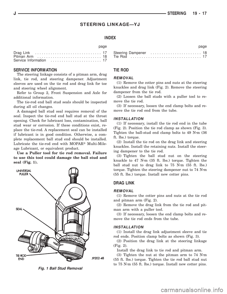
Use a Puller tool for tie rod removal. Failure
to use this tool could damage the ball stud and
seal (Fig. 1).
TIE ROD
REMOVAL
(1) Remove the cotter pins and nuts at the steering
knuckles and drag link (Fig. 2). Remove the steering
dampener from the tie rod.
(2) Loosen the ball studs with a puller tool to re-
move the tie rod.
(3) If necessary, loosen the end clamp bolts and re-
move the tie rod end from the tube.
INSTALLATION
(1) If necessary, install the tie rod end in the tube
(Fig. 2). Position the tie rod clamp as shown (Fig. 3).
Tighten the ball-stud end clamp bolts to 49 Nzm (36
ft. lbs.) torque.
(2) Install the tie rod on the drag link and steering
knuckles. Install the retaining nuts. Install the steer-
ing dampener to the tie rod.
(3) Tighten the ball stud nut on the steering
knuckle to 47 Nzm (35 ft. lbs.) torque. Tighten the
ball stud nut to drag link to 75 Nzm (55 ft. lbs.)
torque. Tighten the steering dampener nut to 74 Nzm
(55 ft. lbs.) torque. Install new cotter pins.
DRAG LINK
REMOVAL
(1) Remove the cotter pins and nuts at the tie rod
and pitman arm (Fig. 2).
(2) Remove the drag link from the tie rod and pit-
man arm with a puller tool.
(3) If necessary, loosen the end clamp bolts and re-
move the tie rod ends from the tube.
INSTALLATION
(1) Install the drag link adjustment sleeve and tie
rod ends. Position clamp bolts as shown (Fig. 3).
(2) Position the drag link at the steering linkage
(Fig. 2).
Install the drag link to tie rod and pitman arm.
(3) Tighten the nut at the pitman arm to 74 Nzm
(55 ft. lbs.) torque. Tighten the tie rod ball stud nut
to 75 Nzm (55 ft. lbs.) torque. Install new cotter pins.
Fig. 1 Ball Stud Removal
JSTEERING 19 - 17
Page 1056 of 1784
INSTALLATION
(1) Align and install the pitman arm on steering
gear shaft.
(2) Install the washer and nut on the shaft.
Tighten the nut to 251 Nzm (185 ft. lbs.) torque.
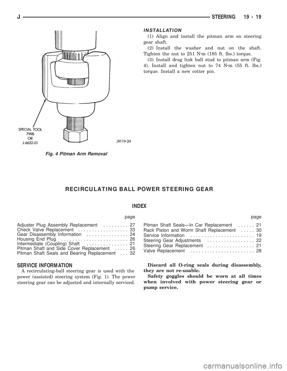
(3) Install drag link ball stud to pitman arm (Fig.
4). Install and tighten nut to 74 Nzm (55 ft. lbs.)
torque. Install a new cotter pin.
RECIRCULATING BALL POWER STEERING GEAR
INDEX
page page
Adjuster Plug Assembly Replacement......... 27
Check Valve Replacement.................. 33
Gear Disassembly Information............... 24
Housing End Plug........................ 26
Intermediate (Coupling) Shaft............... 21
Pitman Shaft and Side Cover Replacement..... 26
Pitman Shaft Seals and Bearing Replacement . . . 32Pitman Shaft SealsÐIn Car Replacement...... 21
Rack Piston and Worm Shaft Replacement..... 30
Service Information....................... 19
Steering Gear Adjustments................. 22
Steering Gear Replacement................. 21
Valve Replacement....................... 28
SERVICE INFORMATION
A recirculating-ball steering gear is used with the
power (assisted) steering system (Fig. 1). The power
steering gear can be adjusted and internally serviced.Discard all O-ring seals during disassembly,
they are not re-usable.
Safety goggles should be worn at all times
when involved with power steering gear or
pump service.
Fig. 4 Pitman Arm Removal
JSTEERING 19 - 19
Page 1060 of 1784
²SECOND - over-center preload adjustment
WORM THRUST BEARING PRELOAD
ADJUSTMENT
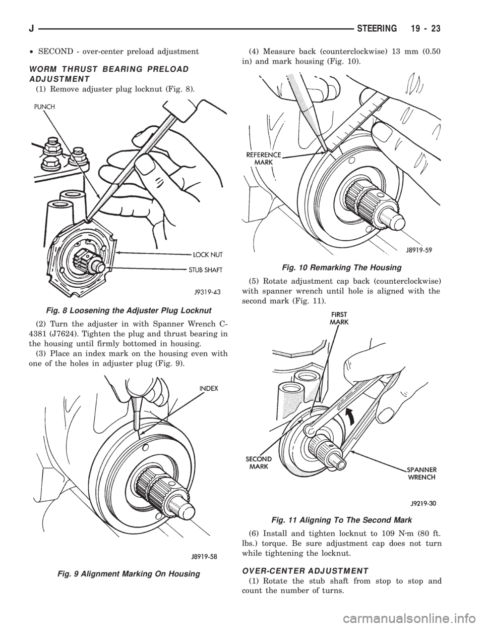
(1) Remove adjuster plug locknut (Fig. 8).
(2) Turn the adjuster in with Spanner Wrench C-
4381 (J7624). Tighten the plug and thrust bearing in
the housing until firmly bottomed in housing.
(3) Place an index mark on the housing even with
one of the holes in adjuster plug (Fig. 9).(4) Measure back (counterclockwise) 13 mm (0.50
in) and mark housing (Fig. 10).
(5) Rotate adjustment cap back (counterclockwise)
with spanner wrench until hole is aligned with the
second mark (Fig. 11).
(6) Install and tighten locknut to 109 Nzm (80 ft.
lbs.) torque. Be sure adjustment cap does not turn
while tightening the locknut.
OVER-CENTER ADJUSTMENT
(1) Rotate the stub shaft from stop to stop and
count the number of turns.
Fig. 10 Remarking The Housing
Fig. 11 Aligning To The Second Mark
Fig. 8 Loosening the Adjuster Plug Locknut
Fig. 9 Alignment Marking On Housing
JSTEERING 19 - 23
Page 1072 of 1784
MANUAL STEERING GEAR
INDEX
page page
Diagnosis.............................. 35
Gear Adjustments in Vehicle................ 37
Gear Adjustments on Bench................ 42
Gear Assembly.......................... 41
Gear Cleaning and Inspection............... 40Gear Disassembly........................ 37
Information............................. 35
Intermediate (Coupler) Shaft................ 43
Pitman Shaft Seal Replacement............. 35
Steering Gear Replacement................. 43
INFORMATION
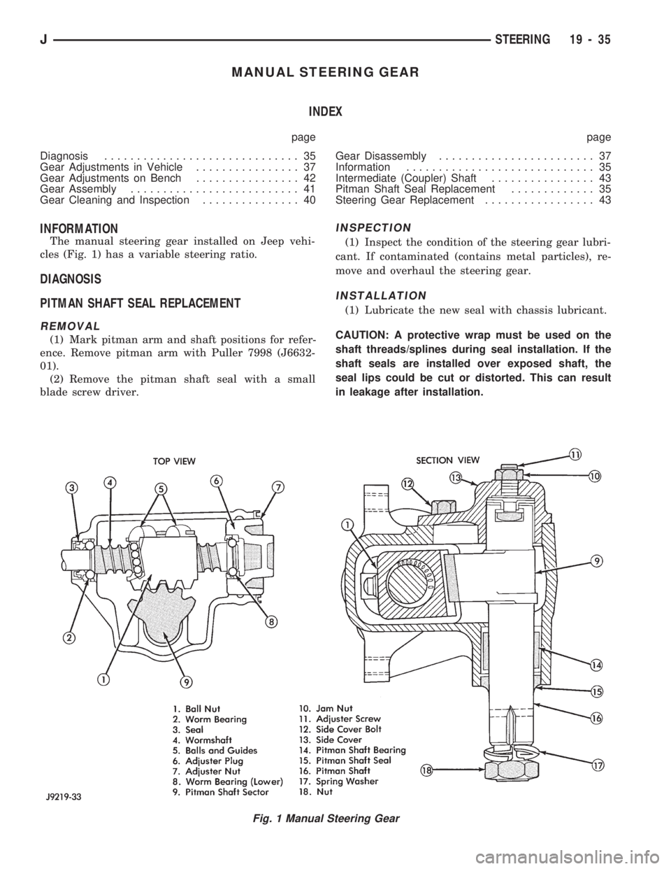
The manual steering gear installed on Jeep vehi-
cles (Fig. 1) has a variable steering ratio.
DIAGNOSIS
PITMAN SHAFT SEAL REPLACEMENT
REMOVAL
(1) Mark pitman arm and shaft positions for refer-
ence. Remove pitman arm with Puller 7998 (J6632-
01).
(2) Remove the pitman shaft seal with a small
blade screw driver.
INSPECTION
(1) Inspect the condition of the steering gear lubri-
cant. If contaminated (contains metal particles), re-
move and overhaul the steering gear.
INSTALLATION
(1) Lubricate the new seal with chassis lubricant.
CAUTION: A protective wrap must be used on the
shaft threads/splines during seal installation. If the
shaft seals are installed over exposed shaft, the
seal lips could be cut or distorted. This can result
in leakage after installation.
Fig. 1 Manual Steering Gear
JSTEERING 19 - 35
Page 1082 of 1784
STEERING COLUMN GENERAL SERVICE
INDEX
page page
Column ReplacementÐXJ.................. 46
Column ReplacementÐYJ.................. 48
Park-Lock CableÐConsole Shift Automatic..... 45Service Information....................... 45
Steering Wheel.......................... 45
SERVICE INFORMATION
The column may be disassembled and reassembled.
Also most steering column components can be ser-
viced without removing the column from the vehicle.
For additional information, refer to Group 8H, Elec-
trical.
CAUTION: Bumping, jolting and hammering on the
steering column shaft and gear shift tube must be
avoided during all service procedures.
CAUTION: Disconnect negative (ground) cable from
the battery before servicing any component on the
column.
Safety goggles should be worn at all times
when involved with steering column service.
STEERING WHEEL
REMOVAL
(1) Make sure the front wheels are in thestraight
aheadposition.
(2) Disconnect the negative (ground) cable from the
battery.
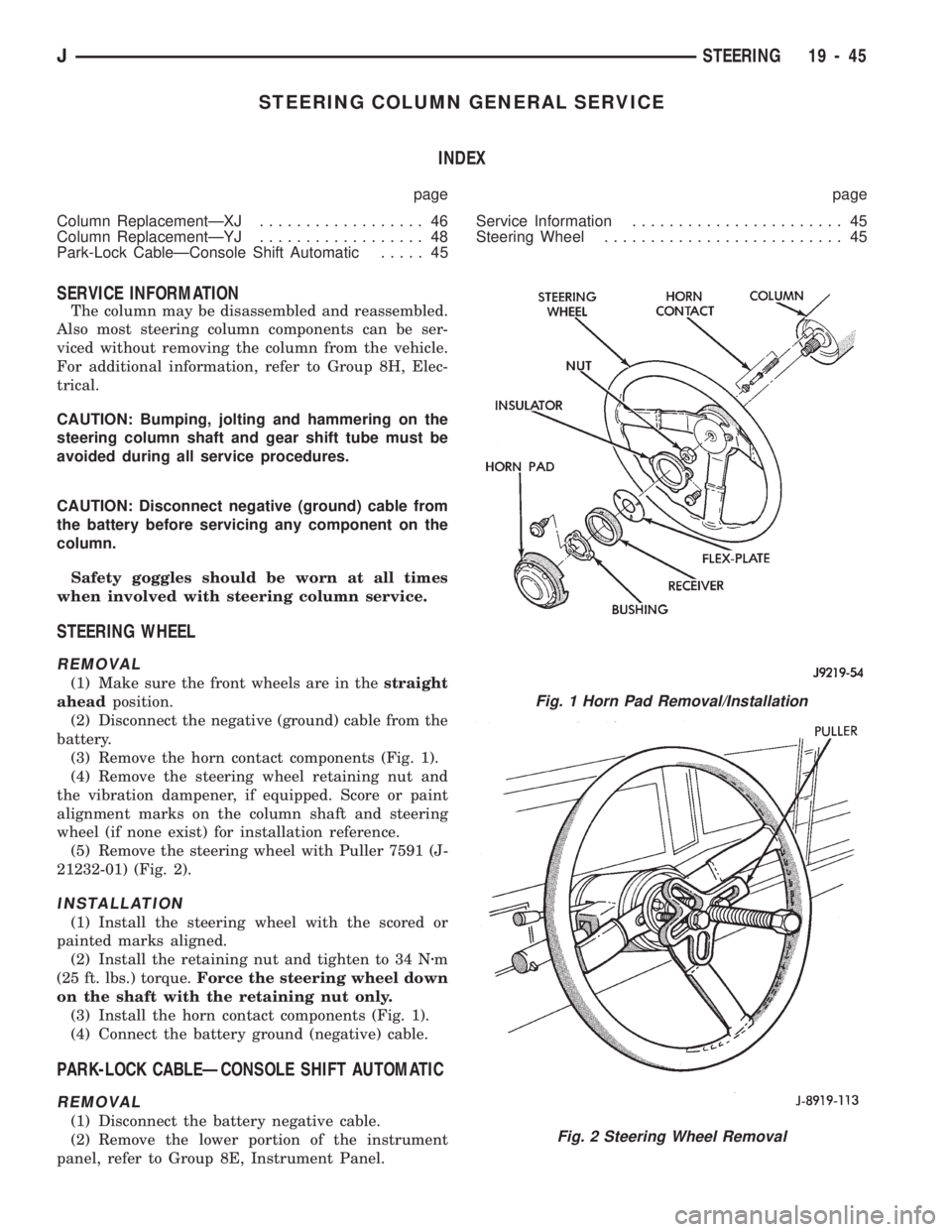
(3) Remove the horn contact components (Fig. 1).
(4) Remove the steering wheel retaining nut and
the vibration dampener, if equipped. Score or paint
alignment marks on the column shaft and steering
wheel (if none exist) for installation reference.
(5) Remove the steering wheel with Puller 7591 (J-
21232-01) (Fig. 2).
INSTALLATION
(1) Install the steering wheel with the scored or
painted marks aligned.
(2) Install the retaining nut and tighten to 34 Nzm
(25 ft. lbs.) torque.Force the steering wheel down
on the shaft with the retaining nut only.
(3) Install the horn contact components (Fig. 1).
(4) Connect the battery ground (negative) cable.
PARK-LOCK CABLEÐCONSOLE SHIFT AUTOMATIC
REMOVAL
(1) Disconnect the battery negative cable.
(2) Remove the lower portion of the instrument
panel, refer to Group 8E, Instrument Panel.
Fig. 1 Horn Pad Removal/Installation
Fig. 2 Steering Wheel Removal
JSTEERING 19 - 45