1994 JEEP CHEROKEE index
[x] Cancel search: indexPage 506 of 1784
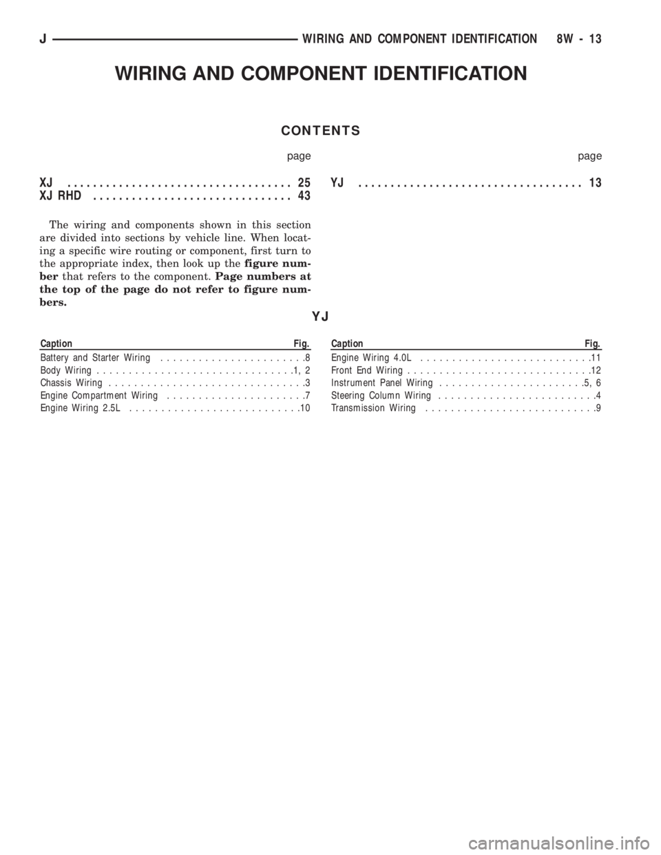
WIRING AND COMPONENT IDENTIFICATION
CONTENTS
page page
XJ ................................... 25
XJ RHD ............................... 43YJ ................................... 13
The wiring and components shown in this section
are divided into sections by vehicle line. When locat-
ing a specific wire routing or component, first turn to
the appropriate index, then look up thefigure num-
berthat refers to the component.Page numbers at
the top of the page do not refer to figure num-
bers.
YJ
Caption Fig.
Battery and Starter Wiring.......................8
Body Wiring...............................1,2
Chassis Wiring...............................3
Engine Compartment Wiring......................7
Engine Wiring 2.5L...........................10Caption Fig.
Engine Wiring 4.0L...........................11
Front End Wiring.............................12
Instrument Panel Wiring.......................5,6
Steering Column Wiring.........................4
Transmission Wiring...........................9
JWIRING AND COMPONENT IDENTIFICATION 8W - 13
Page 546 of 1784
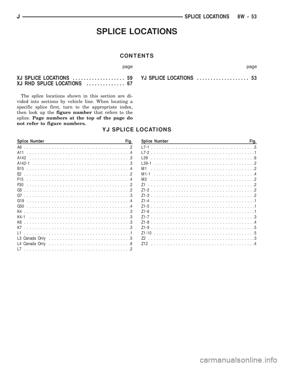
SPLICE LOCATIONS
CONTENTS
page page
XJ SPLICE LOCATIONS................... 59
XJ RHD SPLICE LOCATIONS.............. 67YJ SPLICE LOCATIONS................... 53
The splice locations shown in this section are di-
vided into sections by vehicle line. When locating a
specific splice first, turn to the appropriate index,
then look up thefigure numberthat refers to the
splice.Page numbers at the top of the page do
not refer to figure numbers.
YJ SPLICE LOCATIONS
Splice Number Fig.
A6 .......................................2
A11 ......................................4
A142.....................................3
A142-1....................................3
B15 ......................................4
E2 .......................................2
F15 ......................................4
F30 ......................................2
G5 .......................................2
G7 .......................................3
G19 ......................................4
G50 ......................................4
K4 .......................................3
K4-1.....................................3
K6 .......................................3
K7 .......................................3
L1 .......................................1
L3 Canada Only..............................5
L4 Canada Only..............................6
L7 .......................................2Splice Number Fig.
L7-1......................................5
L7-2......................................1
L39 ......................................6
L39-1.....................................2
M1 ......................................2
M1-1.....................................4
M2 ......................................2
Z1 .......................................2
Z1-2......................................2
Z1-3......................................2
Z1-4......................................1
Z1-5......................................1
Z1-6......................................1
Z1-7......................................3
Z1-8......................................4
Z1-9......................................5
Z1-10.....................................5
Z2 .......................................3
Z12 ......................................4
JSPLICE LOCATIONS 8W - 53
Page 566 of 1784
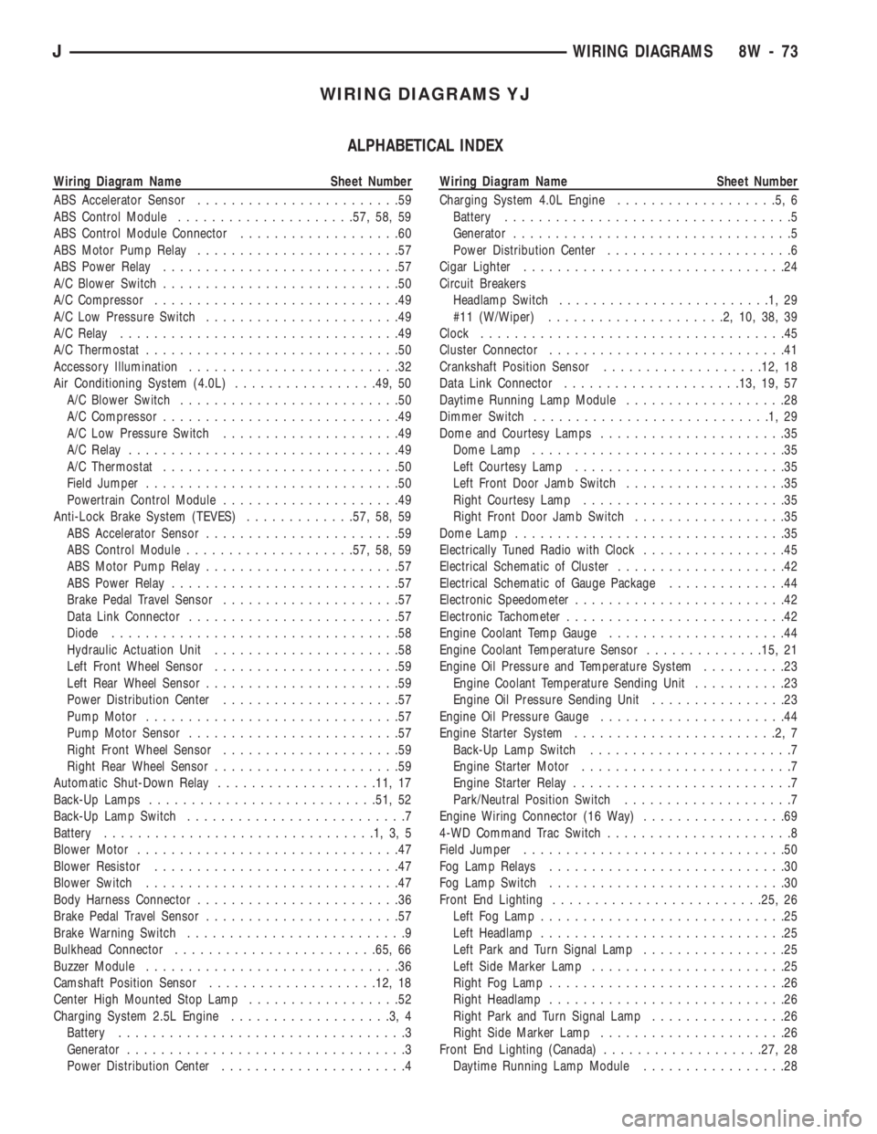
WIRING DIAGRAMS YJ
ALPHABETICAL INDEX
Wiring Diagram Name Sheet Number
ABS Accelerator Sensor........................59
ABS Control Module.....................57, 58, 59
ABS Control Module Connector...................60
ABS Motor Pump Relay........................57
ABS Power Relay............................57
A/C Blower Switch............................50
A/C Compressor.............................49
A/C Low Pressure Switch.......................49
A/C Relay.................................49
A/C Thermostat..............................50
Accessory Illumination.........................32
Air Conditioning System (4.0L).................49, 50
A/C Blower Switch..........................50
A/C Compressor............................49
A/C Low Pressure Switch.....................49
A/C Relay................................49
A/C Thermostat............................50
Field Jumper..............................50
Powertrain Control Module.....................49
Anti-Lock Brake System (TEVES).............57, 58, 59
ABS Accelerator Sensor.......................59
ABS Control Module....................57, 58, 59
ABS Motor Pump Relay.......................57
ABS Power Relay...........................57
Brake Pedal Travel Sensor.....................57
Data Link Connector.........................57
Diode..................................58
Hydraulic Actuation Unit......................58
Left Front Wheel Sensor......................59
Left Rear Wheel Sensor.......................59
Power Distribution Center.....................57
Pump Motor..............................57
Pump Motor Sensor.........................57
Right Front Wheel Sensor.....................59
Right Rear Wheel Sensor......................59
Automatic Shut-Down Relay...................11, 17
Back-Up Lamps...........................51, 52
Back-Up Lamp Switch..........................7
Battery................................1,3,5
Blower Motor...............................47
Blower Resistor.............................47
Blower Switch..............................47
Body Harness Connector........................36
Brake Pedal Travel Sensor.......................57
Brake Warning Switch..........................9
Bulkhead Connector........................65, 66
Buzzer Module..............................36
Camshaft Position Sensor....................12, 18
Center High Mounted Stop Lamp..................52
Charging System 2.5L Engine...................3,4
Battery..................................3
Generator.................................3
Power Distribution Center......................4Wiring Diagram Name Sheet Number
Charging System 4.0L Engine...................5,6
Battery..................................5
Generator.................................5
Power Distribution Center......................6
Cigar Lighter...............................24
Circuit Breakers
Headlamp Switch.........................1,29
#11 (W/Wiper).....................2,10,38,39
Clock....................................45
Cluster Connector............................41
Crankshaft Position Sensor...................12, 18
Data Link Connector.....................13, 19, 57
Daytime Running Lamp Module...................28
Dimmer Switch............................1,29
Dome and Courtesy Lamps......................35
Dome Lamp..............................35
Left Courtesy Lamp.........................35
Left Front Door Jamb Switch...................35
Right Courtesy Lamp........................35
Right Front Door Jamb Switch..................35
Dome Lamp................................35
Electrically Tuned Radio with Clock.................45
Electrical Schematic of Cluster....................42
Electrical Schematic of Gauge Package..............44
Electronic Speedometer.........................42
Electronic Tachometer..........................42
Engine Coolant Temp Gauge.....................44
Engine Coolant Temperature Sensor..............15, 21
Engine Oil Pressure and Temperature System..........23
Engine Coolant Temperature Sending Unit...........23
Engine Oil Pressure Sending Unit................23
Engine Oil Pressure Gauge......................44
Engine Starter System........................2,7
Back-Up Lamp Switch........................7
Engine Starter Motor.........................7
Engine Starter Relay..........................7
Park/Neutral Position Switch....................7
Engine Wiring Connector (16 Way).................69
4-WD Command Trac Switch......................8
Field Jumper...............................50
Fog Lamp Relays............................30
Fog Lamp Switch............................30
Front End Lighting.........................25, 26
Left Fog Lamp.............................25
Left Headlamp.............................25
Left Park and Turn Signal Lamp.................25
Left Side Marker Lamp.......................25
Right Fog Lamp............................26
Right Headlamp............................26
Right Park and Turn Signal Lamp................26
Right Side Marker Lamp......................26
Front End Lighting (Canada)...................27, 28
Daytime Running Lamp Module.................28
JWIRING DIAGRAMS 8W - 73
Page 642 of 1784
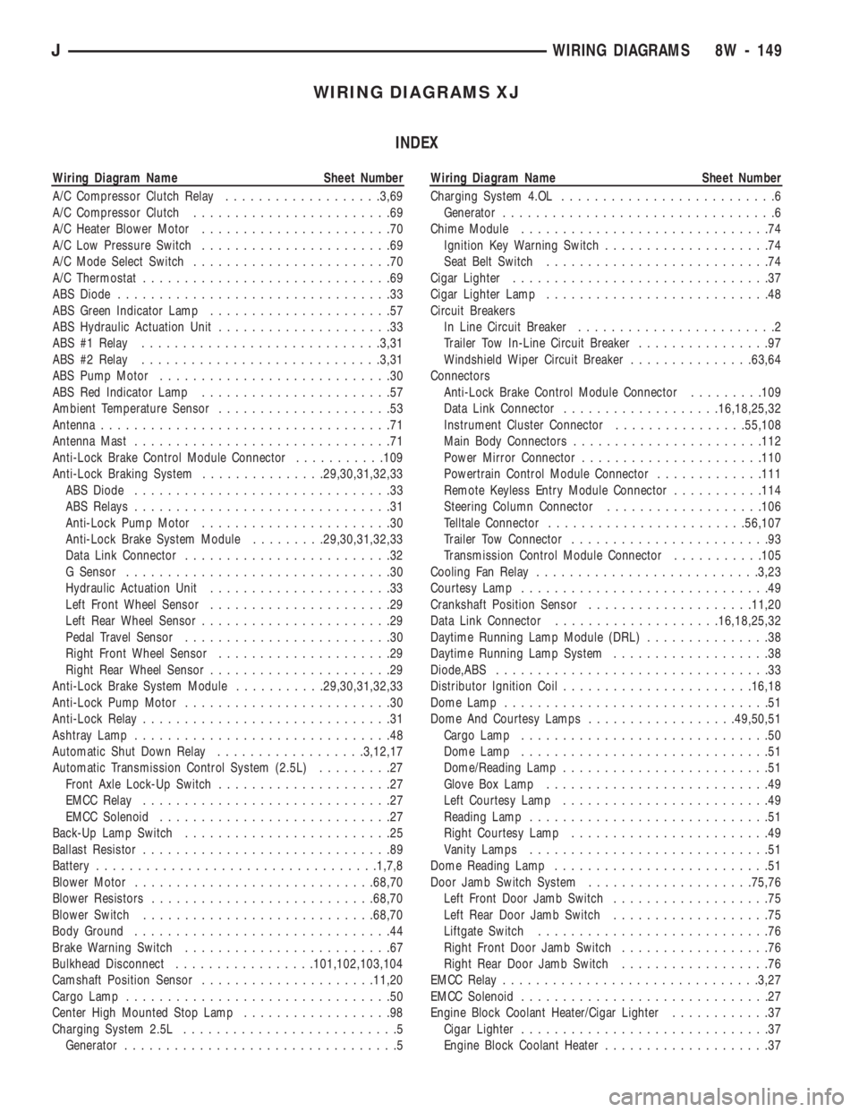
WIRING DIAGRAMS XJ
INDEX
Wiring Diagram Name Sheet Number
A/C Compressor Clutch Relay...................3,69
A/C Compressor Clutch........................69
A/C Heater Blower Motor.......................70
A/C Low Pressure Switch.......................69
A/C Mode Select Switch........................70
A/C Thermostat..............................69
ABS Diode.................................33
ABS Green Indicator Lamp......................57
ABS Hydraulic Actuation Unit.....................33
ABS #1 Relay.............................3,31
ABS #2 Relay.............................3,31
ABS Pump Motor............................30
ABS Red Indicator Lamp.......................57
Ambient Temperature Sensor.....................53
Antenna...................................71
Antenna Mast...............................71
Anti-Lock Brake Control Module Connector...........109
Anti-Lock Braking System...............29,30,31,32,33
ABS Diode...............................33
ABS Relays...............................31
Anti-Lock Pump Motor.......................30
Anti-Lock Brake System Module.........29,30,31,32,33
Data Link Connector.........................32
G Sensor................................30
Hydraulic Actuation Unit......................33
Left Front Wheel Sensor......................29
Left Rear Wheel Sensor.......................29
Pedal Travel Sensor.........................30
Right Front Wheel Sensor.....................29
Right Rear Wheel Sensor......................29
Anti-Lock Brake System Module...........29,30,31,32,33
Anti-Lock Pump Motor.........................30
Anti-Lock Relay..............................31
Ashtray Lamp...............................48
Automatic Shut Down Relay..................3,12,17
Automatic Transmission Control System (2.5L).........27
Front Axle Lock-Up Switch.....................27
EMCC Relay..............................27
EMCC Solenoid............................27
Back-Up Lamp Switch.........................25
Ballast Resistor..............................89
Battery..................................1,7,8
Blower Motor.............................68,70
Blower Resistors...........................68,70
Blower Switch............................68,70
Body Ground...............................44
Brake Warning Switch.........................67
Bulkhead Disconnect.................101,102,103,104
Camshaft Position Sensor.....................11,20
Cargo Lamp................................50
Center High Mounted Stop Lamp..................98
Charging System 2.5L..........................5
Generator.................................5Wiring Diagram Name Sheet Number
Charging System 4.OL..........................6
Generator.................................6
Chime Module..............................74
Ignition Key Warning Switch....................74
Seat Belt Switch...........................74
Cigar Lighter...............................37
Cigar Lighter Lamp...........................48
Circuit Breakers
In Line Circuit Breaker........................2
Trailer Tow In-Line Circuit Breaker................97
Windshield Wiper Circuit Breaker...............63,64
Connectors
Anti-Lock Brake Control Module Connector.........109
Data Link Connector...................16,18,25,32
Instrument Cluster Connector................55,108
Main Body Connectors.......................112
Power Mirror Connector......................110
Powertrain Control Module Connector.............111
Remote Keyless Entry Module Connector...........114
Steering Column Connector...................106
Telltale Connector........................56,107
Trailer Tow Connector........................93
Transmission Control Module Connector...........105
Cooling Fan Relay...........................3,23
Courtesy Lamp..............................49
Crankshaft Position Sensor....................11,20
Data Link Connector....................16,18,25,32
Daytime Running Lamp Module (DRL)...............38
Daytime Running Lamp System...................38
Diode,ABS.................................33
Distributor Ignition Coil.......................16,18
Dome Lamp................................51
Dome And Courtesy Lamps..................49,50,51
Cargo Lamp..............................50
Dome Lamp..............................51
Dome/Reading Lamp.........................51
Glove Box Lamp...........................49
Left Courtesy Lamp.........................49
Reading Lamp.............................51
Right Courtesy Lamp........................49
Vanity Lamps.............................51
Dome Reading Lamp..........................51
Door Jamb Switch System....................75,76
Left Front Door Jamb Switch...................75
Left Rear Door Jamb Switch...................75
Liftgate Switch............................76
Right Front Door Jamb Switch..................76
Right Rear Door Jamb Switch..................76
EMCC Relay...............................3,27
EMCC Solenoid..............................27
Engine Block Coolant Heater/Cigar Lighter............37
Cigar Lighter..............................37
Engine Block Coolant Heater....................37
JWIRING DIAGRAMS 8W - 149
Page 764 of 1784
WIRING DIAGRAMS XJ-RHD
INDEX
Wiring Diagram Name Sheet Number
A/C Compressor Clutch........................45
A/C Compressor Clutch Relay....................45
A/C Heater Blower Motor.......................46
A/C Low Pressure Switch.......................45
A/C Mode Selector Switch.......................46
A/C System.............................45, 46
A/C Thermostat..............................45
Antenna Mast...............................47
Ashtray Illumination Lamp.......................26
Automatic Shut Down Relay......................9
Back-up Lamp Switch.........................16
Battery....................................6
Blower Motor............................44, 46
Blower Resistor...........................44, 46
Blower Switch............................44, 46
Body Ground...............................59
Brake Warning Switch.........................42
Camshaft Position Sensor.......................12
Cargo Lamp................................30
Charging System.............................5
Generator.................................5
Check Engine Indicator Lamp..................39, 40
Chime Module..............................43
Chime Module Connector.......................71
Cigar Lighter...............................58
Circuit Breakers
Windshield Wiper Circuit Breaker...............2,33
Connectors
Chime Module Connector......................71
Dash to Instrument Panel Connector A.............64
Dash to Instrument Panel Connector B.............65
Dash to Instrument Panel Connector C.............66
Data Link Connector.........................10
Instrument Cluster Connector 16 Way...........37, 69
Main Body Connector 1.......................70
Power Mirror Connector......................61
Powertrain Control Module Connector..............73
Steering Column Connector 11 Way...............67
Telltale Connector........................38, 68
Transmission Control Module Connector............72
Transmission Data Link Connector................17
Coolant Temperature Switch......................16
Crankshaft Position Sensor......................12
Dash to Instrument Panel Connector A..............64
Dash to Instrument Panel Connector B..............65
Dash to Instrument Panel Connector C..............66
Data Link Connector..........................10
Distributor Ignition Coil........................10
Dome Lamp................................31
Dome and Courtesy Lamps.................29, 30, 31
Cargo Lamp..............................30
Dome Lamp..............................31Wiring Diagram Name Sheet Number
Dome/Reading Lamp.........................31
Glove Box Lamp...........................29
Reading Lamp.............................31
Vanity Lamps.............................31
Dome/Reading Lamp..........................31
Door Jamb Switch System....................49, 50
Left Front Door Jamb Switch...................50
Left Rear Door Jamb Switch...................50
Liftgate Switch............................46
Right Front Door Jamb Switch..................49
Right Rear Door Jamb Switch..................49
Electronic Fuel Injection
Ignition System................9,10,11,12,13,14
Automatic Shut Down Relay.....................9
Camshaft Position Sensor.....................12
Crankshaft Position Sensor.....................12
Data Link Connector.........................10
Distributor Ignition Coil.......................10
Engine Coolant Temperature Sensor...............11
Fuel Injectors.............................14
Fuel Pump Relay............................9
Heated Oxygen Sensor.......................13
Idle Air Control Motor........................14
Intake Air Temp Sensor.......................11
Map Sensor..............................11
Powertrain Control Module........9,10,11,12,13,14
Throttle Position (Sensor).....................11
Engine Block Heater...........................58
Engine Coolant Temperature Sensor................11
Engine Coolant Temperature Switch.................15
Engine Oil Pressure and Temperature System..........15
Engine Oil Pressure Switch......................15
Engine Starter System..........................6
Battery..................................6
Engine Starter Motor.........................6
Engine Starter Relay..........................6
Fan Control Relay...........................3,7
Fog Lamp Illumination Lamp.....................20
Fog Lamp Relay.............................21
Fog Lamp Switch............................20
4WD Select Trac Indicator Lamp................39, 40
Front Axle Switch............................16
Front End Lighting.........................21, 22
Fog Lamp Relay...........................21
Left Fog Lamp.............................21
Left Headlamp.............................21
Left Park/Turn Signal Lamp....................21
Left Side Marker Lamp.......................21
Right Fog Lamp............................22
Right Headlamp............................22
Right Park/Turn Signal Lamp...................22
Right Side Marker Lamp......................22
Front Wipers/Washer - Intermittent..............33, 34
JWIRING DIAGRAMS 8W - 271
Page 842 of 1784
ENGINES
CONTENTS
page page
2.5L ENGINE SERVICE PROCEDURES....... 9
4.0L ENGINE SERVICE PROCEDURES...... 50ENGINE DIAGNOSIS...................... 5
STANDARD SERVICE PROCEDURES......... 1
STANDARD SERVICE PROCEDURES
INDEX
page page
Engine Performance....................... 2
Form-In-Place Gaskets..................... 1
Honing Cylinder Bores..................... 2
Hydrostatic Lock.......................... 4Measuring with Plastigage................... 3
Repair Damaged or Worn Threads............ 4
Service Engine Assembly (Short Block)......... 4
FORM-IN-PLACE GASKETS
There are several places where form-in-place gas-
kets are used on the engine.DO NOT use form-in-
place gasket material unless specified.Care must
be taken when applying form-in-place gaskets. Bead
size, continuity and location are of great importance.
Too thin a bead can result in leakage while too much
can result in spill-over. A continuous bead of the
proper width is essential to obtain a leak-free joint.
Two types of form-in-place gasket materials are
used in the engine area (Mopar Silicone Rubber Ad-
hesive Sealant and Mopar Gasket Maker). Each have
different properties and cannot be used interchange-
ably.
MOPAR SILICONE RUBBER ADHESIVE
SEALANT
Mopar Silicone Rubber Adhesive Sealant, normally
black in color, is available in 3 ounce tubes. Moisture
in the air causes the sealant material to cure. This
material is normally used on flexible metal flanges.
It has a shelf life of a year and will not properly cure
if over aged. Always inspect the package for the ex-
piration date before use.
MOPAR GASKET MAKER
Mopar Gasket Maker, normally red in color, is
available in 6 cc tubes. This anaerobic type gasket
material cures in the absence of air when squeezed
between smooth machined metallic surfaces. It will
not cure if left in the uncovered tube. DO NOT use
on flexible metal flanges.
SURFACE PREPARATION
Parts assembled with form-in-place gaskets may be
disassembled without unusual effort. In some in-
stances, it may be necessary to lightly tap the part
with a mallet or other suitable tool to break the seal
between the mating surfaces. A flat gasket scraper
may also be lightly tapped into the joint but care
must be taken not to damage the mating surfaces.
Scrape or wire brush all gasket surfaces to remove
all loose material. Inspect stamped parts to ensure
gasket rails are flat. Flatten rails with a hammer on
a flat plate, if required. Gasket surfaces must be free
of oil and dirt. Make sure the old gasket material is
removed from blind attaching holes.
GASKET APPLICATION
Assembling parts using a form-in-place gasket re-
quires care.
Mopar Silicone Rubber Adhesive Sealant should be
applied in a continuous bead approximately 3 mm
(0.12 inch) in diameter. All mounting holes must be
circled. For corner sealing,a3or6mm(1/8 or 1/4
inch) drop is placed in the center of the gasket con-
tact area. Uncured sealant may be removed with a
shop towel. Components should be torqued in place
while the sealant is still wet to the touch (within 10
minutes). The use of a locating dowel is recom-
mended during assembly to prevent smearing the
material off location.
Mopar Gasket Maker should be applied sparingly
to one gasket surface. The sealant diameter should
be 1.00 mm (0.04 inch) or less. Be certain the mate-
rial surrounds each mounting hole. Excess material
JENGINES 9 - 1
Page 850 of 1784
2.5L ENGINE SERVICE PROCEDURES
INDEX
page page
Camshaft............................... 29
Camshaft Pin Replacement................. 31
Crankshaft Main Bearings.................. 40
Cylinder Block........................... 45
Engine AssemblyÐXJ Vehicles.............. 14
Engine AssemblyÐYJ Vehicles.............. 16
Engine Cylinder Head..................... 19
Engine Cylinder Head Cover................ 18
Engine Damper.......................... 13
Engine MountÐRear...................... 12
Engine MountsÐFront..................... 10
General Information........................ 9
Hydraulic Tappets........................ 24Oil Pan ................................ 32
Oil Pump............................... 33
Pistons and Connecting Rods............... 34
Rear Main Oil Seals...................... 44
Rocker Arms............................ 19
Specifications........................... 47
Timing Case Cover....................... 27
Timing Case Cover Oil Seal Replacement...... 26
Timing Chain and Sprockets................ 28
Valve Springs and Oil Seals................ 21
Valve Timing............................ 26
Valves and Valve Springs.................. 22
Vibration Damper........................ 26
GENERAL INFORMATION
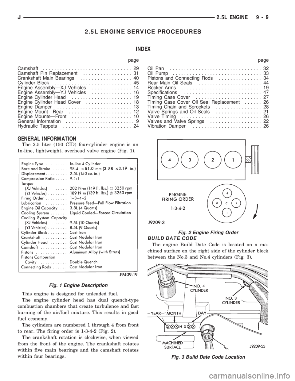
The 2.5 liter (150 CID) four-cylinder engine is an
In-line, lightweight, overhead valve engine (Fig. 1).
This engine is designed for unleaded fuel.
The engine cylinder head has dual quench-type
combustion chambers that create turbulence and fast
burning of the air/fuel mixture. This results in good
fuel economy.
The cylinders are numbered 1 through 4 from front
to rear. The firing order is 1-3-4-2 (Fig. 2).
The crankshaft rotation is clockwise, when viewed
from the front of the engine. The crankshaft rotates
within five main bearings and the camshaft rotates
within four bearings.
BUILD DATE CODE
The engine Build Date Code is located on a ma-
chined surface on the right side of the cylinder block
between the No.3 and No.4 cylinders (Fig. 3).
Fig. 1 Engine Description
Fig. 2 Engine Firing Order
Fig. 3 Build Date Code Location
J2.5L ENGINE 9 - 9
Page 867 of 1784

least 1 600 km (1,000 miles). The oil supplement
need not be drained until the next scheduled oil
change.
(7) Install the engine cylinder head cover.
VALVE TIMING
Disconnect the spark plug wires and remove the
spark plugs.
Remove the engine cylinder head cover.
Remove the capscrews, bridge and pivot assembly,
and rocker arms from above the No.1 cylinder.
Alternately loosen each capscrew, one turn at a
time, to avoid damaging the bridge.
Rotate the crankshaft until the No.4 piston is at
top dead center (TDC) on the compression stroke.
Rotate the crankshaft counterclockwise (viewed
from the front of the engine) 90É.
Install a dial indicator on the end of the No.1 cyl-
inder intake valve push rod. Use rubber tubing to se-
cure the indicator stem on the push rod.
Set the dial indicator pointer at zero.
Rotate the crankshaft clockwise (viewed from the
front of the engine) until the dial indicator pointer
indicates 0.305 mm (0.012 inch) travel distance (lift).
The timing notch index on the vibration damper
should be aligned with the TDC mark on the timing
degree scale.
If the timing notch is more than 13 mm (1/2 inch)
away from the TDC mark in either direction, the
valve timing is incorrect.
If the valve timing is incorrect, the cause may be a
broken camshaft pin. It is not necessary to replace
the camshaft because of pin failure. A spring pin is
available for service replacement.
VIBRATION DAMPER
REMOVAL
(1) Disconnect negative cable from battery.
(2) Remove the serpentine drive belt and fan
shroud.
(3) Remove the vibration damper retaining bolt
and washer.
(4) Use Vibration Damper Removal Tool 8068 to
remove the damper from the crankshaft (Fig. 1).
INSTALLATION
(1) Apply Mopar Silicone Rubber Adhesive Sealant
to the keyway in the crankshaft and insert the key.
With the key in position, align the keyway on the vi-
bration damper hub with the crankshaft key and tap
the damper onto the crankshaft.
(2) Install the vibration damper retaining bolt and
washer.
(3) Tighten the damper retaining bolt to 108 Nzm
(80 ft. lbs.) torque.(4) Install the serpentine drive belt and tighten to
the specified tension (refer to Group 7, Cooling Sys-
tems for the proper specifications and procedures).
(5) Connect negative cable to battery.
TIMING CASE COVER OIL SEAL REPLACEMENT
This procedure is done with the timing case cover
installed.
(1) Disconnect negative cable from battery.
(2) Remove the serpentine drive belt.
(3) Remove the vibration damper.
(4) Remove the radiator shroud.
(5) Carefully remove the oil seal (Fig. 2). Make
sure seal bore is clean.
(6) Position the replacement oil seal on Timing
Case Cover Alignment and Seal Installation Tool
6139 with seal open end facing inward. Apply a light
film of Perfect Seal, or equivalent, on the outside di-
ameter of the seal. Lightly coat the crankshaft with
engine oil.
(7) Position the tool and seal over the end of the
crankshaft and insert a draw screw tool into Seal In-
stallation Tool 6139 (Fig. 3). Tighten the nut against
the tool until it contacts the cover.
Fig. 1 Vibration Damper Removal Tool 8068
Fig. 2 Timing Case Cover Oil Seal Removal
9 - 26 2.5L ENGINEJ