1994 JEEP CHEROKEE index
[x] Cancel search: indexPage 949 of 1784
YJ FRAME
INDEX
page page
Frame Alignment......................... 10
Frame Inspection/Measurements............. 10Frame Repair Service..................... 13
General Information........................ 8
GENERAL INFORMATION
FUNCTIONS
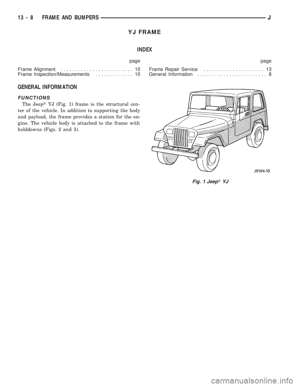
The JeeptYJ (Fig. 1) frame is the structural cen-
ter of the vehicle. In addition to supporting the body
and payload, the frame provides a station for the en-
gine. The vehicle body is attached to the frame with
holddowns (Figs. 2 and 3).
Fig. 1 JeepTYJ
13 - 8 FRAME AND BUMPERSJ
Page 955 of 1784

YJ BUMPERS AND FRAME ATTACHED COMPONENTS
INDEX
page page
Generator Splash Shield................... 14
Body.................................. 18
Engine Front Support Cushion............... 15
Frame Crossmember Cover................. 14
Front Bumper........................... 14
Fuel and Brake Fluid Tube Retainer Clip....... 16
Fuel Filter Shield and Bracket............... 17
Fuel Tank Skid Plate...................... 16Muffler and Tailpipe Heat Shields............ 17
Muffler/Tailpipe Hanger Bracket.............. 16
Rear Bumper............................ 18
Rear Jounce Bumper..................... 18
Service Information....................... 14
Tow Hooks............................. 14
Transfer Case Skid Plate.................. 15
SERVICE INFORMATION
In some cases, components in the following proce-
dures either support, or are hidden by other compo-
nents.
FRONT BUMPER
The YJ front bumper is a one-piece rail (Fig. 1). A
front crossmember cover (Fig. 1) is also installed on
all YJ vehicles.
BUMPER REMOVAL
(1) Disconnect and remove the fog lamps, if
equipped.
(2) Remove the nuts and bolts that retain the
bumper extensions to the bumper rail and remove
the extensions.
(3) Remove the nuts and bolts that attach the
bumper rail/tow hooks to the frame rails.(4) Remove the bumper rail from the frame rails.
BUMPER INSTALLATION
(1) Position the front bumper on the frame rails.
(2) Install the bolts and attach the front bumper
rail (and tow hooks, if equipped) to the frame rails.
(3) Tighten the bolts to 102 Nzm (75 ft-lbs) torque.
(4) Position the bumper extensions on the bumper
rail and install the retaining bolts.
(5) Tighten the bolts to 104 Nzm (77 ft-lbs) torque.
(6) Install the fog lamps, if equipped.
FRAME CROSSMEMBER COVER
REMOVAL
(1) Remove the screws that attach the crossmem-
ber cover and support to the frame rails.
(2) Remove the crossmember cover and support
from the frame rails.
INSTALLATION
(1) Position the support and crossmember cover on
the frame rails.
(2) Install the attaching screws.
(3) Tighten the screws to 8 Nzm (72 in-lbs) torque.
TOW HOOKS
REMOVAL
(1) Remove the two bolts that attach the tow hook
to the bumper rail and to the frame rail.
(2) Remove the tow hook.
INSTALLATION
(1) Position the tow hook on the bumper rail and
frame rail.
(2) Install the attaching bolts.
(3) Tighten the bolts to 102 Nzm (75 ft-lbs) torque.
GENERATOR SPLASH SHIELD
REMOVAL
(1) Remove the shield retaining nut and washer
(Fig. 2) from the engine oil pan stud (2.5L engines
only).
Fig. 1 Front Bumper Rail, Crossmember Cover &
Tow Hooks
13 - 14 FRAME AND BUMPERSJ
Page 963 of 1784
line. You may encounter fuels containing 3 percent
or more methanol along with other alcohols called co-
solvents.
Problems that are the result of using methanol/gas-
oline blends are not the responsibility of Chrysler
Corporation. They may not be covered by the vehicle
warranty.
MTBE/ETBE
Gasoline and MTBE (Methyl Tertiary Butyl Ether)
blends are a mixture of unleaded gasoline and up to
15 percent MTBE. Gasoline and ETBE (Ethyl Ter-
tiary Butyl Ether) are blends of gasoline and up to
17 percent ETBE. Gasoline blended with MTBE or
ETBE may be used in your vehicle.CLEAN AIR GASOLINE
Many gasolines are now being blended that con-
tribute to cleaner air, especially in those areas of the
country where air pollution levels are high. These
new blends provide a cleaner burning fuel and some
are referred to asReformulated Gasoline.
In areas of the country where carbon monoxide lev-
els are high, gasolines are being treated with oxy-
genated materials such as MTBE, ETBE and
ethanol.
Chrysler Corporation supports these efforts toward
cleaner air and recommends that you use these gas-
olines as they become available.
FUEL DELIVERY SYSTEM
INDEX
page page
Fuel Filter............................... 8
Fuel Pressure Leak Down Test............... 7
Fuel Pressure Release Procedure............. 5
Fuel Pump Capacity Test................... 7
Fuel Pump Electrical Control................. 5Fuel Pump Module........................ 2
Fuel System Pressure Test.................. 5
Fuel Tubes/Lines/Hoses and Clamps........... 9
Quick-Connect Fittings..................... 9
FUEL PUMP MODULE
The fuel pump module is installed in the top of the
fuel tank. The fuel pump module contains the follow-
ing components:
²Electric fuel pump
²Fuel pump reservoir
²In-tank fuel filter
²Fuel gauge sending unit
²Fuel supply and return tube connections
The fuel pump used on all vehicles is a gear/rotor
type pump. It is driven by a permanent magnet 12
volt electric motor that is immersed in the fuel tank.
The electrical pump is integral with the fuel sender
unit. The pump/sender assembly is installed inside
the fuel tank.
The fuel pump has a check valve at the outlet end
that consists of a ball held against a seat by force ap-
plied from a spring. When the pump is operating,
fuel pressure overcomes spring pressure and forces
the ball off its seat, allowing fuel to flow. When the
pump is not operating, spring pressure forces the ball
back against the seat preventing fuel backflow
through the pump.
Fuel system pressure is maintained at approxi-
mately 214 kPa (31 psi). This is when the pump is
operating and vacuum is supplied to the fuel pres-
sure regulator. If vacuum is not supplied to the pres-
sure regulator, fuel pressure will be approximately
55-69 kPa (8-10 psi) higher. This may be due to a
broken or clogged vacuum line. When the fuel pumpis not operating, system fuel pressure of 131-269 kPa
(19-39 psi) is maintained. This is done by the fuel
pump outlet check valve and the vacuum assisted
fuel pressure regulator.
REMOVALÐXJ MODELS
The fuel pump/gauge sender unit assembly can be
removed from the fuel tank without removing the
tank from the vehicle.
WARNING: THE FUEL SYSTEM IS UNDER A CON-
STANT PRESSURE (EVEN WITH THE ENGINE OFF).
BEFORE SERVICING THE FUEL PUMP MODULE,
THE FUEL SYSTEM PRESSURE MUST BE RE-
LEASED. REFER TO THE FUEL PRESSURE RE-
LEASE PROCEDURE IN THIS GROUP.
WARNING: EXTINGUISH ALL TOBACCO SMOKING
PRODUCTS BEFORE SERVICING THE FUEL SYS-
TEM. KEEP OPEN FLAME AWAY FROM FUEL SYS-
TEM COMPONENTS.
(1) Remove fuel filler cap. Perform the Fuel Pres-
sure Release Procedure as outlined in this group.
(2) Disconnect negative battery cable.
(3) Using an approved portable gasoline siphon/
storage tank, drain fuel tank until fuel level is below
one quarter (1/4) full.
(4) Raise and support vehicle.
14 - 2 FUEL SYSTEMJ
Page 973 of 1784
FUEL TANKS
INDEX
page page
Fuel Gauge Sending Unit.................. 15
Fuel Tank.............................. 12
Fuel Tank Filler Tube Cap................. 12
Fuel Tank Pressure Relief/Rollover Valve...... 15General Information....................... 12
Heat Shields............................ 12
No-Lead Fuel Tank Filler Tube.............. 12
GENERAL INFORMATION
All vehicles pass a full 360 degree rollover test
without fuel leakage. To accomplish this, fuel and
vapor flow controls are required for all fuel tank con-
nections.
All models are equipped with a pressure relief/roll-
over valve mounted in the top of the fuel pump mod-
ule. The return line from the fuel pump to the fuel
tank contains a one-way check valve.
An evaporative control system prevents raw fuel
vapor from escaping into the atmosphere. Fuel va-
pors from the fuel tank are collected in the EVAP
canister. When the engine is operating, the vapors
are drawn into the intake manifold to be used in
combustion. Refer to Group 25, Emission Control
System for more information.
Inspect all hose/tube connections for completeness.
Be sure that leaks are not present. Replace any hose
that is cracked, scuffed, swelled, has rubbed against
other vehicle components or shows any other sign of
wear that could lead to failure. If it is necessary to
replace a hose, only hose marked EFM/EFI may be
used.
When installing hoses, be sure that they are routed
away from contact with other vehicle components.
The hose clamps used on fuel injected vehicles are
of a special rolled edge construction to prevent the
edge of the clamp from cutting into the hose. Only
these rolled edge type clamps may be used on this
system. Other types of clamps may cut into the hoses
and cause high pressure fuel leaks.
NO-LEAD FUEL TANK FILLER TUBE
All vehicles are designed to operate using Un-
leaded fuels. The diameter of the opening in the fuel
tank filler neck is sized to only accept unleaded fuel
nozzles. Gasoline station pumps for unleaded and
leaded fuels have different size nozzles. Leaded fuel
nozzles are larger in diameter than unleaded nozzles.
The fuel tank filler neck opening is also equipped
with a deflector, which the smaller unleaded nozzle
pushes back upon entering the filler neck. The de-
flector will prevent the larger diameter leaded fuel
nozzles from entering the filler neck and will deflect
fuel away from the filler neck. This happens if filling
of the tank with leaded fuel is attempted.
A label is attached to the instrument panel under
the fuel gauge that reads UNLEADED FUEL ONLY
as a reminder to the driver. A similar label is located
near the fuel tank filler.
FUEL TANK FILLER TUBE CAP
The loss of any fuel or vapor out of the filler neck
is prevented by the use of a safety filler cap. This
will release only under pressure of 10.9 to 13.45 kPa
(1.58 to 1.95 psi). The vacuum release is between .97
and 2.0 kPa (.14 and .29 psi). This cap must be re-
placed by a similar unit if replacement is necessary.
CAUTION: Remove the fuel tank filler tube cap prior
to removing or repairing fuel lines to relieve fuel
tank pressure.
HEAT SHIELDS
The sheet metal heat shields may have to be re-
moved when servicing the fuel tank, fuel lines or va-
por vent line. The heat shields must be installed to
protect the lines and tank from the heat of the ex-
haust system. Refer to Group 11, Exhaust System
and Intake Manifold for proper installation.
FUEL TANK
WARNING: THE FUEL SYSTEM IS UNDER CON-
STANT FUEL PRESSURE (EVEN WITH THE ENGINE
OFF) OF APPROXIMATELY 131-269 KPA (19-39
PSI). THIS PRESSURE MUST BE RELEASED BE-
FORE SERVICING FUEL TANK.
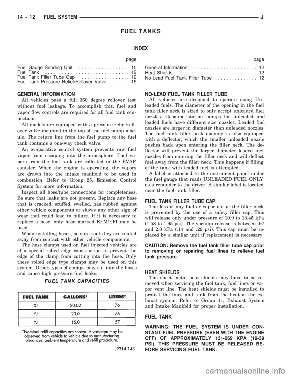
FUEL TANK CAPACITIES
14 - 12 FUEL SYSTEMJ
Page 978 of 1784
MULTI-PORT FUEL INJECTION (MFI)ÐCOMPONENT DESCRIPTION/SYSTEM
OPERATION
INDEX
page page
Air Conditioning (A/C) Clutch RelayÐPCM Output.24
Air Conditioning (A/C) ControlsÐPCM Input.... 19
Auto Shut Down (ASD) RelayÐPCM Output.... 24
Automatic Shut Down (ASD) SenseÐPCM Input . 19
Battery VoltageÐPCM Input................ 19
Brake SwitchÐPCM Input.................. 20
Camshaft Position SensorÐPCM Input........ 20
Crankshaft Position SensorÐPCM Input....... 20
Data Link ConnectorÐPCM Input............ 20
Data Link ConnectorÐPCM Output........... 24
EMR LampÐPCM Output.................. 24
Engine Coolant Temperature SensorÐPCM Input . 21
Extended Idle SwitchÐPCM Input............ 21
Fuel InjectorsÐPCM Output................ 25
Fuel Pressure Regulator................... 30
Fuel Pump RelayÐPCM Output............. 25
Fuel Rail............................... 30
General Information....................... 17
Generator FieldÐPCM Output............... 25
Generator LampÐPCM Output.............. 25
Idle Air Control (IAC) MotorÐPCM Output...... 25
Ignition Circuit SenseÐPCM Input............ 21
Ignition CoilÐPCM Output.................. 26Intake Air Temperature SensorÐPCM Input.... 20
Malfunction Indicator LampÐPCM Output...... 26
Manifold Absolute Pressure (MAP) SensorÐ
PCM Input............................ 21
Open Loop/Closed Loop Modes of Operation . . . 27
Overdrive/Override Switch.................. 22
Oxygen (O2S) SensorÐPCM Input........... 22
Park/Neutral SwitchÐPCM Input............. 22
Power Ground........................... 22
Power Steering Pressure SwitchÐPCM Input . . . 22
Powertrain Control Module (PCM)............ 18
Radiator Fan RelayÐPCM Output............ 26
SCI ReceiveÐPCM Input.................. 22
SCI TransmitÐPCM Output................. 26
Sensor ReturnÐPCM Input................. 23
Shift IndicatorÐPCM Output................ 26
Speed ControlÐPCM Input................. 23
Speed ControlÐPCM Output................ 27
TachometerÐPCM Output.................. 27
Throttle Body............................ 29
Throttle Position Sensor (TPS)ÐPCM Input..... 23
Torque Converter Clutch RelayÐPCM Output . . . 27
Vehicle Speed SensorÐPCM Input........... 23
GENERAL INFORMATION
All 2.5L 4 cylinder and 4.0L 6 cylinder engines are
equipped with sequential Multi-Port Fuel Injection
(MFI). The MFI system provides precise air/fuel ra-
tios for all driving conditions.
The Powertrain Control Module (PCM) operates
the fuel system. The PCM was formerly referred to
as the SBEC or engine controller. The PCM is a pre-
programmed, dual microprocessor digital computer.
It regulates ignition timing, air-fuel ratio, emission
control devices, charging system, speed control, air
conditioning compressor clutch engagement and idle
speed. The PCM can adapt its programming to meet
changing operating conditions.
Powertrain Control Module (PCM) Inputsrep-
resent the instantaneous engine operating conditions.
Air-fuel mixture and ignition timing calibrations for
various driving and atmospheric conditions are pre-
programmed into the PCM. The PCM monitors and
analyzes various inputs. It then computes engine fuel
and ignition timing requirements based on these in-
puts. Fuel delivery control and ignition timing will
then be adjusted accordingly.
Other inputs to the PCM are provided by the brake
light switch, air conditioning select switch and the
speed control switches. All inputs to the PCM are
converted into signals.
Electrically operated fuel injectors spray fuel in
precise metered amounts into the intake port directlyabove the intake valve. The injectors are fired in a
specific sequence by the PCM. The PCM maintains
an air/fuel ratio of 14.7 to 1 by constantly adjusting
injector pulse width. Injector pulse width is the
length of time that the injector opens and sprays fuel
into the chamber. The PCM adjusts injector pulse
width by opening and closing the ground path to the
injector.
Manifold absolute pressure (air density) and engine
rpm (speed) are the primary inputs that determine
fuel injector pulse width. The PCM also monitors
other inputs when adjusting air-fuel ratio.
Inputs That Effect Fuel Injector Pulse Width
²Exhaust gas oxygen content
²Engine coolant temperature
²Manifold absolute pressure (MAP)
²Engine speed
²Throttle position
²Battery voltage
²Air conditioning selection
²Transmission gear selection (automatic transmis-
sions only)
²Speed control
The powertrain control module (PCM) adjusts igni-
tion timing by controlling ignition coil operation. The
ignition coil receives battery voltage when the igni-
tion key is in the run or starter position. The PCM
provides a ground for the ignition coil. The coil dis-
JFUEL SYSTEM 14 - 17
Page 993 of 1784
MULTI-PORT FUEL INJECTION (MFI)ÐGENERAL DIAGNOSIS
INDEX
page page
Automatic Shutdown (ASD) Relay Testing...... 43
Camshaft Position Sensor Test.............. 43
Crankshaft Position Sensor Test............. 44
Diagnostic Trouble Code (DTC).............. 51
DRB Scan Tool.......................... 51
Engine Coolant Temperature Sensor Test...... 43
Extended Idle Switch Test.................. 45
Fuel Pump Relay Testing.................. 44
Fuel System Pressure Test................. 48
General Information....................... 32
Idle Air Control Motor Test................. 46
Injector Test............................ 48
Intake Air Temperature Sensor Test.......... 43Manifold Absolute Pressure (MAP) Sensor Test . 44
On-Board Diagnostics (OBD)................ 48
Oxygen Sensor (O2S) Heating Element Test.... 45
Powertrain Control Module (PCM) 60-Way
Connector............................ 38
RelaysÐOperation/Testing.................. 47
Starter Motor Relay Test................... 48
System Schematics....................... 38
Throttle Position Sensor (TPS) Test.......... 45
Torque Converter Clutch Relay Test.......... 45
Vehicle Speed Sensor Test................. 45
Visual Inspection......................... 32
GENERAL INFORMATION
All 2.5L 4 cylinder and 4.0L 6 cylinder engines are
equipped with sequential Multi-Port Fuel Injection
(MFI). The MFI system provides precise air/fuel ra-
tios for all driving conditions.
VISUAL INSPECTION
A visual inspection for loose, disconnected, or incor-
rectly routed wires and hoses should be made. This
should be done before attempting to diagnose or ser-
vice the fuel injection system. A visual check will
help spot these faults and save unnecessary test and
diagnostic time. A thorough visual inspection will in-
clude the following checks:
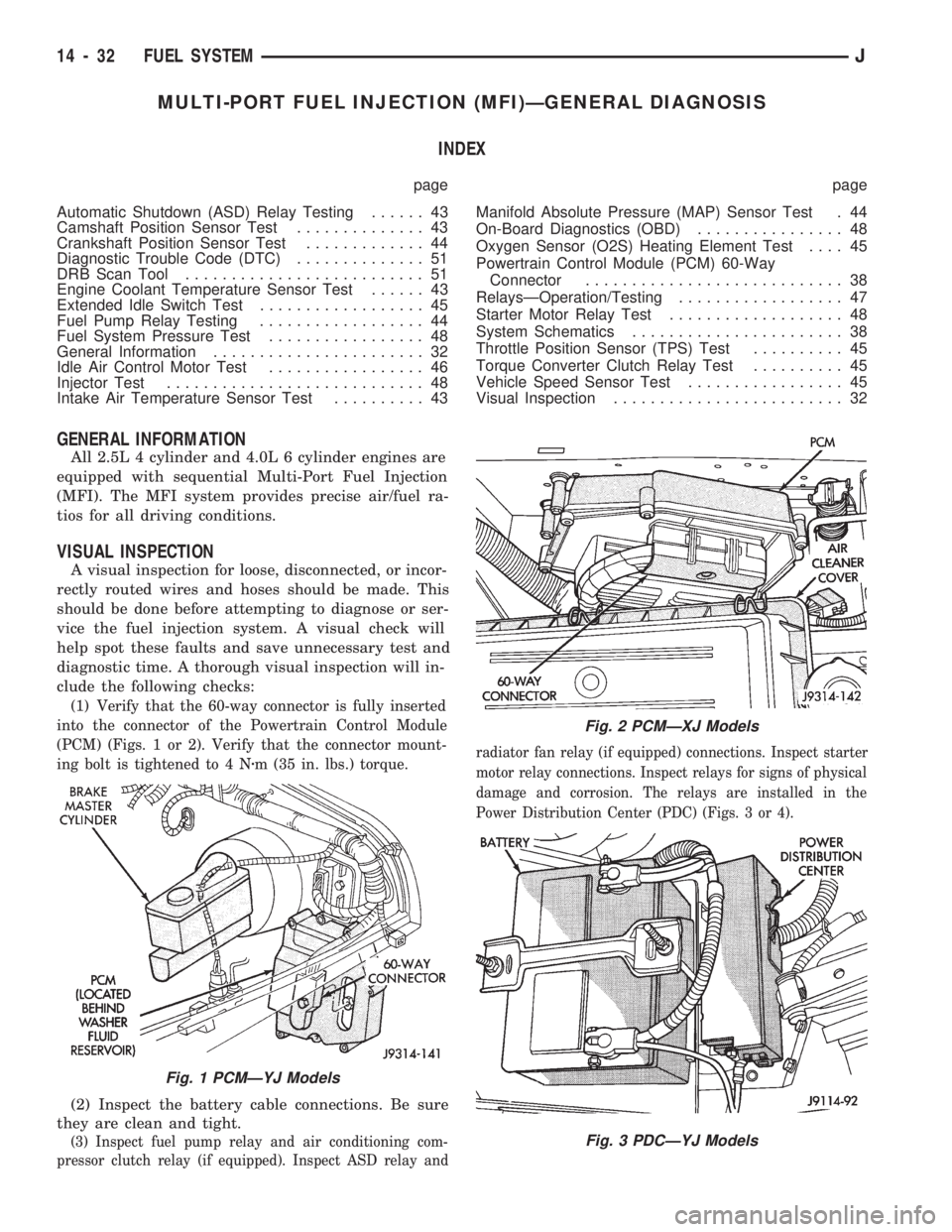
(1) Verify that the 60-way connector is fully inserted
into the connector of the Powertrain Control Module
(PCM) (Figs. 1 or 2). Verify that the connector mount-
ing bolt is tightened to 4 Nzm (35 in. lbs.) torque.
(2) Inspect the battery cable connections. Be sure
they are clean and tight.
(3) Inspect fuel pump relay and air conditioning com-
pressor clutch relay (if equipped). Inspect ASD relay andradiator fan relay (if equipped) connections. Inspect starter
motor relay connections. Inspect relays for signs of physical
damage and corrosion. The relays are installed in the
Power Distribution Center (PDC) (Figs. 3 or 4).
Fig. 1 PCMÐYJ Models
Fig. 2 PCMÐXJ Models
Fig. 3 PDCÐYJ Models
14 - 32 FUEL SYSTEMJ
Page 1009 of 1784
87 and 30. Continuity should not be present between
terminals number 87A and 30.
(8) Disconnect jumper wires from relay and 12
Volt power source.
If continuity or resistance tests did not pass, re-
place relay. If tests passed, refer to Group 8W, Wir-
ing Diagrams for additional circuit information. Also
refer to the appropriate Powertrain Diagnostic Proce-
dures manual for operation of the DRB scan tool.
STARTER MOTOR RELAY TEST
Refer to Group 8A, Battery/Starting/Charging/Sys-
tem Diagnostics, for starter motor relay testing.
INJECTOR TEST
Disconnect the injector wire connector from the in-
jector. Place an ohmmeter on the injector terminals.
Resistance reading should be approximately 14.5
ohms61.2 ohms at 20ÉC (68ÉF). Proceed to following
Injector Diagnosis chart.
FUEL SYSTEM PRESSURE TEST
Refer to the Fuel Delivery System section of this
group. See Fuel System Pressure Test.
ON-BOARD DIAGNOSTICS (OBD)
The Powertrain Control Module (PCM) has been
programmed to monitor many different circuits of the
fuel injection system. If a problem is sensed in a
monitored circuit often enough to indicate an actual
problem, a Diagnostic Trouble Code (DTC) is stored.
The DTC will be stored in the PCM memory for
eventual display to the service technician. If the
problem is repaired or ceases to exist, the PCM can-
cels the DTC after 51 engine starts.
Certain criteria must be met for a diagnostic trou-
ble code (DTC) to be entered into PCM memory. The
criteria may be a specific range of engine rpm, en-
gine temperature and/or input voltage to the PCM.
It is possible that a DTC for a monitored circuit
may not be entered into memory even though a mal-
function has occurred. This may happen because one
of the DTC criteria for the circuit has not been met.
Example: assume that one of the criteria for the
MAP sensor circuit is that the engine must be oper-
ating between 750 and 2000 rpm to be monitored for
a DTC. If the MAP sensor output circuit shorts to
ground when the engine rpm is above 2400 rpm, a 0
volt input will be seen by the PCM. A DTC will not
be entered into memory because the condition does
not occur within the specified rpm range.
A DTC indicates that the powertrain control mod-
ule (PCM) has recognized an abnormal signal in a
circuit or the system. A DTC may indicate the result
of a failure, but never identify the failed component
directly.There are several operating conditions that the
PCM does not monitor and set a DTC for. Refer to
the following Monitored Circuits and Non-Monitored
Circuits in this section.
MONITORED CIRCUITS
The powertrain control module (PCM) can detect
certain problems in the fuel injection system.
Open or Shorted Circuit- The PCM can deter-
mine if sensor output (which is the input to PCM) is
within proper range. It also determines if the circuit
is open or shorted.
Output Device Current Flow- The PCM senses
whether the output devices are hooked up.
If there is a problem with the circuit, the PCM
senses whether the circuit is open, shorted to ground
(-), or shorted to (+) voltage.
Oxygen Sensor- The PCM can determine if the
oxygen sensor is switching between rich and lean.
This is, once the system has entered Closed Loop. Re-
fer to Open Loop/Closed Loop Modes Of Operation in
the Component Description/System Operation section
for an explanation of Closed (or Open) Loop opera-
tion.
NON-MONITORED CIRCUITS
The PCM does not monitor the following circuits,
systems or conditions that could have malfunctions
that result in driveability problems. A Diagnostic
Trouble Code (DTC) may not be displayed for these
conditions.
Fuel Pressure: Fuel pressure is controlled by the
vacuum assisted fuel pressure regulator. The PCM
cannot detect a clogged fuel pump inlet filter, clogged
in-line fuel filter, or a pinched fuel supply or return
line. However, these could result in a rich or lean
condition causing an oxygen sensor DTC to be stored
in the PCM.
Secondary Ignition Circuit: The PCM cannot
detect an inoperative ignition coil, fouled or worn
spark plugs, ignition cross firing, or open circuited
spark plug cables.
Engine Timing: The PCM cannot detect an incor-
rectly indexed timing chain, camshaft sprocket or
crankshaft sprocket. The PCM also cannot detect an
incorrectly indexed distributor. However, these could
result in a rich or lean condition causing an oxygen
sensor DTC to be stored in the PCM.
Cylinder Compression: The PCM cannot detect
uneven, low, or high engine cylinder compression.
Exhaust System: The PCM cannot detect a
plugged, restricted or leaking exhaust system.
Fuel Injector Malfunctions: The PCM cannot de-
termine if the fuel injector is clogged, or the wrong
injector is installed. However, these could result in a
rich or lean condition causing an oxygen sensor DTC
to be stored in the PCM.
14 - 48 FUEL SYSTEMJ
Page 1015 of 1784
MULTI-PORT FUEL INJECTION (MFI)ÐCOMPONENT REMOVAL/INSTALLATION
INDEX
page page
Accelerator Pedal and Throttle Cable......... 54
Air Cleaner Housing...................... 54
Air Conditioning (A/C) Clutch Relay........... 54
Air Filter............................... 54
Automatic Shut Down (ASD) Relay........... 54
Brake Switch............................ 54
Camshaft Position Sensor.................. 54
Crankshaft Position Sensor................. 55
Engine Coolant Temperature Sensor.......... 55
Fuel Filter.............................. 55
Fuel Injector............................ 55
Fuel Pump Module....................... 56
Fuel Pump Relay........................ 56
Fuel Rail Assembly....................... 56
Fuel System Pressure Release Procedure...... 56
Fuel Tank Pressure Relief/Rollover Valve...... 56
Fuel Tanks............................. 56Fuel Tubes/Lines/Hoses and Clamps.......... 56
Idle Air Control (IAC) Motor................. 56
Ignition Coil............................. 57
Intake Air Temperature Sensor.............. 54
Intake Manifold.......................... 57
Manifold Absolute Pressure (MAP) Sensor..... 57
Oxygen (O2S) Sensor..................... 57
Park Neutral Switch....................... 58
Power Steering Pressure SwitchÐ2.5L
Engine Only........................... 58
Powertrain Control Module (PCM)............ 58
Quick-Connect Fittings..................... 59
Throttle Body............................ 59
Throttle Position Sensor (TPS).............. 59
Torque Converter Clutch Relay.............. 60
Vehicle Speed Sensor..................... 60
ACCELERATOR PEDAL AND THROTTLE CABLE
Refer to the Accelerator Pedal and Throttle Cable
section of this group for removal/installation proce-
dures.
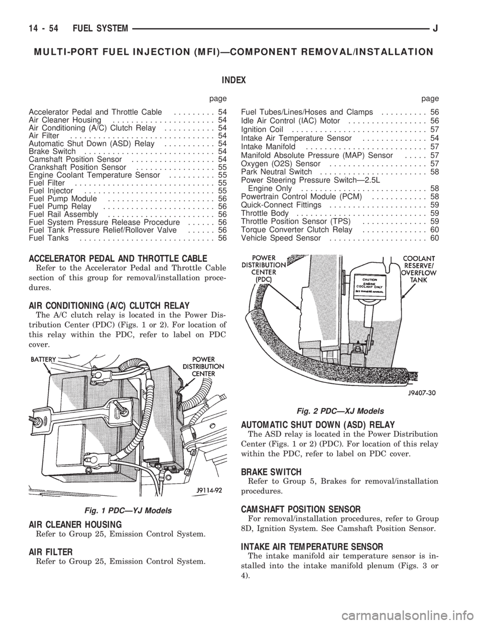
AIR CONDITIONING (A/C) CLUTCH RELAY
The A/C clutch relay is located in the Power Dis-
tribution Center (PDC) (Figs. 1 or 2). For location of
this relay within the PDC, refer to label on PDC
cover.
AIR CLEANER HOUSING
Refer to Group 25, Emission Control System.
AIR FILTER
Refer to Group 25, Emission Control System.
AUTOMATIC SHUT DOWN (ASD) RELAY
The ASD relay is located in the Power Distribution
Center (Figs. 1 or 2) (PDC). For location of this relay
within the PDC, refer to label on PDC cover.
BRAKE SWITCH
Refer to Group 5, Brakes for removal/installation
procedures.
CAMSHAFT POSITION SENSOR
For removal/installation procedures, refer to Group
8D, Ignition System. See Camshaft Position Sensor.
INTAKE AIR TEMPERATURE SENSOR
The intake manifold air temperature sensor is in-
stalled into the intake manifold plenum (Figs. 3 or
4).
Fig. 1 PDCÐYJ Models
Fig. 2 PDCÐXJ Models
14 - 54 FUEL SYSTEMJ