1994 JEEP CHEROKEE index
[x] Cancel search: indexPage 361 of 1784

INSTRUMENT PANEL AND GAUGESÐYJE
CONTENTS
page page
GAUGE PACKAGE DIAGNOSIS............ 22
GAUGE PACKAGE GENERAL INFORMATION . 22
GAUGE PACKAGE SERVICE PROCEDURES . . 24
INSTRUMENT CLUSTER DIAGNOSIS....... 14INSTRUMENT CLUSTER GENERAL INFORMATION.14
INSTRUMENT CLUSTER SERVICE PROCEDURES.. 17
SPECIFICATIONS....................... 27
INSTRUMENT CLUSTER GENERAL INFORMATION
SPEEDOMETER/ODOMETER SYSTEM
The speedometer/odometer system consists of an
electric speedometer and pushbutton reset odometer
mounted in the cluster. The system also includes the
wire harness from the cluster to the vehicle speed
sensor at the transmission, and the adapter and pin-
ion in the transmission. A signal is sent from a
transmission mounted vehicle speed sensor to the
speedometer/odometer circuitry through the wiring
harness. Refer to Group 21 - Transmission for select-
ing the proper pinion, and selecting and indexing the
proper adapter.
TACHOMETER
The tachometer displays the engine speed (RPM).
With the engine running, the tachometer receives anengine speed signal from the Powertrain Control
Module pin 43 (values shown in Specifications chart).
INDICATOR LAMPS
The Brake, Upshift (2.5L with 5 speed transmis-
sion except California), and Malfunction Indicator
(Check Engine) lamps are located in the indicator
lamp panel above the steering column. The lamps
share a common battery feed connection through the
ignition switch and fuse #9.
The turn signals, high beam indicator, seat belt re-
minder, hazard lamp, master lighting and illumina-
tion bulbs are supplied battery voltage through
various switches and share a common ground.
INSTRUMENT CLUSTER DIAGNOSIS
INDEX
page page
Brake Indicator Lamp...................... 16
DiagnosingÐAll Lamps Out................. 16
Instrument Panel Illumination Lamps.......... 16
Malfunction Indicator Lamp (Check Engine)..... 16Seat Belt Reminder Lamp................... 16
Speedometer............................ 14
Tachometer............................. 14
Upshift Indicator Lamp..................... 16
SPEEDOMETER
(1) Raise vehicle.
(2) Disconnect the vehicle speed sensor connector.
(3) Connect a voltmeter between the black wire
pin of the connector and ground.
(4) Turn the ignition switch to the ON position.
(5) Check for approximately 5 volts. If OK, per-
form vehicle speed sensor test. Refer to the appropri-
ate Powertrain Diagnostic Procedures manual. If not
OK, continue with step 6.
(6) Turn ignition switch to OFF position.(7) Check continuity between vehicle speed sensor
connector and terminal 13 of instrument cluster con-
nector. If OK, replace speedometer. If not OK, repair
open circuit.
TACHOMETER
(1) Tachometer input is from the Powertrain Con-
trol Module (PCM) pin 43. Use the DRB scan tool to
perform actuator test. If OK, continue with step 2. If
not, replace PCM.
(2) Check for continuity between cluster connector
pin 12 and PCM pin 43. If OK, replace tachometer. If
not, repair open circuit.
8E - 14 YJ INSTRUMENT PANEL AND GAUGESJ
Page 364 of 1784

INSTRUMENT CLUSTER SERVICE PROCEDURES
INDEX
page page
Headlamp Switch/Illumination Rheostat........ 21
Indicator Bezel Replacement................ 17
Instrument Cluster Bulb Replacement......... 19
Instrument Cluster Replacement............. 17Printed Circuit Replacement................ 19
Rear Defogger/Fog Lamp/Rear Wiper Switches . . 21
Speedometer Replacement................. 17
Tachometer Replacement.................. 17
INSTRUMENT CLUSTER REPLACEMENT
(1) Remove 6 shroud screws (Fig. 1).
(2) Slide shroud toward steering wheel.
(3) Remove 3 screws holding right side switch
panel (Fig. 2).
(4) Remove 3 screws holding left side switch bezel.(5) Remove 2 screws holding cluster in place.
(6) Lift up top of cluster. Roll cluster out between
steering column and instrument panel far enough to
reach connector located behind tachometer.
(7) Disconnect cluster connector and remove clus-
ter (Fig. 3).
(8) To install cluster, reverse the removal proce-
dures.
TACHOMETER REPLACEMENT
(1) Disconnect negative cable from battery.
(2) Remove instrumentation shroud (Fig. 1). Refer
to Instrument Cluster Replacement.
(3) Remove cluster as described in Instrument
Cluster replacement.
(4) Remove 3 screws and tachometer lens (Fig. 4).
(5) Gently pry up clip to release lens from bezel
(Fig. 5).
(6) Remove 3 screws from rear of housing (Fig. 6).
Remove tachometer.
(7) Install tachometer with 3 screws.
(8) Snap lens into place.
(9) Install lens with 3 screws.
(10) To install the cluster, reverse the removal pro-
cedures.
SPEEDOMETER REPLACEMENT
(1) Disconnect negative cable from battery.
(2) Remove instrument shroud (Fig. 1). Refer to In-
strument Cluster Replacement.
(3) Remove cluster as described in Instrument
Cluster Replacement.
(4) Remove 3 screws and speedometer lens (Fig. 7).
(5) Gently pry up clip to release lens from bezel
(Fig. 5).
(6) Remove 3 screws from rear of housing (Fig. 8).
Remove speedometer.
(7) Install speedometer with 3 screws.
(8) Snap lens into place.
(9) Install lens with 3 screws.
(10) To install the cluster, reverse the removal pro-
cedures.
INDICATOR BEZEL REPLACEMENT
(1) Disconnect negative cable from battery.
(2) Remove instrumentation shroud (Fig. 1).
(3) Remove 3 screws and tachometer lens (Fig. 4).
Fig. 2 Cluster Removal
Fig. 1 Instrument Shroud Removal/Installation
JYJ INSTRUMENT PANEL AND GAUGES 8E - 17
Page 383 of 1784
RADIO ANTENNA
INDEX
page page
Antenna Tests............................ 9
General Information........................ 8Replacement............................. 8
GENERAL INFORMATION
AM/FM radio model antennas must have a good
ground to eliminate static. The antenna mast is con-
nected to the inner wire of the coaxial cable and is
not grounded to any part of the vehicle. The coaxial
shield (the wire mesh) surrounding the center con-
ductor wire of the antenna lead-in cable is grounded
to the radio and the antenna base.
REPLACEMENT
XJ
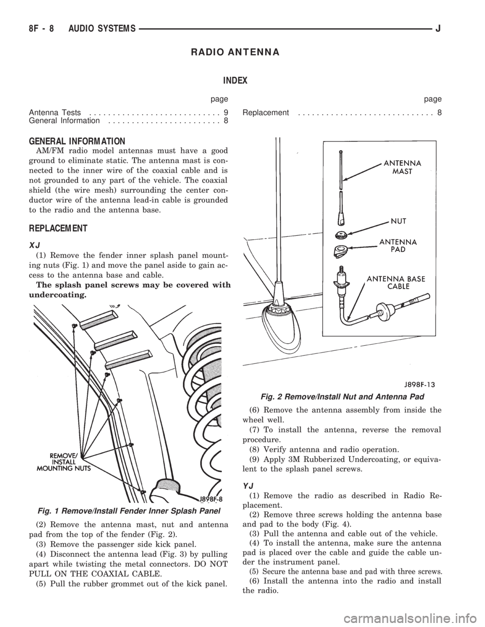
(1) Remove the fender inner splash panel mount-
ing nuts (Fig. 1) and move the panel aside to gain ac-
cess to the antenna base and cable.
The splash panel screws may be covered with
undercoating.
(2) Remove the antenna mast, nut and antenna
pad from the top of the fender (Fig. 2).
(3) Remove the passenger side kick panel.
(4) Disconnect the antenna lead (Fig. 3) by pulling
apart while twisting the metal connectors. DO NOT
PULL ON THE COAXIAL CABLE.
(5) Pull the rubber grommet out of the kick panel.(6) Remove the antenna assembly from inside the
wheel well.
(7) To install the antenna, reverse the removal
procedure.
(8) Verify antenna and radio operation.
(9) Apply 3M Rubberized Undercoating, or equiva-
lent to the splash panel screws.
YJ
(1) Remove the radio as described in Radio Re-
placement.
(2) Remove three screws holding the antenna base
and pad to the body (Fig. 4).
(3) Pull the antenna and cable out of the vehicle.
(4) To install the antenna, make sure the antenna
pad is placed over the cable and guide the cable un-
der the instrument panel.
(5) Secure the antenna base and pad with three screws.
(6) Install the antenna into the radio and install
the radio.
Fig. 1 Remove/Install Fender Inner Splash Panel
Fig. 2 Remove/Install Nut and Antenna Pad
8F - 8 AUDIO SYSTEMSJ
Page 394 of 1784
TEST PROCEDURES
INDEX
page page
Checking for Diagnostic Trouble Code......... 5
Electrical Tests at Powertrain Control Module.... 6
Electrical Tests at Servo.................... 5
Inoperative System........................ 5
Operational Check (Road Test)............... 7
Road Test............................... 5Speed Control Switch (Turn Signal Lever) Test . . . 7
Stop Lamp Speed Control Switch Test......... 7
Vacuum Supply Test....................... 7
Vehicle Speed Control System Electrical Tests . . . 5
Vehicle Speed Sensor Test.................. 5
ROAD TEST
Refer to Operational Check (Road Test) section to
verify reports of speed control system malfunction.
INOPERATIVE SYSTEM
Road test vehicle to verify reports of speed control
system malfunction. An inspection should be made
for loose electrical and vacuum connections at the
servo.
Check for correct installation of the vacuum check
valve in the hose from servo to vacuum source. The
word VAC on the valve must point toward the vac-
uum source.
Corrosion should be removed from electrical termi-
nals and a light coating of Mopar MultiPurpose
Grease, or equivalent, applied.
Inspection also should be made to verify that both
ends of the speed control cable are securely attached.
CHECKING FOR DIAGNOSTIC TROUBLE CODE
(1) When trying to verify a speed control system
electronic malfunction use a DRB scan tool to find
the cause (refer to Powertrain Diagnostic Procedures
manual).
If DRB is not available, the Diagnostic Trouble
Code (DTC) may be determined with the following
method:
(a) With key inserted in ignition switch, cycle
switch to ON position 3 times. On third cycle, leave
switch in ON position.
(b) After switch has been cycled 3 times, observe
Malfunction Indicator Lamp (CHECK ENGINE)
on instrument cluster. If a DTC is present, the code
will be displayed in a series of flashes representing
digits. Three flashes in rapid succession, a slight
pause, then 4 flashes in rapid succession would in-
dicate DTC 34.
(2) If a DTC 34 is observed, perform tests in the
sections Electrical Tests at Servo and Electrical Tests
at Powertrain Control Module.
If a DTC 15 is observed, perform test for a faulty
vehicle speed sensor.
(3) Correct any problems found when performing
these tests and recheck for DTC if changes were
made.
VEHICLE SPEED SENSOR TEST
For testing of the vehicle speed sensor and related
components, refer to Powertrain Diagnostic Proce-
dures manual.
VEHICLE SPEED CONTROL SYSTEM ELECTRICAL
TESTS
Vehicle speed control systems may be tested using
two different methods. One involves use of a DRB
scan tool. If this test method is desired, refer to Pow-
ertrain Diagnostic Procedures manual.
The other test method uses a voltmeter. The volt-
meter method is described in the following tests.
If any information is needed concerning wiring, re-
fer to Section 8W - Wiring Diagrams.
CAUTION: When test probing for voltage or conti-
nuity at electrical connectors, care must be taken
not to damage connector, terminals, or seals. If
these components are damaged, intermittent or
complete system failure may occur.
ELECTRICAL TESTS AT SERVO
(1) Turn ignition switch to the ON position. With
speed control switch in the ON position, setup a volt-
meter to read battery voltage and connect negative
lead to a good chassis ground.
(2) Disconnect 4-way connector going to servo
(Figs. 2 and 3). Blue wire with red tracer of main
harness 4-way connector should read approximately
battery voltage. If not, check for loose connections,
brake switch adjustment or, repair main harness as
necessary.
(3) Connect a jumper wire between male and fe-
male terminals of blue wire with red tracer. The
other 3 male terminals from servo should show bat-
tery voltage. If not, replace servo.
(4) Using an ohmmeter, connect one lead to a good
body ground. Touch other lead to black wire terminal
in 4-way connector of main harness. Meter should
show continuity. If not, repair ground circuit as nec-
essary.
JVEHICLE SPEED CONTROL SYSTEM 8H - 5
Page 398 of 1784
SERVICE PROCEDURES
INDEX
page page
Servo Cable Replacement................... 9
Speed Control Servo Replacement............ 9Speed Control Switch Replacement............ 9
SPEED CONTROL SERVO REPLACEMENT
REMOVAL
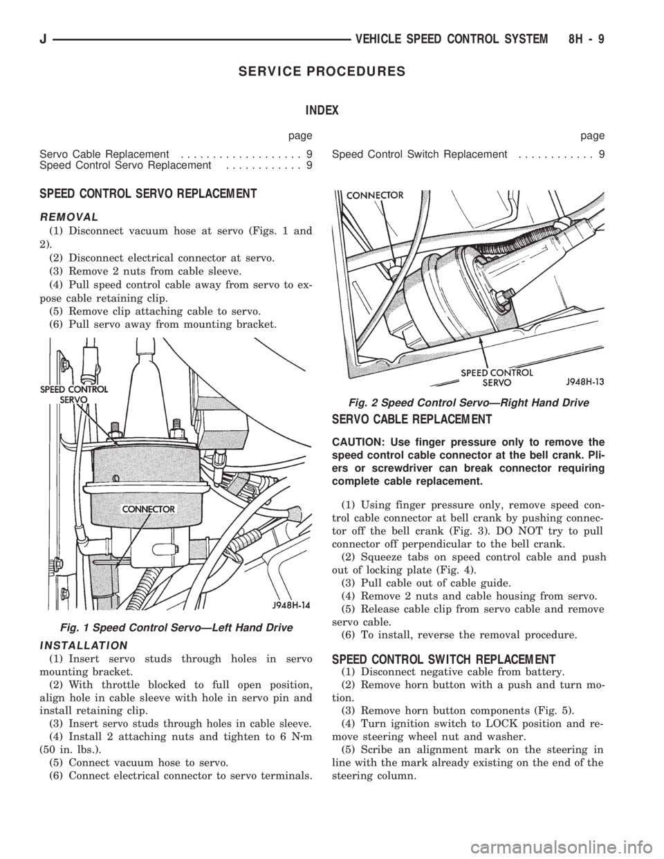
(1) Disconnect vacuum hose at servo (Figs. 1 and
2).
(2) Disconnect electrical connector at servo.
(3) Remove 2 nuts from cable sleeve.
(4) Pull speed control cable away from servo to ex-
pose cable retaining clip.
(5) Remove clip attaching cable to servo.
(6) Pull servo away from mounting bracket.
INSTALLATION
(1) Insert servo studs through holes in servo
mounting bracket.
(2) With throttle blocked to full open position,
align hole in cable sleeve with hole in servo pin and
install retaining clip.
(3)
Insert servo studs through holes in cable sleeve.
(4) Install 2 attaching nuts and tighten to 6 Nzm
(50 in. lbs.).
(5) Connect vacuum hose to servo.
(6) Connect electrical connector to servo terminals.
SERVO CABLE REPLACEMENT
CAUTION: Use finger pressure only to remove the
speed control cable connector at the bell crank. Pli-
ers or screwdriver can break connector requiring
complete cable replacement.
(1) Using finger pressure only, remove speed con-
trol cable connector at bell crank by pushing connec-
tor off the bell crank (Fig. 3). DO NOT try to pull
connector off perpendicular to the bell crank.
(2) Squeeze tabs on speed control cable and push
out of locking plate (Fig. 4).
(3) Pull cable out of cable guide.
(4) Remove 2 nuts and cable housing from servo.
(5) Release cable clip from servo cable and remove
servo cable.
(6) To install, reverse the removal procedure.
SPEED CONTROL SWITCH REPLACEMENT
(1) Disconnect negative cable from battery.
(2) Remove horn button with a push and turn mo-
tion.
(3) Remove horn button components (Fig. 5).
(4) Turn ignition switch to LOCK position and re-
move steering wheel nut and washer.
(5) Scribe an alignment mark on the steering in
line with the mark already existing on the end of the
steering column.
Fig. 2 Speed Control ServoÐRight Hand Drive
Fig. 1 Speed Control ServoÐLeft Hand Drive
JVEHICLE SPEED CONTROL SYSTEM 8H - 9
Page 408 of 1784
WINDSHIELD WIPERS
CONTENTS
page page
WIPER CONTROL SWITCH REPLACEMENT . . 15
WIPER SWITCH TESTING................ 19XJ .................................... 1
YJ .................................... 8
XJ
INDEX
page page
Diagnosing Rear Wiper..................... 6
Diagnosing Rear Wiper Washer.............. 6
Diagnosing Windshield Washer (Intermittent)..... 5
Diagnosing Windshield Washer (Non-Intermittent) . 4
Diagnosing Windshield Wipers............... 11
Front Wipers/Washers...................... 1
Intermittent Wiper Module................... 5
Liftgate Wiper............................ 5Liftgate Wiper Switch Replacement............ 6
Rear Wiper/Washer Switch Testing............ 7
Torque Specifications XJ.................... 7
Washer Pump Replacement................. 6
Washer Pump ReplacementÐLeft Hand Drive.... 2
Washer Pump ReplacementÐRight Hand Drive . . 3
Windshield Wiper Motor.................... 2
FRONT WIPERS/WASHERS
GENERAL
Two-speed electric windshield wipers and electric
washers are standard equipment. An optional inter-
mittent wiper system provides a pause between wipe
cycles for use during conditions of very light precipi-
tation.
The windshield wipers can be operated with the
windshield wiper switch only when the ignition
switch is in the ON or ACCESSORY position. A cir-
cuit breaker located in the fuse block protects the cir-
cuitry of the wiper system.
WIPERS
The standard windshield wiper circuit contains
three components; wiper/washer switch, motor, and
front washer pump. Both standard and intermittent
circuits are the same, except that the intermittent
circuit requires a module and delay resistance in the
wiper switch. Both circuits receive battery feed from,
and are protected by a 5.5 amp circuit breaker.
In the standard wiper circuit, the switch connects
the motor directly to battery feed for low and high
speed operation. In the intermittent circuit, the
switch supplies battery feed to the intermittent wiper
module, which then supplies the motor. In the delay
position, the module is connected with the variable
resistor in the wiper switch. The value of the resis-tance is used by the module to charge a capacitor,
which triggers the amount of delay between wipes.
The wiper motor has an arrangement of brushes
providing the two wiper speeds. When the wipers are
turned off, the park switch maintains current to the
motor until the wipers reach the park position on the
windshield.
The park arm in the motor assembly is connected
to the park switch and is driven by the motor. When
the wiper switch is turned off, current flows through
the contact and the module to the motor until the
wipers reach the park position.
CAUTION: The wiper arms and blades must not be
moved manually from side to side or damage may
result.
WASHERS
With the washer switch ON, current flows through
the washer pump to ground. The front washer pump
runs as long as the driver holds the switch ON. On
standard wipers, the washer switch automatically
moves the wiper switch to LO when the washer is
turned on. On intermittent wipers, the wiper module
runs the wiper motor on LO. Turning the switch to
OFF stops the wipers.
If the washer knob is depressed while the wiper
switch is in the OFF position, the wiper control will
operate for approximately 3 wipes and automatically
turn OFF.
JWINDSHIELD WIPERS 8K - 1
Page 415 of 1784
YJ
INDEX
page page
Diagnosing Windshield Wipers............... 11
Diagnosing Intermittent Windshield Washer..... 12
Diagnosing Non-Intermittent Windshield Washer . 12
Diagnosing Rear Wiper/Washer.............. 14
Front Wiper Arm and Pivot Assembly Replacement . 9
Front Wiper Arm Replacement............... 8
Front Wiper Blade Replacement.............. 8
Front Wiper Motor........................ 10Front Wipers/Washers General Information...... 8
Rear Washer Pump Replacement............ 13
Rear Wiper Arm Replacement............... 12
Rear Wiper Motor Replacement.............. 13
Rear Wiper Switch Replacement............. 13
Rear Wiper/Washer Switch Testing........... 14
Washer Nozzle Replacement................ 13
Washer Pump Replacement................ 11
FRONT WIPERS/WASHERS GENERAL
INFORMATION
The non-intermittent windshield wiper circuit con-
tains three components; control switch, motor and
washer pump. The intermittent circuit contains the
same components and a wiper module that provides
the delay function. Both circuits receive battery feed
from and are protected by a 5.3 amp circuit breaker.
In the non-intermittent wiper circuit, the switch
connects the motor directly to ignition feed for low
and high speed operation. In the intermittent circuit,
the switch supplies ignition feed to the delay module,
which then supplies the motor. In the delay position,
the module is connected with the variable resistor in
the wiper switch. The value of the resistance is used
by the solid state module to charge a capacitor,
which triggers the amount of delay between wipes.
The wiper motor has an arrangement of brushes
providing the two wiper speeds. When the wipers are
turned off, the park switch maintains current to the
motor until the wipers reach the park position on the
windshield.
The washer pump receives ignition feed either di-
rectly from the wiper switch or from the intermittent
module. In either case the electric motor will drive
the washer pump.
The wiper motor is mounted on the lower left cor-
ner of the windshield.
FRONT WIPER BLADE REPLACEMENT
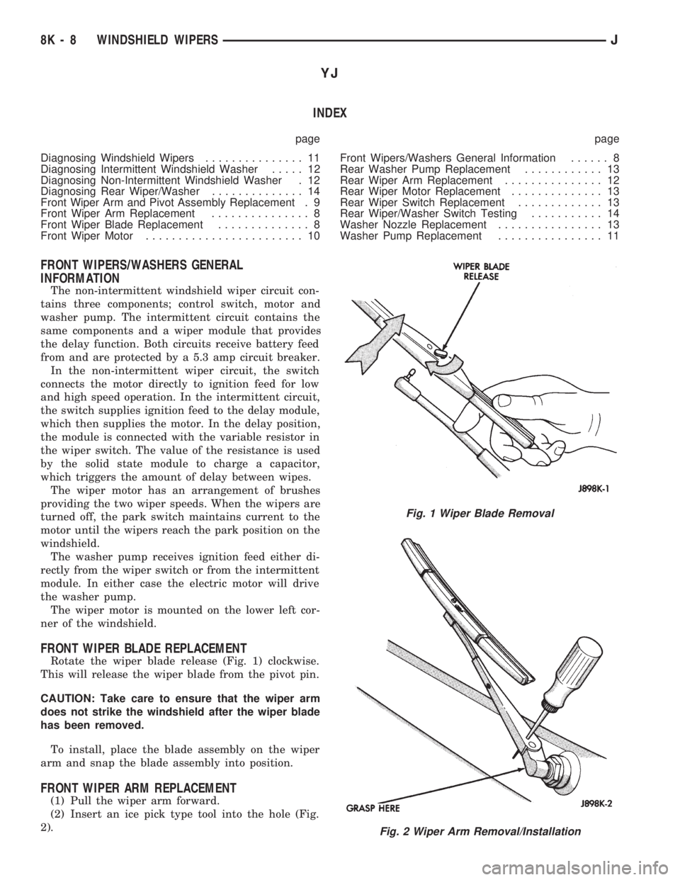
Rotate the wiper blade release (Fig. 1) clockwise.
This will release the wiper blade from the pivot pin.
CAUTION: Take care to ensure that the wiper arm
does not strike the windshield after the wiper blade
has been removed.
To install, place the blade assembly on the wiper
arm and snap the blade assembly into position.
FRONT WIPER ARM REPLACEMENT
(1) Pull the wiper arm forward.
(2) Insert an ice pick type tool into the hole (Fig.
2).
Fig. 1 Wiper Blade Removal
Fig. 2 Wiper Arm Removal/Installation
8K - 8 WINDSHIELD WIPERSJ
Page 428 of 1784
LAMPS
CONTENTS
page page
EXTERIOR LAMPS....................... 1
INTERIOR LAMPS...................... 19SPECIFICATIONS....................... 23
EXTERIOR LAMPS
INDEX
page page
Back-up/Rear Turn Signal/Tail Lamp Bulb
Replacement........................... 9
Center High Mounted Stop Lamp (CHMSL)ÐXJ . 10
Center High Mounted Stop Lamp (CHMSL)ÐYJ . 11
Daytime Running Lights (Canada Only)........ 16
DRL Module Replacement.................. 16
Fog Lamp Beam Adjustment................ 12
Fog Lamp Bulb/Element Replacement......... 13
Fog Lamp Replacement................... 15
Fog Lamp Service Information............... 12
Fog Lamp Switch Replacement.............. 14
Fog Lamp Trouble Diagnosis................ 12
Front Park/Turn Signal Lamp Bulb Replacement . . 8
Headlamp Beam Adjustment................. 3
Headlamp Bulb Replacement................ 3
Headlamp Delay Function Trouble DiagnosisÐXJ
Vehicles.............................. 16Headlamp Delay Module ReplacementÐXJ
Vehicles.............................. 16
Headlamp Dimmer Switch Replacement........ 6
Headlamp Switch Replacement............... 4
Headlamp Trouble DiagnosisÐXJ Vehicles...... 1
Headlamp Trouble DiagnosisÐYJ Vehicles...... 2
License Plate Lamp....................... 10
Sentinel Headlamp Delay ModuleÐXJ Vehicles . . 15
Service Information........................ 1
Side Marker Lamp Bulb Replacement.......... 7
Switch Tests............................. 2
Underhood Lamp Bulb Replacement.......... 18
Underhood Lamp Replacement.............. 18
Underhood Lamp Service Information......... 17
SERVICE INFORMATION
Exterior lamp circuits are comprised of the head-
lamp circuit, fog lamp circuit, and tail/side marker/
park lamp circuit. Battery voltage is controlled by
both the headlamp ON/OFF switch and headlamp
dimmer switch.
The dimmer switch functions as a fog lamp switch.
Voltage is applied to the fog lamp switch only when
the dimmer switch is in the low beam position.
HEADLAMP TROUBLE DIAGNOSISÐXJ VEHICLES
LOW AND HIGH BEAM INOPERATIVE BOTH
HEADLAMPS
(1) Place the headlamp switch in the ON position.
(2) Test the 40 amp fuse for continuity. If bad, re-
place fuse.
(3) Insert the test probe into terminal 5 of the
front lamp wire harness connector. Measure the re-
sistance from terminal 5 to body ground. The ohm-
meter should indicate zero ohms. If not OK, repair
the open circuit in the harness to body ground.(4) Disconnect the front lamp wire connector. Mea-
sure resistance between connector terminals 5 and 2.
Next measure between terminal 5 and 7. The ohm-
meter should indicate zero ohms for both measure-
ments. If not OK, replace the headlamp bulbs.
(5) Measure the voltage between the dimmer
switch wire connector terminal 2 and body ground.
The voltmeter should indicate battery voltage. If not
OK, continue with the next step.
The dimmer switch is integral with the turn
signal and is located on the steering column.
The dimmer switch switches the headlamp beam
when the turn signal lever is pulled rearward.
(6) Disconnect the dimmer switch wire connector
and place the headlamp switch in the OFF position.
Measure the resistance from terminal 2 to vehicle
body ground. The ohmmeter should indicate infinite
resistance. If OK, replace the headlamp switch and
continue with the next step. If not OK, repair the
short circuit in the wire harness that leads to termi-
nal 2.
JLAMPS 8L - 1