1994 JEEP CHEROKEE index
[x] Cancel search: indexPage 190 of 1784
ANTILOCK BRAKE SYSTEM OPERATION
INDEX
page page
ABS Operation in Antilock Braking Mode....... 43
ABS Operation in Normal Braking Mode....... 43
Acceleration Switch Operation............... 45
ECY Operation.......................... 46HCU Pump and Pedal Travel Sensor Operation . 44
HCU Solenoid Valve Operation.............. 43
System Power-Up and Initialization........... 43
Wheel Speed Sensor Operation............. 45
SYSTEM POWER-UP AND INITIALIZATION
The antilock system is in standby mode with the
ignition switch in Off or Accessory position. The an-
tilock electrical components are not operational.
Turning the ignition switch to On or Run position
allows battery voltage to flow through the switch to
the ECU ignition terminal.
The ABS system is activated when battery voltage
is supplied to the ECU. The ECU performs a system
initialization procedure at this point. Initialization
consists of a static and dynamic self check of system
electrical components.
The static check occurs immediately after the igni-
tion switch is turned to the On position. The dynamic
check occurs when vehicle road speed reaches ap-
proximately 10 kph (6 mph). During the dynamic
check, the ECU briefly cycles the pump to verify op-
eration. The HCU solenoids are checked continu-
ously.
If an ABS component exhibits a fault during ini-
tialization, the ECU illuminates the amber warning
light and registers a fault code in the microprocessor
memory.
ABS OPERATION IN NORMAL BRAKING MODE
The ECU monitors wheel speed sensor inputs con-
tinuously while the vehicle is in motion. However,
the ECU will not activate any ABS components as
long as sensor inputs and the acceleration switch in-
dicate normal braking.
During normal braking, the master cylinder, power
booster and wheel brake units all function as they
would in a vehicle without ABS. The HCU compo-
nents are not activated.
ABS OPERATION IN ANTILOCK BRAKING MODE
The purpose of the antilock system is to prevent
wheel lockup during periods of high wheel slip. Pre-
venting lockup helps maintain vehicle braking action
and steering control.
The antilock ECU activates the system whenever
sensor signals indicate periods of high wheel slip.
High wheel slip can be described as the point where
wheel rotation begins approaching zero (or lockup)
during braking. Periods of high wheel slip occur
when brake stops involve high pedal pressure and
rate of vehicle deceleration.The antilock system retards lockup during high
slip conditions by modulating fluid apply pressure to
the wheel brake units.
Brake fluid apply pressure is modulated according
to wheel speed, degree of slip and rate of decelera-
tion. A sensor at each wheel converts wheel speed
into electrical signals. These signals are transmitted
to the ECU for processing and determination of
wheel slip and deceleration rate.
The Jeep ABS system has three fluid pressure con-
trol channels. The front brakes are controlled sepa-
rately and the rear brakes in tandem (Fig. 10). A
speed sensor input signal indicating high slip condi-
tions activates the ECU antilock program.
Two solenoid valves are used in each antilock con-
trol channel (Fig. 11). The valves are all located
within the HCU valve body and work in pairs to ei-
ther increase, hold, or decrease apply pressure as
needed in the individual control channels.
The solenoid valves are not static during antilock
braking. They are cycled continuously to modulate
pressure. Solenoid cycle time in antilock mode can be
measured in milliseconds.
HCU SOLENOID VALVE OPERATION
Normal Braking
During normal braking, the HCU solenoid valves
and pump are not activated. The master cylinder and
power booster operate the same as a vehicle without
an ABS brake system.
Antilock Pressure Modulation
Solenoid valve pressure modulation occurs in three
stages which are: pressure increase, pressure hold,
and pressure decrease. The valves are all contained
in the valve body portion of the HCU.
Pressure Decrease
The outlet valve is opened and the inlet valve is
closed during the pressure decrease cycle (Fig. 11).
A pressure decrease cycle is initiated when speed
sensor signals indicate high wheel slip at one or
more wheels. At this point, the ECU opens the outlet
valve. Opening the outlet valve also opens the hy-
draulic return circuit to the master cylinder reser-
JANTILOCK BRAKE SYSTEM OPERATION 5 - 43
Page 194 of 1784
ABS COMPONENT SERVICE
INDEX
page page
Acceleration Sensor Installation.............. 52
Acceleration Sensor Removal............... 52
Combination Valve ReplacementÐXJ......... 55
Combination Valve ReplacementÐYJ......... 55
Component Serviceability................... 47
Correct Fluid Level....................... 48
ECU ReplacementÐXJ.................... 53
ECU ReplacementÐYJ.................... 53
Front Wheel Sensor Installation.............. 49
Front Wheel Sensor Removal............... 49
HCU InstallationÐXJ...................... 54
HCU InstallationÐYJ...................... 54HCU RemovalÐXJ....................... 53
HCU RemovalÐYJ....................... 54
Importance of Clean Brake Fluid............. 48
Master Cylinder Installation................. 50
Master Cylinder Removal.................. 50
Pedal Travel Sensor Service................ 51
Power Brake Booster Installation............. 51
Power Brake Booster Removal.............. 51
Rear Wheel Sensor Installation.............. 50
Rear Wheel Sensor Removal............... 49
Recommended Brake Fluid................. 48
Wheel Sensor Air Gap Adjustment........... 49
COMPONENT SERVICEABILITY
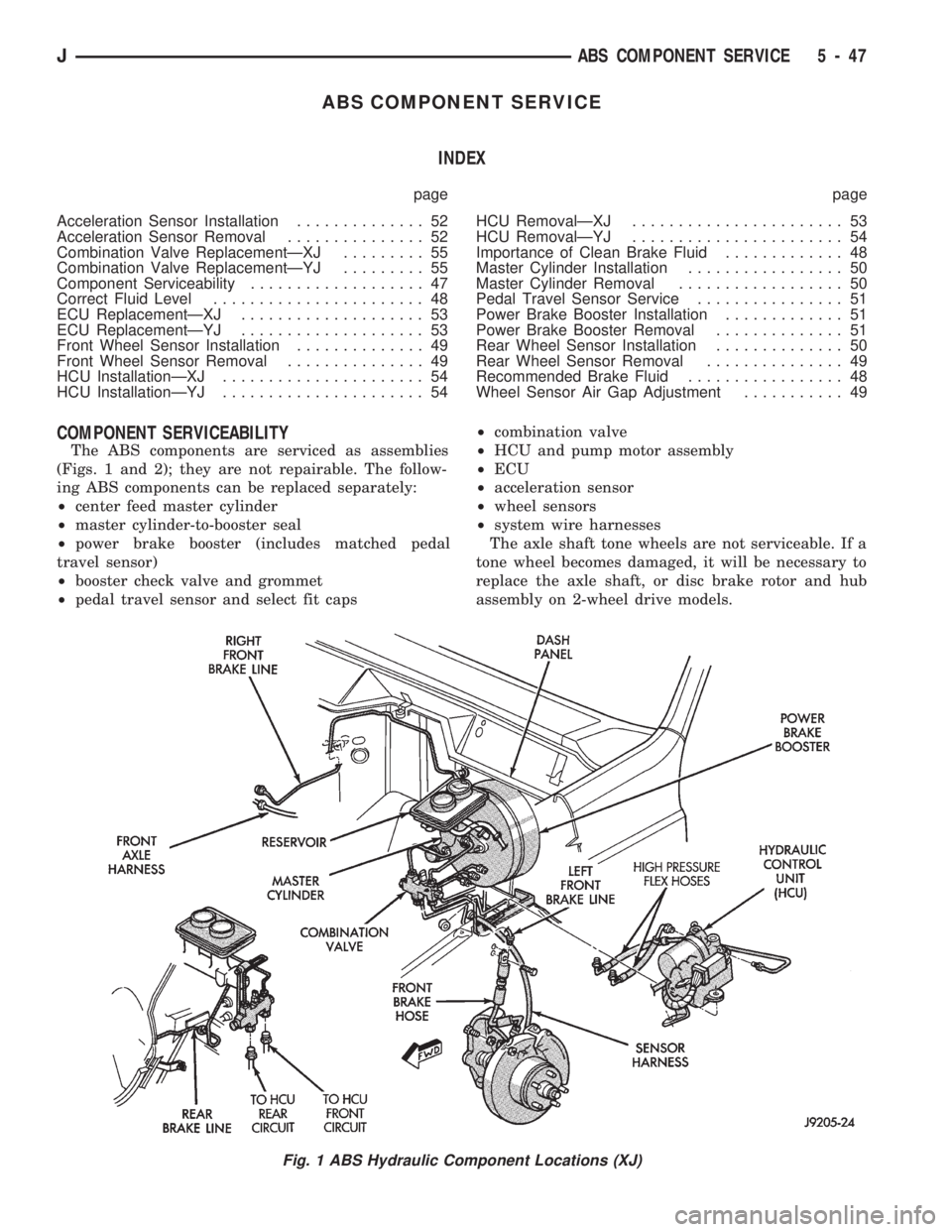
The ABS components are serviced as assemblies
(Figs. 1 and 2); they are not repairable. The follow-
ing ABS components can be replaced separately:
²center feed master cylinder
²master cylinder-to-booster seal
²power brake booster (includes matched pedal
travel sensor)
²booster check valve and grommet
²pedal travel sensor and select fit caps²combination valve
²HCU and pump motor assembly
²ECU
²acceleration sensor
²wheel sensors
²system wire harnesses
The axle shaft tone wheels are not serviceable. If a
tone wheel becomes damaged, it will be necessary to
replace the axle shaft, or disc brake rotor and hub
assembly on 2-wheel drive models.
Fig. 1 ABS Hydraulic Component Locations (XJ)
JABS COMPONENT SERVICE 5 - 47
Page 203 of 1784
PARKING BRAKES
INDEX
page page
General Service Information................ 56
Parking Brake Adjustment (XJ/YJ)............ 63
Parking Brake Cable Tensioner Replacement (XJ).61
Parking Brake Front Cable Replacement (YJ) . . . 62
Parking Brake Lever Installation
(XJ with Full Console)................... 60
Parking Brake Lever Installation
(XJ with Mini Console)................... 58
Parking Brake Lever Installation
(XJ Without Console).................... 60
Parking Brake Lever Removal
(XJ with Full Console).................... 59
Parking Brake Lever Removal
(XJ with Mini Console)................... 58
Parking Brake Lever Removal (XJ Without Console).60
Parking Brake Operation................... 56
Parking Brake Pedal Installation (YJ).......... 61
Parking Brake Pedal Removal (YJ)........... 61
Parking Brake Rear Cable Replacement (XJ) . . . 62
Parking Brake Rear Cable Replacement (YJ) . . . 63
GENERAL SERVICE INFORMATION
Parking brake adjustment is controlled by a
cable tensioner mechanism. The tensioner mech-
anism is used on 1991 through 1994 YJ models
and XJ models starting with 1992 models. The
cable tensioner, once adjusted at the factory,
will not need further adjustment under normal
circumstances. There are only two instances
when adjustment is required. The first is when a
new tensioner, or cables have been installed.
And the second, is when the tensioner and ca-
bles are disconnected for access to other brake
components.
PARKING BRAKE OPERATION
The rear brakes are utilized for the parking brake
function. They are actuated hydraulically during nor-
mal brake operation but are mechanically actuated
for parking brake operation.
Parking Brake Components
The rear brakeshoes are applied by a system of le-
vers and cables for parking brake operation. A foot
or hand operated lever in the passenger compartment
is the main application device. Actuating levers on
the secondary brakeshoes move the shoes directly
into contact with the drum braking surface. The ac-
tuating levers are interconnected by a system of ca-
bles and a tensioner mechanism. The tensioner
mechanism controls parking brake adjustment.
On XJ models, the cable tensioner is part of the le-
ver assembly. On YJ models, the tensioner and
equalizer are mounted in a bracket attached to the
underbody.
On YJ models, the parking brake front cable is at-
tached to the foot pedal at one end and the cable ten-
sioner at the other. The tensioner is connected to the
equalizer which is the connecting device for the rear
cables (Fig. 1).
On XJ models, the cable tensioner is connected di-rectly to the hand lever (a front cable is not used).
The tensioner rod is attached to the equalizer which
is the connecting point for the rear cables (Fig. 2).
The rear cables are connected to the actuating le-
ver on each secondary brakeshoe. The levers are at-
tached to the brakeshoes by a pin either pressed into,
or welded to the lever. A clip is used to secure the
pin in the brakeshoe. The pin allows each lever to
pivot independently of the brakeshoe.
Struts, installed between each brakeshoe, are used
to maintain shoe alignment and equal motion when
the parking brakes are applied. Each strut is
equipped with a combination tension and anti-rattle
spring.
Parking Brake Application
To apply the parking brakes, the foot pedal is
pressed downward, or the hand lever is pulled up-
ward, to an engaged position. This pulls the rear
brakeshoe actuating levers forward, by means of the
interconnected tensioner and cables.
As the actuating lever is pulled forward, the park-
ing brake strut (which is connected to both shoes),
exerts a linear force against the primary brakeshoe.
This action presses the primary shoe into contact
with the drum.
Once the primary shoe contacts the brake drum,
force exerted through the strut does not end. Instead,
further lever movement continues to exert force
against the strut; only this time, in a reverse direc-
tion. The strut force then causes the secondary shoe
to pivot into contact with the drum as well.
The brakeshoes will remain engaged with the
drum until the levers and cables are released. A gear
type ratcheting mechanism is used to hold the pedal
or lever in an applied position. Parking brake release
is accomplished by means of the release handle on
YJ models. Or by the hand lever release button on
XJ models.
5 - 56 PARKING BRAKESJ
Page 212 of 1784
BRAKE PEDAL AND BRAKELIGHT SWITCH
INDEX
page page
Brake Pedal Installation.................... 66
Brake Pedal Removal..................... 65
Brake Pedal Service...................... 65
Brakelight Switch Adjustment................ 66Brakelight Switch Installation................ 66
Brakelight Switch Removal................. 66
General Information....................... 65
GENERAL INFORMATION
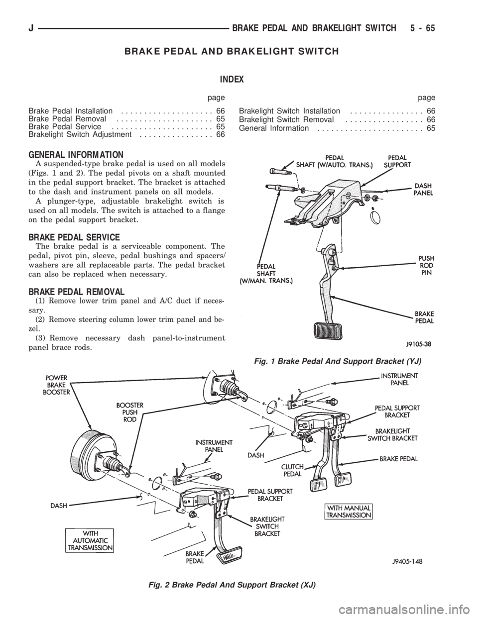
A suspended-type brake pedal is used on all models
(Figs. 1 and 2). The pedal pivots on a shaft mounted
in the pedal support bracket. The bracket is attached
to the dash and instrument panels on all models.
A plunger-type, adjustable brakelight switch is
used on all models. The switch is attached to a flange
on the pedal support bracket.
BRAKE PEDAL SERVICE
The brake pedal is a serviceable component. The
pedal, pivot pin, sleeve, pedal bushings and spacers/
washers are all replaceable parts. The pedal bracket
can also be replaced when necessary.
BRAKE PEDAL REMOVAL
(1) Remove lower trim panel and A/C duct if neces-
sary.
(2) Remove steering column lower trim panel and be-
zel.
(3) Remove necessary dash panel-to-instrument
panel brace rods.
Fig. 1 Brake Pedal And Support Bracket (YJ)
Fig. 2 Brake Pedal And Support Bracket (XJ)
JBRAKE PEDAL AND BRAKELIGHT SWITCH 5 - 65
Page 216 of 1784
CLUTCH
CONTENTS
page page
CLUTCH DIAGNOSIS..................... 3
CLUTCH SERVICE...................... 10GENERAL INFORMATION.................. 1
GENERAL INFORMATION
INDEX
page page
Clutch Component Lubrication................ 1
Clutch Components........................ 1Clutch Linkage Fluid....................... 1
Clutch Operation.......................... 2
CLUTCH COMPONENTS
MECHANICAL COMPONENTS
The clutch mechanism in XJ/YJ models with man-
ual transmission consists of a single, dry-type clutch
disc and a diaphragm style clutch cover. A hydraulic
linkage is used to operate the clutch disc and cover.
The transmission input shaft is supported in the
crankshaft by a bearing. A sleeve type release bear-
ing is used to engage and disengage the clutch cover
pressure plate.
The release bearing is operated by a release fork in
the clutch housing. The fork pivots on a ball stud
mounted inside the housing. The release fork is actu-
ated by a hydraulic slave cylinder mounted in the
housing. The slave cylinder is operated by a clutch
master cylinder mounted on the dash panel. The cyl-
inder push rod is connected to the clutch pedal.
The clutch disc has cushion springs in the disc hub.
The clutch disc facing is riveted to the hub. The fac-
ing is made from a non-asbestos material. The clutch
cover pressure plate is a diaphragm type with a one-
piece spring and multiple release fingers. The pres-
sure plate release fingers are preset during
manufacture and are not adjustable.
HYDRAULIC LINKAGE COMPONENTS
The hydraulic linkage consists of a clutch master
cylinder with integral reservoir, a clutch slave cylin-
der and an interconnecting fluid line.
The clutch master cylinder push rod is connected to
the clutch pedal. The slave cylinder push rod is con-
nected to the clutch release fork. The master cylinder
is mounted on the driver side of the dash panel ad-jacent to the brake master cylinder and booster as-
sembly. This positioning is similar for both left and
right hand drive models.
CLUTCH LINKAGE FLUID
The integral clutch master cylinder reservoir, slave
cylinder and fluid lines are prefilled with fluid prior
to assembly operations.
The hydraulic system should not require additional
fluid under normal circumstances. In fact,the reser-
voir fluid level will actually increase as normal
clutch wear occurs. For this reason, it is impor-
tant to avoid overfilling, or removing fluid from
the reservoir.
If inspection or diagnosis indicates additional fluid
may be needed, use Mopar brake fluid, or an equiv-
alent meeting standards SAE J1703 and DOT 3. Do
not use any other type of fluid.
CLUTCH COMPONENT LUBRICATION
Proper clutch component lubrication is important
to satisfactory operation. Using the correct lubricant
and not overlubricating are equally important. Apply
recommended lubricant sparingly to avoid disc and
pressure plate contamination.
Clutch and transmission components requiring lu-
brication are:
²pilot bearing
²release lever pivot ball stud
²release lever contact surfaces
²release bearing bore
²clutch disc hub splines
²clutch pedal pivot shaft bore
²clutch pedal bushings
²input shaft splines
JCLUTCH 6 - 1
Page 218 of 1784
CLUTCH DIAGNOSIS
INDEX
page page
Clutch Problem Causes..................... 3
General Diagnosis Information................ 3Inspection and Diagnosis Charts.............. 4
GENERAL DIAGNOSIS INFORMATION
Unless the cause of a clutch problem is obvious, ac-
curate problem diagnosis will usually require a road
test to confirm a problem. Component inspection will
then be required to determine the actual problem
cause.
During a road test, drive the vehicle at normal
speeds. Shift the transmission through all gear
ranges and observe clutch action. If chatter, grab,
slip, or improper release is experienced, remove and
inspect the clutch components. However, if the prob-
lem is noise or hard shifting, further diagnosis may
be needed as the transmission or another driveline
component may be at fault. Careful observation dur-
ing the test will help narrow the problem area.
CLUTCH PROBLEM CAUSES
CONTAMINATION
Fluid contamination is a frequent cause of clutch
malfunctions. Oil, water, or clutch fluid on the clutch
contact surfaces will cause faulty operation. The
usual result is chatter, slip and grab.
During inspection, note if any components are con-
taminated with oil, hydraulic fluid, or water/road
splash.
Oil contamination indicates a leak at either the
rear main seal or transmission input shaft. Oil leak-
age produces a residue of oil on the housing interior
and on the clutch cover and flywheel. Heat buildup
caused by slippage between the cover, disc and fly-
wheel, can sometimes bake the oil residue onto the
components. The glaze-like residue ranges in color
from amber to black.
Road splash contamination means dirt/water is en-
tering the clutch housing due to loose bolts, housing
cracks, or through hydraulic line openings. Driving
through deep water puddles can force water/road
splash into the housing through such openings.
Clutch fluid leaks are from loose or damaged slave
cylinder fluid lines and connecting fittings. However,
clutch fluid leaks will usually be noted and corrected
before severe contamination occurs.
CLUTCH MISALIGNMENT
Clutch components must be in proper alignment
with the crankshaft and transmission input shaft.Misalignment caused by excessive runout or warpage
of any clutch component will cause grab, chatter and
improper clutch release.
Flywheel Runout
Check flywheel runout whenever misalignment is
suspected. Flywheel runout should not exceed 0.08
mm (0.003 in.). Measure runout at the outer edge of
the flywheel face with a dial indicator. Mount the in-
dicator on a stud installed in place of one of the fly-
wheel bolts.
Common causes of runout are:
²heat warpage
²improper machining
²incorrect bolt tightening
²improper seating on crankshaft flange shoulder
²foreign material on crankshaft flange
Flywheel machining is not recommended. The fly-
wheel clutch surface is machined to a unique contour
and machining will negate this feature. However,
minor flywheel scoring can be cleaned up by hand
with 180 grit emery, or with surface grinding equip-
ment. Remove only enough material to reduce scor-
ing (approximately 0.001 - 0.003 in.). Heavy stock
removal isnot recommended.Replace the flywheel
if scoring is severe and deeper than 0.076 mm (0.003
in.). Excessive stock removal can result in flywheel
cracking or warpage after installation; it can also
weaken the flywheel and interfere with proper clutch
release.
Clean the crankshaft flange before mounting the
flywheel. Dirt and grease on the flange surface may
cock the flywheel causing excessive runout. Use new
bolts when remounting a flywheel and secure the
bolts with Mopar Lock And Seal. Tighten flywheel
bolts to specified torque only. Overtightening can dis-
tort the flywheel hub causing runout.
Clutch Cover And Disc Runout
Check the clutch disc before installation. Axial
(face) runout of anewdisc should not exceed 0.50
mm (0.020 in.). Measure runout about 6 mm (1/4 in.)
from the outer edge of the disc facing. Obtain an-
other disc if runout is excessive.
Check condition of the clutch before installation. A
warped cover or diaphragm spring will cause grab
and incomplete release or engagement. Be careful
JCLUTCH DIAGNOSIS 6 - 3
Page 225 of 1784
CLUTCH SERVICE
INDEX
page page
Clutch Cover and Disc Installation............ 10
Clutch Cover and Disc Removal............. 10
Clutch Fluid Level........................ 14
Clutch Housing Replacement................ 11
Clutch Hydraulic Linkage Installation.......... 12
Clutch Hydraulic Linkage Removal........... 11Clutch Pedal Installation................... 15
Clutch Pedal Removal..................... 15
Clutch Safety Precautions.................. 10
Flywheel Service......................... 15
Pilot Bearing Replacement................. 11
Release Bearing Replacement............... 11
CLUTCH SAFETY PRECAUTIONS
WARNING: EXERCISE CARE WHEN SERVICING
CLUTCH COMPONENTS. DUST AND DIRT ON
CLUTCH PARTS USE MAY CONTAIN ASBESTOS FI-
BERS. BREATHING EXCESSIVE CONCENTRATIONS
OF THESE FIBERS CAN CAUSE SERIOUS BODILY
HARM. WEAR A RESPIRATOR DURING SERVICE
AND NEVER CLEAN CLUTCH COMPONENTS WITH
COMPRESSED AIR OR WITH A DRY BRUSH. EI-
THER CLEAN THE COMPONENTS WITH A WATER
DAMPENED RAGS OR USE A VACUUM CLEANER
SPECIFICALLY DESIGNED FOR REMOVING ASBES-
TOS FIBERS AND DUST. DO NOT CREATE DUST
BY SANDING A CLUTCH DISC. REPLACE THE DISC
IF THE FRICTION MATERIAL IS DAMAGED OR
CONTAMINATED. DISPOSE OF ALL DUST AND
DIRT CONTAINING ASBESTOS FIBERS IN SEALED
BAGS OR CONTAINERS. THIS WILL HELP MINIMIZE
EXPOSURE TO YOURSELF AND TO OTHERS. FOL-
LOW ALL RECOMMENDED SAFETY PRACTICES
PRESCRIBED BY THE OCCUPATIONAL SAFETY
AND HEALTH ADMINISTRATION (OSHA) AND THE
ENVIRONMENTAL SAFETY AGENCY (EPA), FOR
THE HANDLING AND DISPOSAL OF PRODUCTS
CONTAINING ASBESTOS.
CLUTCH COVER AND DISC REMOVAL
(1) Remove transmission. Refer to procedures in
Group 21.
(2) If original clutch cover will be reinstalled,
mark position of cover on flywheel for assembly ref-
erence. Use paint or a scriber for this purpose.
(3) If clutch cover is to be replaced, cover bolts can
be removed in any sequence. However, if original
cover will be reinstalled, loosen cover bolts evenly
and in rotation to relieve spring tension equally.
This is necessary avoid warping cover.
(4) Remove cover bolts and remove cover and disc
(Fig. 2).
CLUTCH COVER AND DISC INSTALLATION
(1) Lightly scuff sand flywheel face with 180 grit
emery cloth. Then clean surface with a wax and
grease remover.
(2) Lubricate pilot bearing with Mopar high tem-
perature bearing grease.
(3) Check runout and free operation of new clutch
disc as follows:
(a) Slide disc onto transmission input shaft
splines. Disc should slide freely on splines.
(b) Leave disc on shaft and check face runout
with dial indicator. Check runout at disc hub and
about 6 mm (1/4 in.) from outer edge of facing.
(c) Face runout should not exceed 0.5 mm (0.020
in.). Obtain another clutch disc if runout exceeds
this limit.
(4) Position clutch disc on flywheel. Be sure side of
disc marked flywheel side is positioned against fly-
wheel (Fig. 2). If disc is not marked, be sure flat side
of disc hub is toward flywheel.
(5) Insert clutch alignment tool in clutch disc (Fig.
3).
(6) Insert alignment tool in pilot bearing and posi-
tion disc on flywheel. Be sure disc hub is positioned
correctly. Side of hub marked Flywheel Side should
face flywheel (Fig. 2). If disc is not marked, place flat
side of disc against flywheel.
(7) Position clutch cover over disc and on flywheel
(Fig. 3).
(8) Install clutch cover bolts finger tight.
(9) Tighten cover bolts evenly and in rotation a
few threads at a time.Cover bolts must be tight-
ened evenly and to specified torque to avoid dis-
torting cover. Tightening torques are 31 Nzm (23
ft. lbs.) on 2.5L engines and 54 Nzm (40 ft. lbs.) on
4.0L engines.
(10) Apply light coat of Mopar high temperature
bearing grease to pilot bearing hub and splines of
transmission input shaft.Do not overlubricate
shaft splines. This will result in grease contami-
nation of disc.
(11) Install transmission (Fig. 4). Refer to proce-
dures in Group 21.
6 - 10 CLUTCH SERVICEJ
Page 237 of 1784
DIAGNOSIS
INDEX
page page
DRB Scan Tool........................... 5
On-Board Diagnostics (OBD)................. 4Preliminary Checks........................ 5
ON-BOARD DIAGNOSTICS (OBD)
FOR COOLING SYSTEM COMPONENTS
The powertrain control module (PCM) has been
programmed to monitor the certain following cooling
system components:
²If the engine has remained cool for too long a pe-
riod, such as with a stuck open thermostat, a Diag-
nostic Trouble Code (DTC) number 17 can be
observed at the Check Engine Lamp.
²If an open or shorted condition has developed in
the relay circuit controlling the electric radiator fan,
a Diagnostic Trouble Code (DTC) number 35 can be
observed at the Check Engine Lamp.
If the problem is sensed in a monitored circuit of-
ten enough to indicate an actual problem, a DTC is
stored. The DTC will be stored in the PCM memory
for eventual display to the service technician. If the
problem is repaired or ceases to exist, the PCM can-
cels the DTC after 51 engine starts.
Certain criteria must be met for a DTC to be en-
tered into PCM memory. The criteria may be a spe-
cific range of engine rpm, engine temperature and/or
input voltage to the PCM.
A DTC indicates that the PCM has recognized an
abnormal signal in a circuit or the system. A DTC
may indicate the result of a failure, but never iden-
tify the failed component directly.
It is possible that a DTC for a monitored circuit
may not be entered into memory even though a mal-
function has occurred. Refer to On-Board Diagnostics
(OBD) in Group 14, Fuel Systems for additional in-
formation.
ACCESSING DIAGNOSTIC TROUBLE CODES
A stored Diagnostic Trouble Code (DTC) can be dis-
played by cycling the ignition key On-Off-On-Off-On
within three seconds and observing the Malfunction
Indicator Lamp. This lamp was formerly referred to
as the Check Engine Lamp. The lamp is located on
the instrument panel.
They can also be displayed through the use of the
Diagnostic Readout Box (DRB) scan tool. The DRB
connects to the data link connector in the engine
compartment (Figs. 5 or 6). For operation of the
DRB, refer to the appropriate Powertrain Diagnostic
Procedures service manual.EXAMPLES:
²If the lamp flashes 1 time, pauses and flashes 7
more times, a flashing Diagnostic Trouble Code
(DTC) number 17 is indicated.
²If the lamp flashes 3 times, pauses and flashes 5
more times, a flashing Diagnostic Trouble Code
(DTC) number 35 is indicated.
After any stored DTC information has been ob-
served, the display will end with a flashing DTC
number 55. This will indicate the end of all stored
information.
Fig. 5 Data Link ConnectorÐYJ ModelsÐTypical
Fig. 6 Data Link ConnectorÐXJ ModelsÐTypical
7 - 4 COOLING SYSTEMJ