1994 JEEP CHEROKEE index
[x] Cancel search: indexPage 242 of 1784
SERVICE PROCEDURES
INDEX
page page
Coolant................................ 15
Coolant Reserve/Overflow System............ 19
Cooling System Cleaning/Reverse Flushing..... 17
Cooling System Fans..................... 26
Cooling System Hoses.................... 26
Draining Cooling System................... 16
Radiator Pressure Cap.................... 20
Radiators............................... 22Refilling Cooling System................... 17
Testing Cooling System for Leaks............ 18
Thermostat............................. 13
Transmission Oil Coolers................... 29
Water Pump Tests........................ 9
Water PumpsÐGeneral Information............ 9
Water PumpsÐRemoval/Installation........... 10
WATER PUMPSÐGENERAL INFORMATION
A centrifugal water pump circulates coolant
through the water jackets, passages, intake manifold,
radiator core, cooling system hoses and heater core.
The pump is driven from the engine crankshaft by a
drive belt on all engines.
The water pump impeller is pressed onto the rear
of a shaft that rotates in bearings pressed into the
housing. The housing has a small hole to allow seep-
age to escape. The water pump seals are lubricated
by the antifreeze in the coolant mixture. No addi-
tional lubrication is necessary.
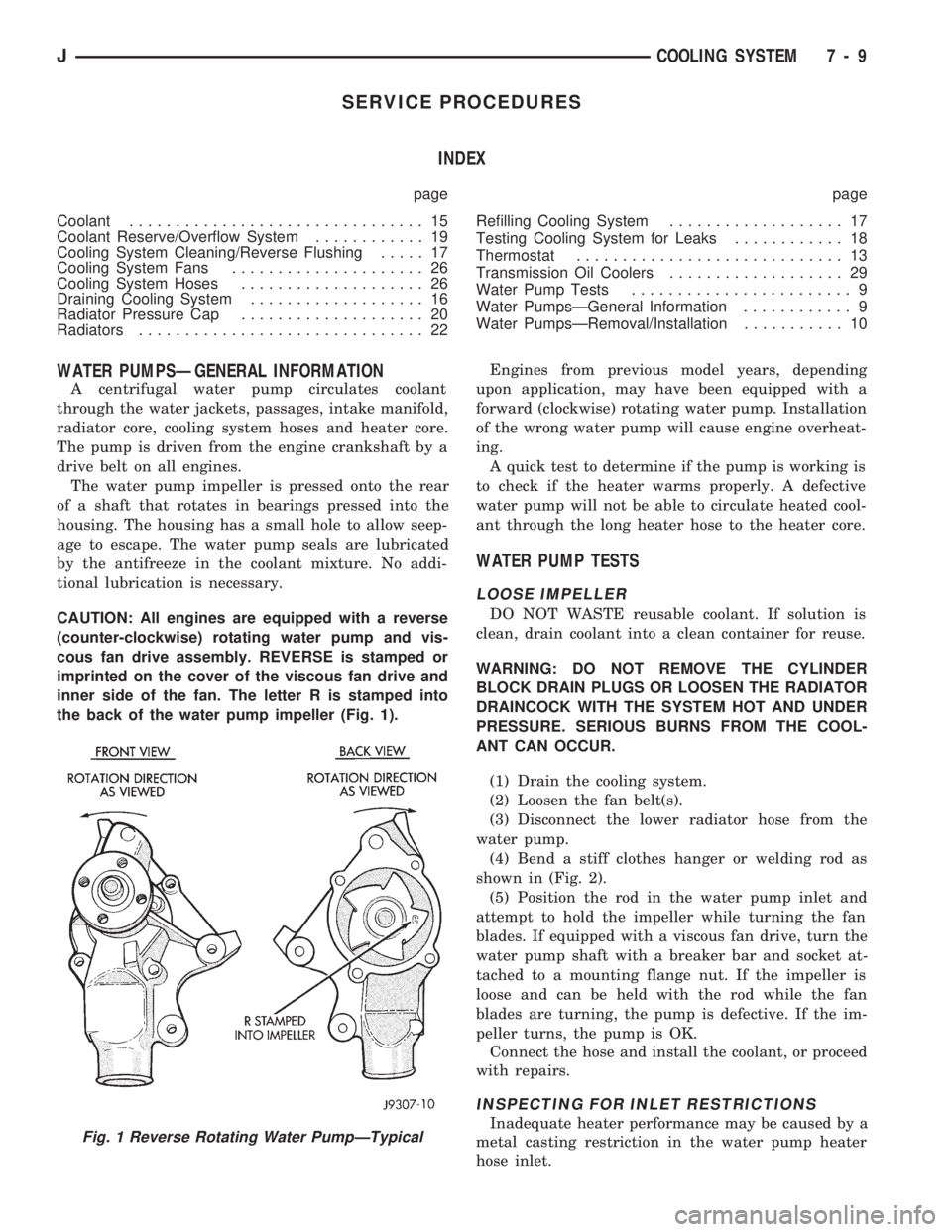
CAUTION: All engines are equipped with a reverse
(counter-clockwise) rotating water pump and vis-
cous fan drive assembly. REVERSE is stamped or
imprinted on the cover of the viscous fan drive and
inner side of the fan. The letter R is stamped into
the back of the water pump impeller (Fig. 1).Engines from previous model years, depending
upon application, may have been equipped with a
forward (clockwise) rotating water pump. Installation
of the wrong water pump will cause engine overheat-
ing.
A quick test to determine if the pump is working is
to check if the heater warms properly. A defective
water pump will not be able to circulate heated cool-
ant through the long heater hose to the heater core.
WATER PUMP TESTS
LOOSE IMPELLER
DO NOT WASTE reusable coolant. If solution is
clean, drain coolant into a clean container for reuse.
WARNING: DO NOT REMOVE THE CYLINDER
BLOCK DRAIN PLUGS OR LOOSEN THE RADIATOR
DRAINCOCK WITH THE SYSTEM HOT AND UNDER
PRESSURE. SERIOUS BURNS FROM THE COOL-
ANT CAN OCCUR.
(1) Drain the cooling system.
(2) Loosen the fan belt(s).
(3) Disconnect the lower radiator hose from the
water pump.
(4) Bend a stiff clothes hanger or welding rod as
shown in (Fig. 2).
(5) Position the rod in the water pump inlet and
attempt to hold the impeller while turning the fan
blades. If equipped with a viscous fan drive, turn the
water pump shaft with a breaker bar and socket at-
tached to a mounting flange nut. If the impeller is
loose and can be held with the rod while the fan
blades are turning, the pump is defective. If the im-
peller turns, the pump is OK.
Connect the hose and install the coolant, or proceed
with repairs.
INSPECTING FOR INLET RESTRICTIONS
Inadequate heater performance may be caused by a
metal casting restriction in the water pump heater
hose inlet.Fig. 1 Reverse Rotating Water PumpÐTypical
JCOOLING SYSTEM 7 - 9
Page 264 of 1784
ENGINE ACCESSORY DRIVE BELTS
INDEX
page page
Automatic Belt TensionerÐXJ Models......... 36
Belt Diagnosis........................... 31
Belt Schematics......................... 34
Belt ServiceÐExcept Right Hand Drive........ 34
Belt ServiceÐWith Right Hand Drive.......... 35Belt Tension Specifications................. 34
Belt TensionÐExcept Right Hand Drive (RHD) . . 33
Belt TensionÐRight Hand Drive (RHD)........ 34
General Information....................... 31
GENERAL INFORMATION
CAUTION: When installing a serpentine accessory
drive belt, the belt MUST be routed correctly. If not,
the engine may overheat due to water pump rotat-
ing in wrong direction. Refer to the appropriate en-
gine Belt Schematic in this group for the correct
belt routing. Or, refer to the Belt Routing Label lo-
cated in the engine compartment.
BELT DIAGNOSIS
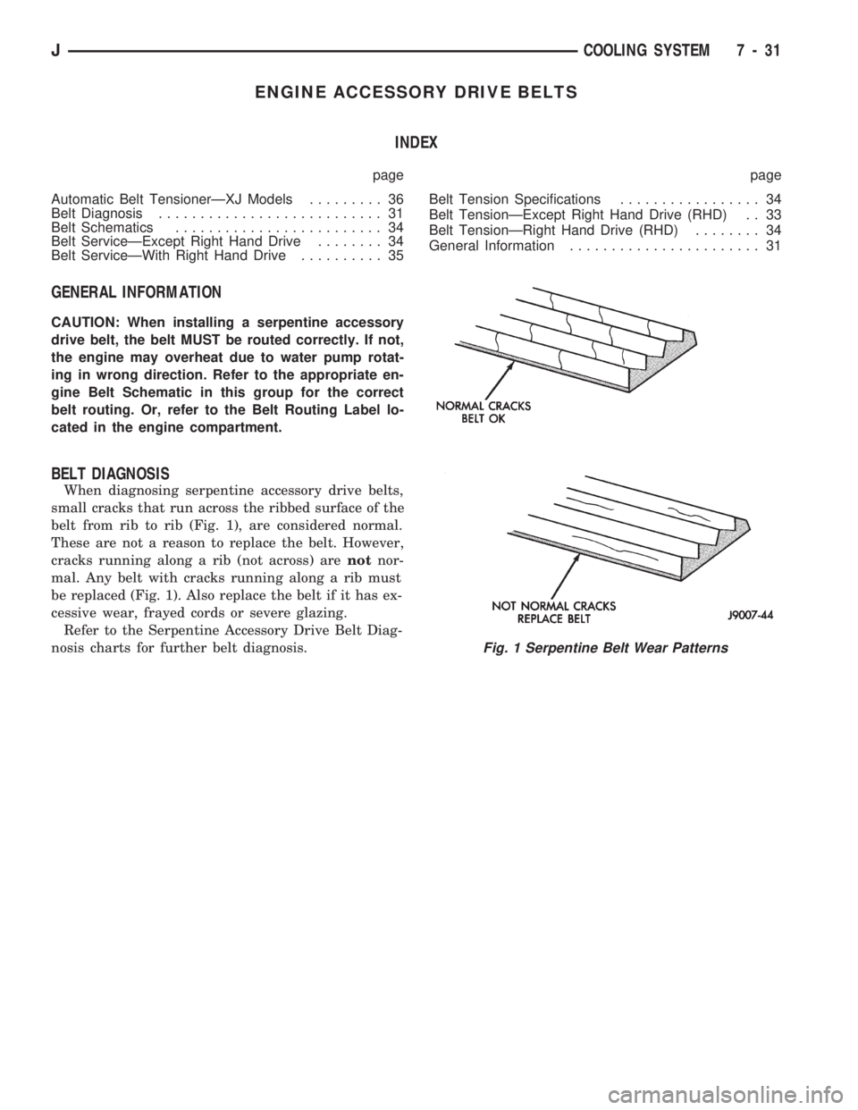
When diagnosing serpentine accessory drive belts,
small cracks that run across the ribbed surface of the
belt from rib to rib (Fig. 1), are considered normal.
These are not a reason to replace the belt. However,
cracks running along a rib (not across) arenotnor-
mal. Any belt with cracks running along a rib must
be replaced (Fig. 1). Also replace the belt if it has ex-
cessive wear, frayed cords or severe glazing.
Refer to the Serpentine Accessory Drive Belt Diag-
nosis charts for further belt diagnosis.
Fig. 1 Serpentine Belt Wear Patterns
JCOOLING SYSTEM 7 - 31
Page 274 of 1784
ELECTRICAL
GROUP INDEX
Group Group
AUDIO SYSTEMS....................... 8F
BATTERY/STARTER/GENERATOR SERVICE . . 8B
BATTERY/STARTING/CHARGING SYSTEMS
DIAGNOSTICS........................ 8A
CHIME/WARNING BUZZER SYSTEM....... 8U
HORNS............................... 8G
IGNITION SYSTEMS.................... 8D
INSTRUMENT PANEL AND GAUGES........ 8E
LAMPS............................... 8L
OVERHEAD CONSOLE................... 8CPOWER LOCKS........................ 8P
POWER MIRRORS...................... 8T
POWER SEAT.......................... 8R
POWER WINDOWS..................... 8S
REAR WINDOW DEFOGGER.............. 8N
TURN SIGNALS AND HAZARD WARNING
FLASHERS........................... 8J
VEHICLE SPEED CONTROL SYSTEM....... 8H
WINDSHIELD WIPERS AND WASHERS..... 8K
WIRING DIAGRAMS.................... 8W
BATTERY/STARTING/CHARGING SYSTEMS DIAGNOSTICS
CONTENTS
page page
BATTERY TEST PROCEDURES............. 2
ENGINE STARTER MOTOR TEST
PROCEDURES ON VEHICLE.............. 9GENERATOR TEST PROCEDURES ON
VEHICLE............................. 14
IGNITION OFF DRAW (IOD) DIAGNOSIS...... 8
USING ON-BOARD DIAGNOSTIC SYSTEM.... 19
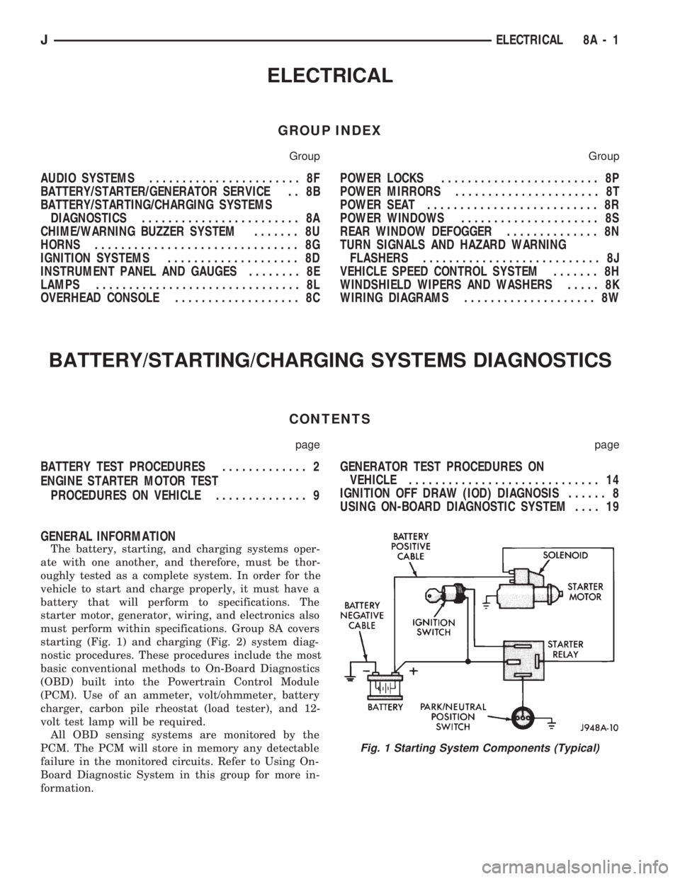
GENERAL INFORMATION
The battery, starting, and charging systems oper-
ate with one another, and therefore, must be thor-
oughly tested as a complete system. In order for the
vehicle to start and charge properly, it must have a
battery that will perform to specifications. The
starter motor, generator, wiring, and electronics also
must perform within specifications. Group 8A covers
starting (Fig. 1) and charging (Fig. 2) system diag-
nostic procedures. These procedures include the most
basic conventional methods to On-Board Diagnostics
(OBD) built into the Powertrain Control Module
(PCM). Use of an ammeter, volt/ohmmeter, battery
charger, carbon pile rheostat (load tester), and 12-
volt test lamp will be required.
All OBD sensing systems are monitored by the
PCM. The PCM will store in memory any detectable
failure in the monitored circuits. Refer to Using On-
Board Diagnostic System in this group for more in-
formation.
Fig. 1 Starting System Components (Typical)
JELECTRICAL 8A - 1
Page 275 of 1784
BATTERY TEST PROCEDURES
INDEX
page page
Battery Charging.......................... 5
Battery Diagnostics Chart................... 7
Battery Load Test......................... 4
Battery Open Circuit Voltage Test............. 3Battery Testing General Information........... 3
General Information........................ 2
Hydrometer Test.......................... 3
Specifications............................ 8
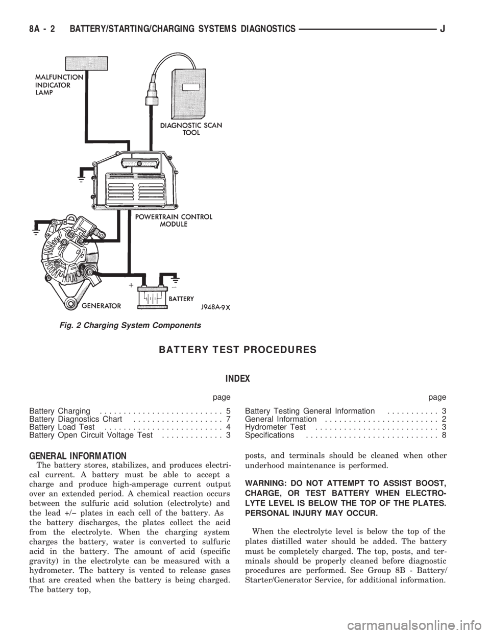
GENERAL INFORMATION
The battery stores, stabilizes, and produces electri-
cal current. A battery must be able to accept a
charge and produce high-amperage current output
over an extended period. A chemical reaction occurs
between the sulfuric acid solution (electrolyte) and
the lead +/þ plates in each cell of the battery. As
the battery discharges, the plates collect the acid
from the electrolyte. When the charging system
charges the battery, water is converted to sulfuric
acid in the battery. The amount of acid (specific
gravity) in the electrolyte can be measured with a
hydrometer. The battery is vented to release gases
that are created when the battery is being charged.
The battery top,posts, and terminals should be cleaned when other
underhood maintenance is performed.
WARNING: DO NOT ATTEMPT TO ASSIST BOOST,
CHARGE, OR TEST BATTERY WHEN ELECTRO-
LYTE LEVEL IS BELOW THE TOP OF THE PLATES.
PERSONAL INJURY MAY OCCUR.
When the electrolyte level is below the top of the
plates distilled water should be added. The battery
must be completely charged. The top, posts, and ter-
minals should be properly cleaned before diagnostic
procedures are performed. See Group 8B - Battery/
Starter/Generator Service, for additional information.
Fig. 2 Charging System Components
8A - 2 BATTERY/STARTING/CHARGING SYSTEMS DIAGNOSTICSJ
Page 282 of 1784
ENGINE STARTER MOTOR TEST PROCEDURES ON VEHICLE
INDEX
page page
2.5L Starter Motor Noise Diagnosis........... 13
General Information........................ 9
Starter Control Circuit Tests................ 11
Starter Feed Circuit Tests - (Voltage Drop Method).9
Starter System Diagnostic Inspections.......... 9
Starting System Cold Cranking Test........... 9
GENERAL INFORMATION
The starting system consists of an:
²ignition switch
²starter relay
²park/neutral position switch (automatic transmis-
sion)
²wiring harness
²battery
²starter motor with an integral solenoid.
These components form 2 separate circuits. A high
amperage circuit that feeds the starter motor up to
300+ amps, and a control circuit that operates on
less than 20 amps.
STARTER SYSTEM DIAGNOSTIC INSPECTIONS
Before removing any unit from the starter motor
system for repair, perform the following inspections:
BATTERY INSPECTION
To determine condition of the battery, perform the
testing procedure outlined in Battery Test Proce-
dures.
WIRING INSPECTION
Inspect wiring for damage. Inspect all connections
at the starter motor solenoid, park/neutral position
switch (if equipped), back-up lamp switch connector,
ignition switch, starter relay, and battery (including
all ground connections). Clean and tighten all con-
nections as required.
SOLENOID, RELAY AND IGNITION SWITCH
INSPECTION
Inspect the solenoid, relay and switch to determine
their condition. Also, if equipped with automatic
transmission, inspect condition of the park/neutral
position switch. Testing information can be found in
the following pages.
STARTING SYSTEM COLD CRANKING TEST
(1) Battery must first pass load and voltage drop
tests and be fully charged before proceeding. Refer to
Battery Test Procedures.(2) Connect a suitable volt-ampere tester to the
battery terminals (Fig. 1). Refer to the operating in-
structions provided with the tester being used.
(3) Fully engage parking brake, place manual
transmission in NEUTRAL, automatic transmission
in PARK.
(4) Verify that all lamps and accessories are OFF.
(5) Remove coil secondary cable from distributor
and connect to ground.
(6) Rotate and hold the ignition switch in the
START position. Note cranking voltage and amper-
age.
(a) If voltage reads above 9.6 volts and amperage
draw reads above specifications, go to Starter Feed
Circuit Tests.
(b) If voltage reads 12.5 volts or greater and am-
perage reads below specifications, go to Starter
Control Circuit Tests.
A cold engine will increase starter motor cur-
rent and reduce battery voltage.
STARTER FEED CIRCUIT TESTS - (VOLTAGE DROP
METHOD)
The voltage drop tests will determine if there is ex-
cessive resistance in the high current circuit. When
performing these tests, it is important that the volt-
meter be connected to the terminals that the cables
are connected to, instead of to the cables themselves.
For example, when testing between the battery and
solenoid, touch the voltmeter test probes to the bat-
tery post and the solenoid threaded stud. The follow-
ing operation will require a voltmeter, accurate to
1/10 of a volt.
Before performing the tests, assure the following
procedures are accomplished:
²remove coil secondary cable from distributor and
connect to ground
²transmission in NEUTRAL (manual transmission)
or PARK (automatic transmission)
²parking brake applied
²battery is fully charged (refer to Battery Test Pro-
cedures).
JBATTERY/STARTING/CHARGING SYSTEMS DIAGNOSTICS 8A - 9
Page 287 of 1784
GENERATOR TEST PROCEDURES ON VEHICLE
INDEX
page page
Diagnostic Procedures..................... 15
General Information....................... 14Operational Check with Battery Indicator
(Base Cluster Only)..................... 14
Operational Check with Voltmeter............ 15
GENERAL INFORMATION
The generator is belt-driven by the engine. All en-
gines use serpentine drive.
The amount of DC current produced by the gener-
ator is controlled by the Powertrain Control Module
(PCM) (Fig. 1).
All vehicles are equipped with On-Board Diagnos-
tics (OBD). All OBD sensing systems are monitored
by the PCM. The PCM will store in electronic mem-
ory any detectable failure within the monitored cir-
cuits. Refer to Using On-Board Diagnostic System in
this group for more information.
OPERATIONAL CHECK WITH BATTERY INDICATOR
(BASE CLUSTER ONLY)
When operating normally, the indicator bulb will
come on when the ignition switch is turned to the
ON or START position. After the engine starts, the
indicator bulb goes off. With the engine running, the
charge indicator should come on only when there is a
problem in the charging system (base cluster only).
Fig. 10 Starter Motor Shimming
Fig. 1 Charging System Components (Typical)
8A - 14 BATTERY/STARTING/CHARGING SYSTEMS DIAGNOSTICSJ
Page 297 of 1784

ENGINE STARTER MOTOR SERVICE PROCEDURES
INDEX
page page
2.5L Starter General Information.............. 4
2.5L Starter Motor Removal/Installation......... 5
4.0L Starter General Information.............. 6
4.0L Starter Motor Removal/Installation......... 6General Information........................ 4
Park/Neutral Position Switch................. 6
Starter Relay Replacement.................. 4
GENERAL INFORMATION
This section will cover the starting system compo-
nent service procedures only. For diagnostic proce-
dures, refer to Group 8A - Battery/Starting/Charging
Systems Diagnostics.
Starting system components: battery, starter mo-
tor, starter relay, starter solenoid, ignition switch,
connecting wires and battery cables. A park/neutral
position switch is used with automatic transmissions.
STARTER RELAY REPLACEMENT
The starter relay is located in the Power Distribu-
tion Center (Figs. 1 and 2). Refer to underside of
Power Distribution Center cover for relay location.
(1) Disconnect negative cable from battery.
(2) Replace relay.
(3) Connect negative cable to battery.
(4) Test relay operation.
2.5L STARTER GENERAL INFORMATION
The 2.5L engine starter motor incorporates several
features to create an efficient, lightweight unit.
A planetary gear system (intermediate transmis-
sion) between the electric motor and pinion shaftmakes it possible to reduce the dimensions of the
starter. This also makes it possible to obtain a higher
rotational speed to produce the same torque at the
pinion.
The permanent magnet field consists of six two-
component high strength magnets. The magnets are
aligned according to their polarity and are perma-
nently fixed in the starter frame.
The brush holder plate consists of a plastic base-
plate with four tubular brush holders.
This unit is highly sensitive to hammering, shocks
and external pressure.
CAUTION: The starter motor MUST NOT BE
CLAMPED in a vise by the starter frame. Doing so
may damage the magnets. It may be clamped by the
mounting flange ONLY.
CAUTION: Do not connect starter motor incorrectly
when tests are being performed. The magnets may
be damaged and rendered unserviceable.
²Ensure cleanliness when performing repairs.
Fig. 1 Power Distribution CenterÐXJ
Fig. 2 Power Distribution CenterÐYJ
8B - 4 BATTERY/STARTER/GENERATOR SERVICEJ
Page 314 of 1784

IGNITION SYSTEMS
CONTENTS
page page
COMPONENT IDENTIFICATION/SYSTEM
OPERATION.......................... 1
COMPONENT REMOVAL/INSTALLATION..... 20DIAGNOSTICS/SERVICE PROCEDURES....... 8
IGNITION SWITCH...................... 30
SPECIFICATIONS....................... 33
COMPONENT IDENTIFICATION/SYSTEM OPERATION
INDEX
page page
Automatic Shut Down (ASD) Relay............ 1
Camshaft Position Sensor................... 1
Crankshaft Position Sensor.................. 2
Distributors.............................. 3
Engine Coolant Temperature Sensor........... 4
General Information........................ 1Ignition Coil.............................. 4
Intake Manifold Air Temperature Sensor........ 5
Manifold Absolute Pressure (MAP) Sensor...... 5
Powertrain Control Module (PCM)............. 6
Throttle Position Sensor.................... 6
GENERAL INFORMATION
Throughout this group, references are made to par-
ticular vehicle models by alphabetical designation
(XJ or YJ) or by the particular vehicle nameplate. A
chart showing a breakdown of alphabetical designa-
tions is included in the Introduction group at the be-
ginning of this manual.
This section of the group, Component Identifica-
tion/System Operation, will discuss ignition system
operation and will identify ignition system compo-
nents.
For diagnostic procedures and adjustments, refer to
the Diagnostics/Service Procedures section of this
group.
For removal and installation of ignition system
components, refer to the Component Removal/Instal-
lation section of this group.
For other useful information, refer to On-Board Di-
agnostics in the General Diagnosis sections of Group
14, Fuel System in this manual.
For operation of the DRB Scan Tool, refer to the
appropriate Powertrain Diagnostic Procedures ser-
vice manual.
An Ignition specifications section is included at the
end of this group. A general Maintenance Schedule
(mileage intervals) for ignition related items can be
found in Group 0, Lubrication and Maintenance. This
schedule can also be found in the Owners Manual.
IGNITION SYSTEMS
A multi-port, fuel injected engine is used on all
models. The ignition system is controlled by the Pow-
ertrain Control Module (PCM) on all engines. The
PCM was formerly referred to as the SBEC or engine
controller.
The ignition system consists of:
²Spark Plugs
²Ignition Coil
²Secondary Ignition Cables
²Ignition distributor (contains rotor and camshaft
position sensor)
²Powertrain Control Module (PCM)
²Crankshaft Position Sensor
AUTOMATIC SHUT DOWN (ASD) RELAY
The automatic shut down (ASD) relay is located in
the Power Distribution Center (PDC) near the bat-
tery (Fig. 1 or 2). As one of its functions, it will sup-
ply battery voltage to the ignition coil. The ground
circuit for the ASD relay is controlled by the Power-
train Control Module (PCM). The PCM regulates
ASD relay operation by switching the ground circuit
on-and-off.
CAMSHAFT POSITION SENSOR
The camshaft position sensor is located in the igni-
tion distributor (Figs. 3 or 4) on all engines.
The camshaft position sensor contains a hall effect
device called a sync signal generator to generate a
fuel sync signal. This sync signal generator detects a
JIGNITION SYSTEMS 8D - 1