1994 JEEP CHEROKEE index
[x] Cancel search: indexPage 1539 of 1784
UNDERBODY COMPONENTS
INDEX
page page
Catalytic Converter/Muffler/Tailpipe Support
Brackets............................. 85
Front Skid Plate......................... 84
Fuel and Brake Fluid Tube Retainer Clip....... 86
Fuel Filler Hose Splash ShieldÐXJ Vehicles.... 86
Fuel Filter Bracket........................ 86Fuel Tank Skid Plate...................... 84
Fuel Tank Support Strap................... 86
Rear Tow HookÐXJ Vehicles............... 87
Service Information....................... 84
Trailer Hitches........................... 88
Transfer Case Skid Plate.................. 84
SERVICE INFORMATION
In some cases, components in the following proce-
dures either support, or are concealed by other com-
ponents. When necessary, refer to component
removal procedure for service access.
FRONT SKID PLATE
REMOVAL
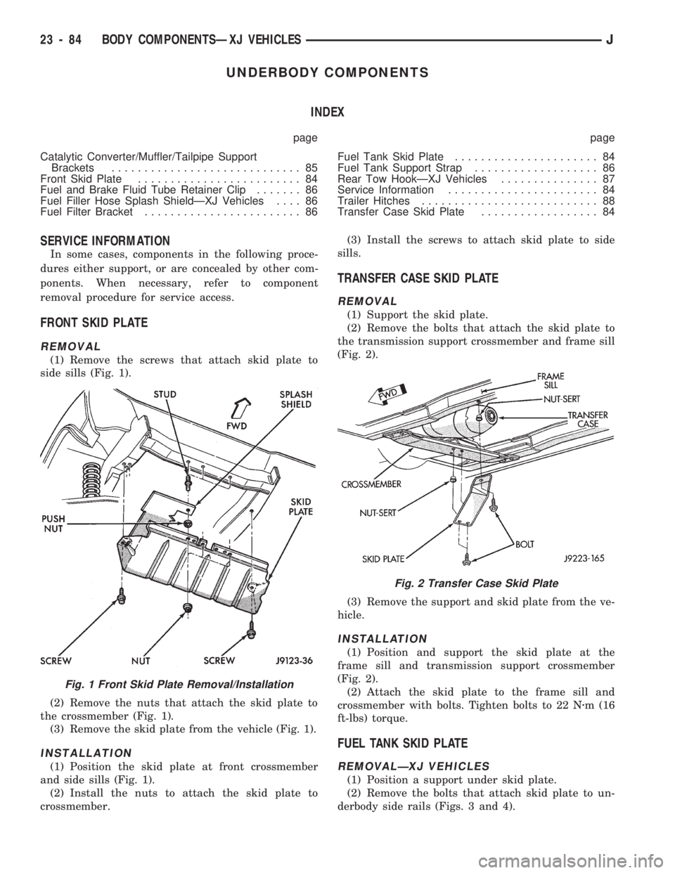
(1) Remove the screws that attach skid plate to
side sills (Fig. 1).
(2) Remove the nuts that attach the skid plate to
the crossmember (Fig. 1).
(3) Remove the skid plate from the vehicle (Fig. 1).
INSTALLATION
(1) Position the skid plate at front crossmember
and side sills (Fig. 1).
(2) Install the nuts to attach the skid plate to
crossmember.(3) Install the screws to attach skid plate to side
sills.
TRANSFER CASE SKID PLATE
REMOVAL
(1) Support the skid plate.
(2) Remove the bolts that attach the skid plate to
the transmission support crossmember and frame sill
(Fig. 2).
(3) Remove the support and skid plate from the ve-
hicle.
INSTALLATION
(1) Position and support the skid plate at the
frame sill and transmission support crossmember
(Fig. 2).
(2) Attach the skid plate to the frame sill and
crossmember with bolts. Tighten bolts to 22 Nzm (16
ft-lbs) torque.
FUEL TANK SKID PLATE
REMOVALÐXJ VEHICLES
(1) Position a support under skid plate.
(2) Remove the bolts that attach skid plate to un-
derbody side rails (Figs. 3 and 4).
Fig. 1 Front Skid Plate Removal/Installation
Fig. 2 Transfer Case Skid Plate
23 - 84 BODY COMPONENTSÐXJ VEHICLESJ
Page 1546 of 1784
INTERIOR COMPONENTS
INDEX
page page
Assist HandleÐXJ Vehicles................ 118
B/C-Pillar and Liftgate Pillar Trim CoversÐ
XJ Vehicles.......................... 116
Bucket Seat Cushion and Cover............. 98
Bucket Seat Platform and Tracks........... 105
Bucket Seatback Cover and Frame.......... 100
Bucket Seatback Reconditioning............ 102
Carpets and Floor Mats................... 129
Dash Panel Insulation Panel................ 95
Front Bucket Seats....................... 97
Front Carpet/MatÐXJ Vehicles............. 129
Front Inner Scuff Plate/Cowl Side Trim PanelÐ
XJ Vehicles.......................... 114
Front Shoulder Belt/BuckleÐXJ Vehicles...... 119
Full Floor ConsoleÐXJ Vehicles............ 125
Headliner.............................. 121
I/P Ash Receiver Tray Lamp................ 92
I/P Tweeter Speaker/Courtesy Lamp Support
Bracket.............................. 95
Instrument Cluster Bezel................... 91
Instrument Cluster/Switch/Lighter/Radio/Hevac . . . 91
Instrument Panel......................... 93
Interior Trim Panels and Scuff PlatesÐXJ Vehicles. 112
Jack StorageÐXJ Vehicles................ 127
Mini-Floor ConsoleÐXJ Vehicles............ 124
Outer Scuff PlatesÐXJ Vehicles............ 118
Power Bucket Seat Components............ 106
Quarter and Wheelhouse Trim PanelsÐ
XJ Vehicles.......................... 115
Quarter Trim Panel ExtensionÐXJ Vehicles . . . 115
Rear Carpet/MatÐXJ Vehicles.............. 130
Rear Seat Cushion CoverÐXJ Vehicles...... 107
Rear Seat Cushion ReconditioningÐXJ Vehicles . 108
Rear Seat CushionÐXJ Vehicles............ 107
Rear Seatback CoverÐXJ Vehicles.......... 111
Rear Seatback Latch Striker and BumperÐ
XJ Vehicles.......................... 111
Rear Seatback ReconditioningÐXJ Vehicles . . . 111
Rear SeatbackÐXJ Vehicles............... 109
Rear Shoulder/Lap Belt/BuckleÐXJ Vehicles . . . 120
Spare Tire/Wheel Holddown and Floor BracketsÐ
XJ Vehicles.......................... 128
Sunvisors............................. 124
Windshield Side MouldingÐXJ Vehicles...... 114
INSTRUMENT CLUSTER BEZEL
REMOVAL
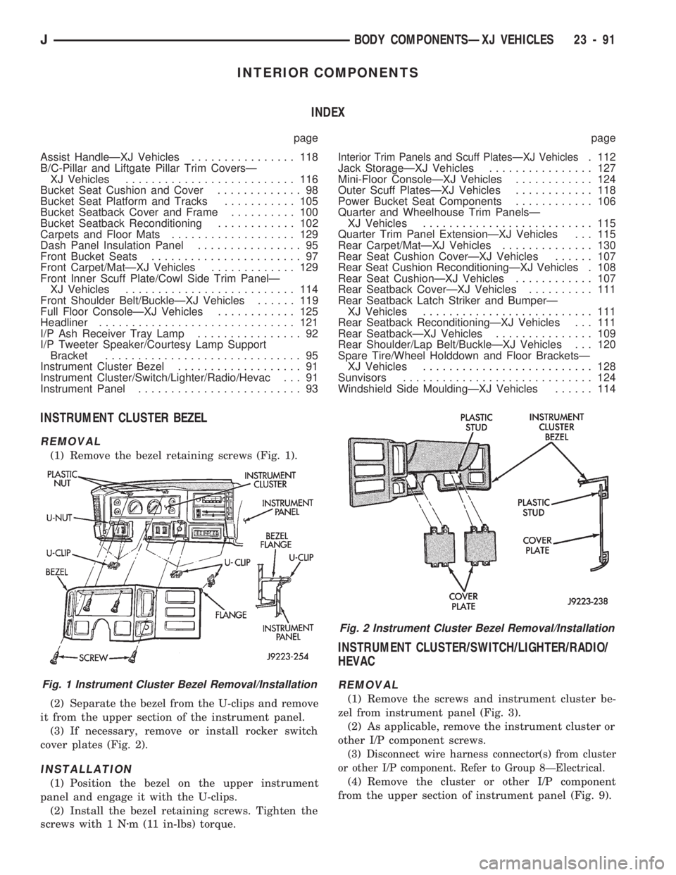
(1) Remove the bezel retaining screws (Fig. 1).
(2) Separate the bezel from the U-clips and remove
it from the upper section of the instrument panel.
(3) If necessary, remove or install rocker switch
cover plates (Fig. 2).
INSTALLATION
(1) Position the bezel on the upper instrument
panel and engage it with the U-clips.
(2) Install the bezel retaining screws. Tighten the
screws with 1 Nzm (11 in-lbs) torque.
INSTRUMENT CLUSTER/SWITCH/LIGHTER/RADIO/
HEVAC
REMOVAL
(1) Remove the screws and instrument cluster be-
zel from instrument panel (Fig. 3).
(2) As applicable, remove the instrument cluster or
other I/P component screws.
(3) Disconnect wire harness connector(s) from cluster
or other I/P component. Refer to Group 8ÐElectrical.
(4) Remove the cluster or other I/P component
from the upper section of instrument panel (Fig. 9).
Fig. 1 Instrument Cluster Bezel Removal/Installation
Fig. 2 Instrument Cluster Bezel Removal/Installation
JBODY COMPONENTSÐXJ VEHICLES 23 - 91
Page 1589 of 1784
EXTERIOR COMPONENTS
INDEX
page page
Battery Tray........................... 140
Body Extension Panels and FasciasÐYJ
Renegade Vehicles..................... 147
Body Side Step Moulding................. 145
Body Stripes/Decals..................... 153
Cowl Grille and Screen................... 139
Cowl Weatherstrip Seal................... 139
Exterior Nameplates (Adhesive-Backed)....... 158
External Spare/Wheel Tire Carrier........... 172
Fender Flare........................... 144
Fender Inner Splash Shields............... 147
Fender Splash Aprons.................... 147
Fenders............................... 141
Fog LampÐYJ Renegade Vehicles.......... 150
Front Fascia and Skid PlateÐYJ Renegade
Vehicles............................. 148
Front Fender Extension PanelÐYJ Renegade
Vehicles............................. 149
Fuel Filler Protector/Nozzle................ 158
Half Metal Door Mirror (External)............ 158
Hard Top Liftgate Glass.................. 162
Hard Top Repair........................ 165
Hard Top Roof Vent..................... 165
Hard Top Service....................... 164
Hard Top Service Information.............. 164Hood................................. 137
Hood Alignment......................... 138
Hood Insulator Panel..................... 138
Hood Safety Latch....................... 139
Liftgate Glass Weatherstrip Seal Replacement . . 163
Radiator Grille Applique................... 134
Rear Fascia and Skid PlateÐYJ Renegade
Vehicles............................. 152
Rear Quarter Extension PanelÐYJ Renegade
Vehicles............................. 151
Rocker Extension PanelÐYJ Renegade
Vehicles............................. 150
Soft Top Service........................ 167
Soft Top Service Information............... 166
Sport Bar............................. 171
Tailgate Adjustment...................... 160
Tailgate Hinge.......................... 159
Tailgate Latch and Release Handle.......... 160
Tailgate Latch Striker..................... 161
Tailgate Lock Cylinder.................... 160
Tailgate Service......................... 159
Tailgate Service Information................ 159
Tailgate Weatherstrip Seal................. 161
Wheelhouse Splash Liners................ 146
RADIATOR GRILLE APPLIQUE
REMOVAL
(1) Raise the hood.
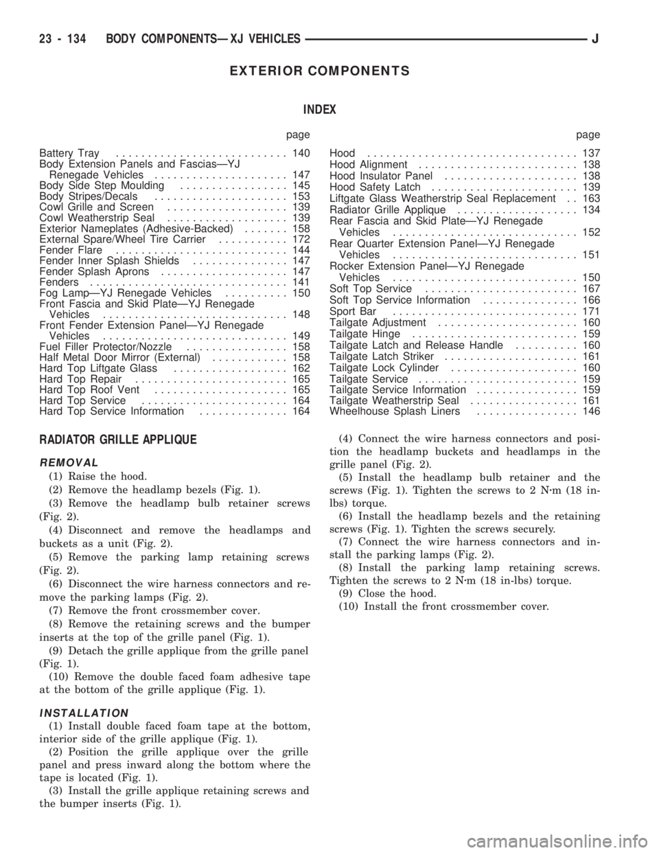
(2) Remove the headlamp bezels (Fig. 1).
(3) Remove the headlamp bulb retainer screws
(Fig. 2).
(4) Disconnect and remove the headlamps and
buckets as a unit (Fig. 2).
(5) Remove the parking lamp retaining screws
(Fig. 2).
(6) Disconnect the wire harness connectors and re-
move the parking lamps (Fig. 2).
(7) Remove the front crossmember cover.
(8) Remove the retaining screws and the bumper
inserts at the top of the grille panel (Fig. 1).
(9) Detach the grille applique from the grille panel
(Fig. 1).
(10) Remove the double faced foam adhesive tape
at the bottom of the grille applique (Fig. 1).
INSTALLATION
(1) Install double faced foam tape at the bottom,
interior side of the grille applique (Fig. 1).
(2) Position the grille applique over the grille
panel and press inward along the bottom where the
tape is located (Fig. 1).
(3) Install the grille applique retaining screws and
the bumper inserts (Fig. 1).(4) Connect the wire harness connectors and posi-
tion the headlamp buckets and headlamps in the
grille panel (Fig. 2).
(5) Install the headlamp bulb retainer and the
screws (Fig. 1). Tighten the screws to 2 Nzm (18 in-
lbs) torque.
(6) Install the headlamp bezels and the retaining
screws (Fig. 1). Tighten the screws securely.
(7) Connect the wire harness connectors and in-
stall the parking lamps (Fig. 2).
(8) Install the parking lamp retaining screws.
Tighten the screws to 2 Nzm (18 in-lbs) torque.
(9) Close the hood.
(10) Install the front crossmember cover.
23 - 134 BODY COMPONENTSÐXJ VEHICLESJ
Page 1612 of 1784
(1) Place the tape stripe/decal on a clean, flat sur-
face with the carrier side facing upward.
(2) Bend a corner of the carrier inward and then,
with a flick of the finger, separate the corner of the
carrier from the tape stripe/decal.
CAUTION: Hold tape stripe/decal at extreme outer
edges of the corners while separating the carrier.(3) Hold tape stripe/decal firmly against the flat
surface and separate the carrier from the tape stripe/
decal.
If hot and humid, a slight jerking motion will
aid separating the carrier from the tape stripe/
decal.
(4) Use a clean sponge and apply ample wetting
solution to the tape stripe/decal adhesive and to the
painted panel surface. The solution will permit ease
of tape stripe/decal movement when positioning it on
the panel.
(5) Position adhesive-coated side of tape stripe/de-
cal on the panel with the bottom aligned with char-
acter line. Where applicable:
²align the end of the replacement tape stripe/decal
with the end of the existing tape stripe/decal, and
²correctly align the index darts and index notches.
(6) If a complete replacement tape stripe/decal is
not being installed:
²position the replacement tape stripe/decal section
at the center of the repair area,
²align it with the existing tape stripe/decal, and
²allow at least 12 mm (1/2 in) of the tape stripe/de-
cal section to overlap the existing tape stripe/decal
edges.
(7) Apply wetting solution to the outer side of the
tape stripe/decal to allow the squeegee to freely slide
while adhering the stripe/decal to the panel.
CAUTION: Avoid unnecessary pulling and stretch-
ing at the ends of the tape stripe/decal because this
could cause it to tear.
(8) Position and slide a squeegee from the center to
the ends of the tape stripe/decal. This will ensure
complete bonding of the tape stripe/decal to the
painted panel surface.
(9) If a wrinkle is trapped in the tape stripe/decal
during the squeegee operation, stop. Lift wrinkled
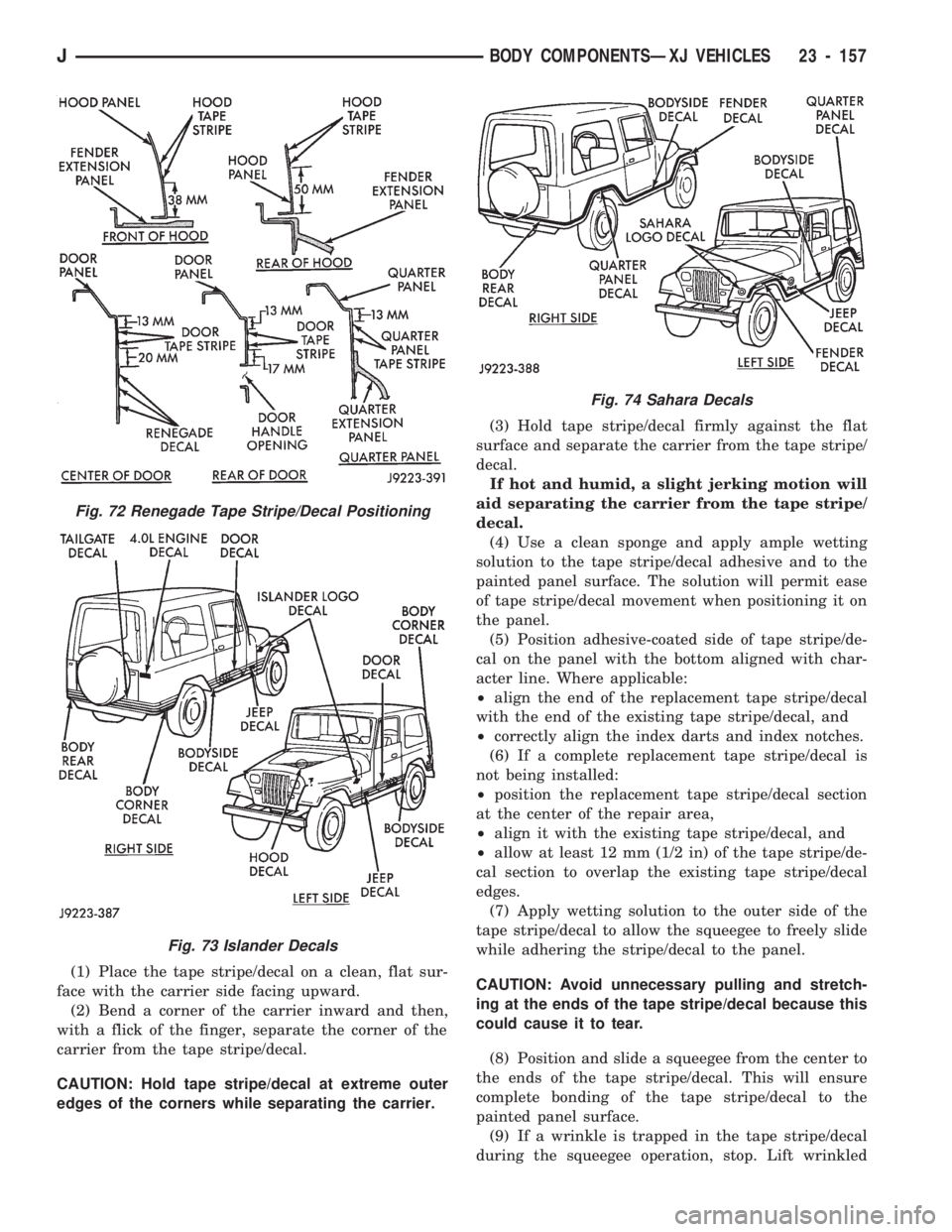
Fig. 72 Renegade Tape Stripe/Decal Positioning
Fig. 73 Islander Decals
Fig. 74 Sahara Decals
JBODY COMPONENTSÐXJ VEHICLES 23 - 157
Page 1628 of 1784
DOORS
INDEX
page page
Full-Metal Door Assist Handle.............. 175
Full-Metal Door Hinges................... 179
Full-Metal Door Key Lock Cylinder........... 178
Full-Metal Door Latch.................... 179
Full-Metal Door Latch External Release Handle . 178
Full-Metal Door Latch Inside Release and
Lock Handle.......................... 175
Full-Metal Door Service................... 181
Full-Metal Door Trim Panel................ 175Full-Metal Door Vent Window Glass......... 177
Full-Metal Door Waterdam................. 176
Full-Metal Door Weatherstrip Seals.......... 180
Full-Metal Door Window Glass.............. 178
Full-Metal Door Window Glass Regulator...... 177
Full-Metal Door Window Glass Regulator Handle. 175
Half-Metal Door Latch Striker............... 175
Half-Metal Soft Top Door.................. 173
HALF-METAL SOFT TOP DOOR
REMOVAL/DISASSEMBLY
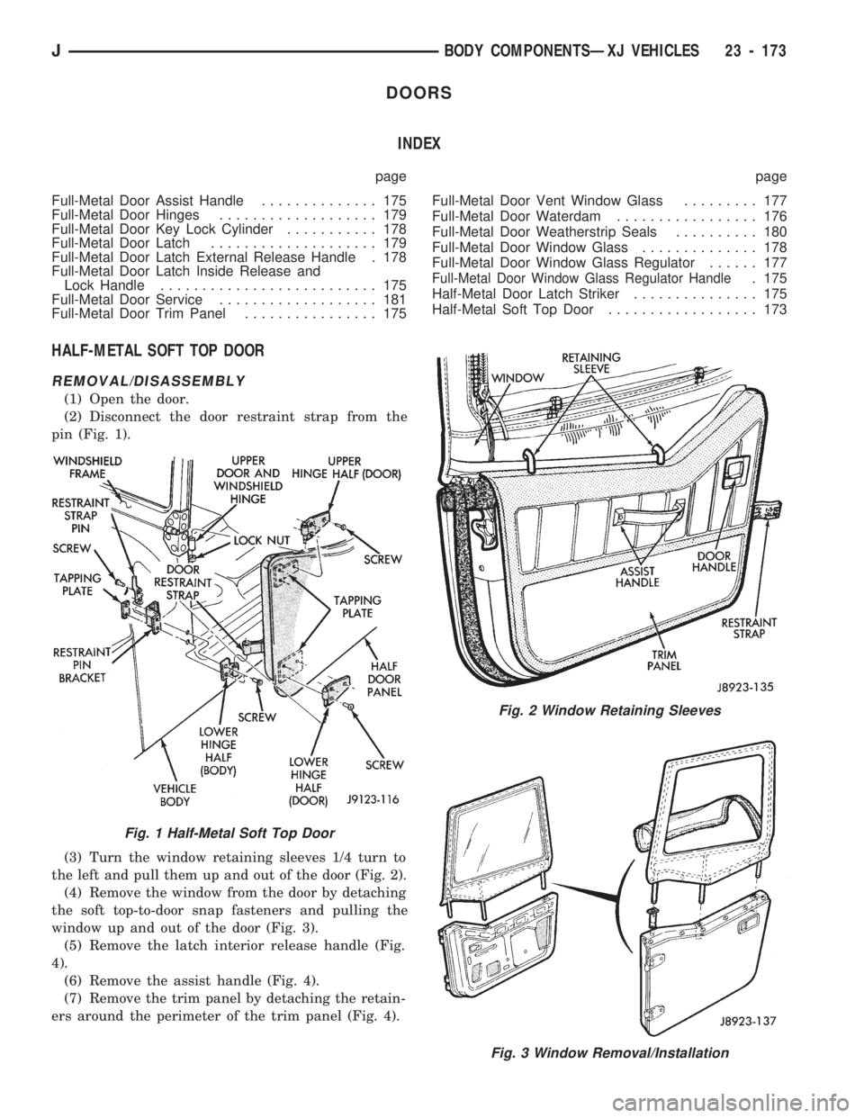
(1) Open the door.
(2) Disconnect the door restraint strap from the
pin (Fig. 1).
(3) Turn the window retaining sleeves 1/4 turn to
the left and pull them up and out of the door (Fig. 2).
(4) Remove the window from the door by detaching
the soft top-to-door snap fasteners and pulling the
window up and out of the door (Fig. 3).
(5) Remove the latch interior release handle (Fig.
4).
(6) Remove the assist handle (Fig. 4).
(7) Remove the trim panel by detaching the retain-
ers around the perimeter of the trim panel (Fig. 4).
Fig. 2 Window Retaining Sleeves
Fig. 3 Window Removal/Installation
Fig. 1 Half-Metal Soft Top Door
JBODY COMPONENTSÐXJ VEHICLES 23 - 173
Page 1638 of 1784
FIXED WINDOW GLASS
INDEX
page page
Fixed Glass Water Leak Detection and Repair . 189
Hard Top Quarter Window Glass............ 188
Rearview Mirror......................... 183
Rearview Mirror Retaining Bracket........... 183
Service Information...................... 183Windshield Frame....................... 184
Windshield Frame Weatherstrip Seal......... 185
Windshield Glass........................ 185
Windshield Reveal Moulding............... 183
SERVICE INFORMATION
The following fixed window service information in-
cludes removal/installation procedures for the:
²windshield reveal moulding,
²rearview mirror,
²windshield frame,
²windshield frame weatherstrip seal,
²windshield glass (using both the short and the ex-
tended installation method), and
²hard top quarter (side) window glass.
WINDSHIELD REVEAL MOULDING
REMOVAL
(1) Disengage the reveal moulding around the pe-
rimeter of the windshield glass with an appropriate
tool.
(2) Remove the mouldings from the windshield
frame.
(3) Inspect the reveal moulding retainers. Replace
the moulding if it has broken, distorted or ineffective
retainers.
INSTALLATION
(1) Position the reveal mouldings on the wind-
shield frame.
(2) Attach the mouldings to the frame by tapping
each moulding with a rubber mallet to seat the re-
tainers.
REARVIEW MIRROR
REMOVAL/INSTALLATION
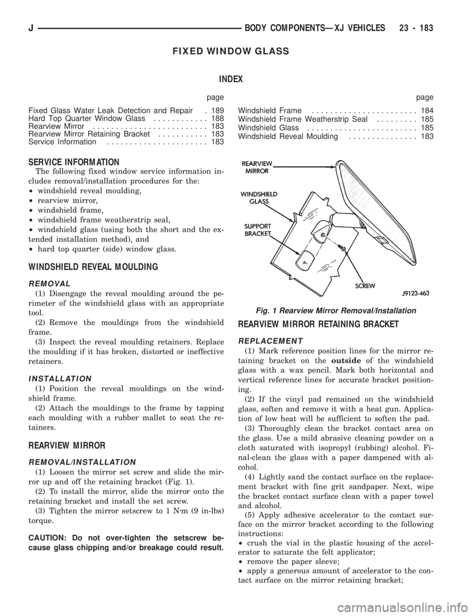
(1) Loosen the mirror set screw and slide the mir-
ror up and off the retaining bracket (Fig. 1).
(2) To install the mirror, slide the mirror onto the
retaining bracket and install the set screw.
(3) Tighten the mirror setscrew to 1 Nzm (9 in-lbs)
torque.
CAUTION: Do not over-tighten the setscrew be-
cause glass chipping and/or breakage could result.
REARVIEW MIRROR RETAINING BRACKET
REPLACEMENT
(1) Mark reference position lines for the mirror re-
taining bracket on theoutsideof the windshield
glass with a wax pencil. Mark both horizontal and
vertical reference lines for accurate bracket position-
ing.
(2) If the vinyl pad remained on the windshield
glass, soften and remove it with a heat gun. Applica-
tion of low heat will be sufficient to soften the pad.
(3) Thoroughly clean the bracket contact area on
the glass. Use a mild abrasive cleaning powder on a
cloth saturated with isopropyl (rubbing) alcohol. Fi-
nal-clean the glass with a paper dampened with al-
cohol.
(4) Lightly sand the contact surface on the replace-
ment bracket with fine grit sandpaper. Next, wipe
the bracket contact surface clean with a paper towel
and alcohol.
(5) Apply adhesive accelerator to the contact sur-
face on the mirror bracket according to the following
instructions:
²crush the vial in the plastic housing of the accel-
erator to saturate the felt applicator;
²remove the paper sleeve;
²apply a generous amount of accelerator to the con-
tact surface on the mirror retaining bracket;
Fig. 1 Rearview Mirror Removal/Installation
JBODY COMPONENTSÐXJ VEHICLES 23 - 183
Page 1645 of 1784
INTERIOR COMPONENTS
INDEX
page page
Carpet/Floor Mats....................... 198
Floor Consoles......................... 197
Front Shoulder Belts..................... 196
Glove Box............................. 194
Instrument Cluster and Gauge Housings...... 190
Instrument Cluster Bezel.................. 191Instrument Panel........................ 190
Instrument Panel Components.............. 191
Instrument Panel Service.................. 192
Rear Shoulder Belts..................... 196
Seats................................ 195
Sunvisors............................. 196
INSTRUMENT PANEL
SERVICE INFORMATION
The instrument panel is constructed of sheet metal
and is attached to cowl panel with screws. The in-
strument panel and defroster grille pad is attached
to the instrument panel with screws.
INSTRUMENT CLUSTER AND GAUGE HOUSINGS
REMOVAL
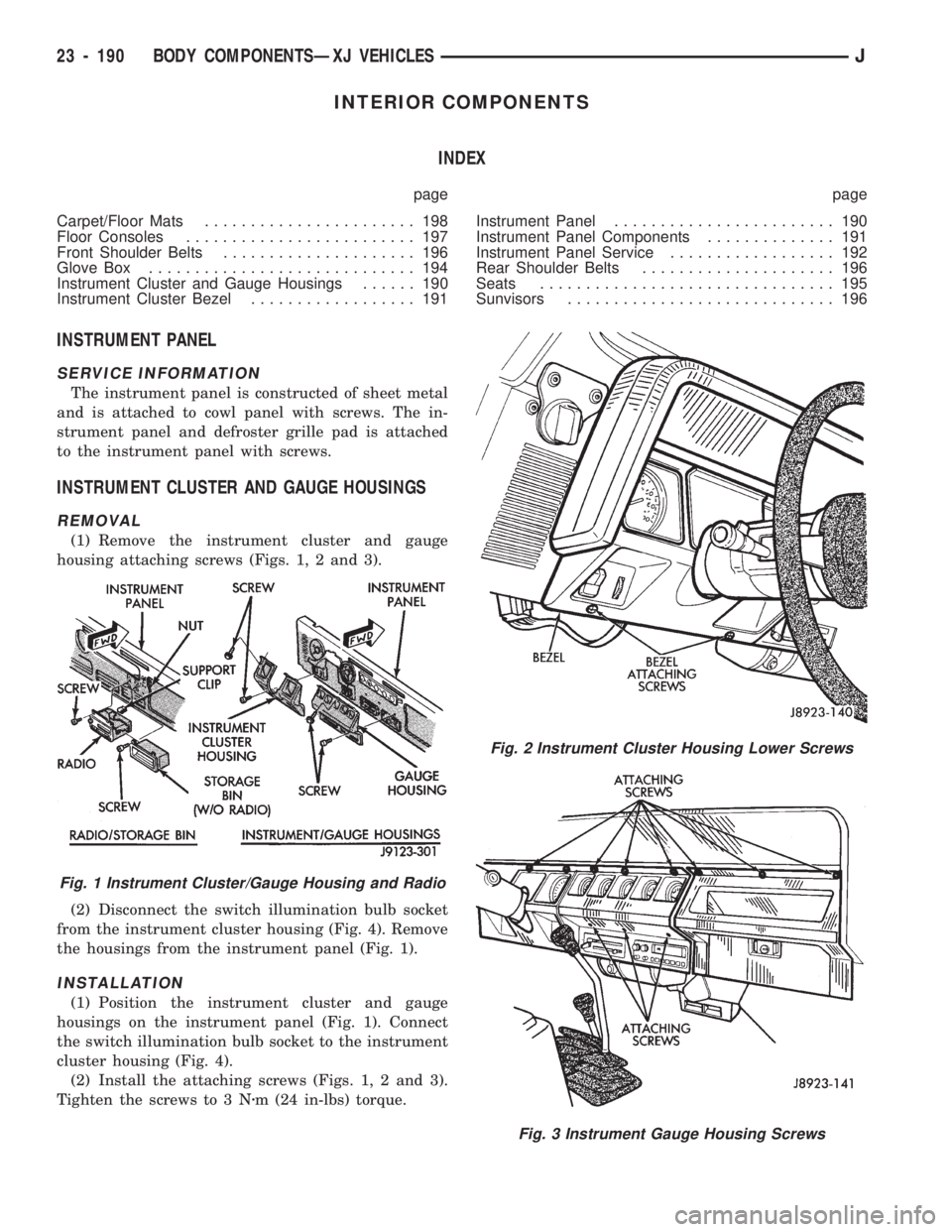
(1) Remove the instrument cluster and gauge
housing attaching screws (Figs. 1, 2 and 3).
(2) Disconnect the switch illumination bulb socket
from the instrument cluster housing (Fig. 4). Remove
the housings from the instrument panel (Fig. 1).
INSTALLATION
(1) Position the instrument cluster and gauge
housings on the instrument panel (Fig. 1). Connect
the switch illumination bulb socket to the instrument
cluster housing (Fig. 4).
(2) Install the attaching screws (Figs. 1, 2 and 3).
Tighten the screws to 3 Nzm (24 in-lbs) torque.
Fig. 2 Instrument Cluster Housing Lower Screws
Fig. 3 Instrument Gauge Housing Screws
Fig. 1 Instrument Cluster/Gauge Housing and Radio
23 - 190 BODY COMPONENTSÐXJ VEHICLESJ
Page 1656 of 1784
PAINT APPLICATION
INDEX
page page
Accent Paint........................... 202
Base/Color Coat........................ 201
Basecoat/Clearcoat...................... 202
Body Undercoat......................... 203
Buffing and Polishing..................... 203
Exterior Body Colors..................... 204Paint Repair on Galvanized Metals.......... 202
Plastic Components...................... 203
Primer................................ 201
Stone Chip Protection.................... 201
Surface Preparation...................... 201
SURFACE PREPARATION
Proper surface preparation is the key to top-quality
body panel refinishing. The bare metal must be
cleaned, de-greased, de-waxed and treated with phos-
phate.
Always clean the panel surface with a wax and
grease removal solution, and then wipe the surface
with a tack rag before applying primer or paint.
Cleaning will also remove any residual silicone from
the painted surface.
Body putty that is procured from a major supplier
is highly recommended. If a synthetic body filler is to
be used, it should also be a quality product.
STONE CHIP PROTECTION
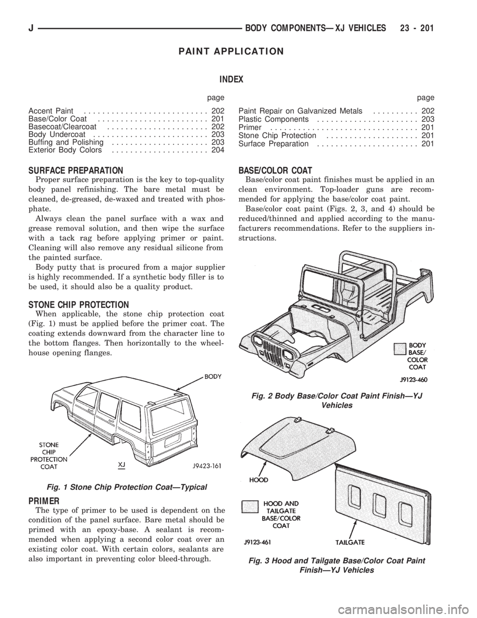
When applicable, the stone chip protection coat
(Fig. 1) must be applied before the primer coat. The
coating extends downward from the character line to
the bottom flanges. Then horizontally to the wheel-
house opening flanges.
PRIMER
The type of primer to be used is dependent on the
condition of the panel surface. Bare metal should be
primed with an epoxy-base. A sealant is recom-
mended when applying a second color coat over an
existing color coat. With certain colors, sealants are
also important in preventing color bleed-through.
BASE/COLOR COAT
Base/color coat paint finishes must be applied in an
clean environment. Top-loader guns are recom-
mended for applying the base/color coat paint.
Base/color coat paint (Figs. 2, 3, and 4) should be
reduced/thinned and applied according to the manu-
facturers recommendations. Refer to the suppliers in-
structions.
Fig. 2 Body Base/Color Coat Paint FinishÐYJ
Vehicles
Fig. 3 Hood and Tailgate Base/Color Coat Paint
FinishÐYJ Vehicles
Fig. 1 Stone Chip Protection CoatÐTypical
JBODY COMPONENTSÐXJ VEHICLES 23 - 201