1994 JEEP CHEROKEE index
[x] Cancel search: indexPage 1664 of 1784
HEATING AND AIR CONDITIONING
CONTENTS
page page
CLIMATE CONTROL SYSTEMÐXJ VEHICLES . 22
CLIMATE CONTROL SYSTEMÐYJ VEHICLES . 37
COMPRESSOR OVERHAUL............... 17
GENERAL INFORMATION.................. 1SERVICE DIAGNOSISÐELECTRICAL........ 14
SERVICE DIAGNOSISÐMECHANICAL........ 8
TORQUE SPECIFICATIONS................ 45
GENERAL INFORMATION
INDEX
page page
A/C Operation............................ 1
Compressor Oil Level...................... 6
Pressure Gauge and Manifold Assembly........ 2
Refrigerant (R-12)......................... 1
Service Precautions........................ 2Service Valves........................... 3
System Charge........................... 5
System Discharge......................... 4
System Evacuation........................ 4
A/C OPERATION
The compressor increases the pressure and temper-
ature of the refrigerant. The heated refrigerant vapor
is then pumped into the condenser where it cools by
the air passing over the condenser fins. As the refrig-
erant cools in the condenser, it condenses into a liq-
uid. Still under high pressure, the liquid refrigerant
passes into the receiver. The receiver acts as a reser-
voir to furnish refrigerant to the expansion (H) valve
at all times. From the receiver, the high pressure liq-
uid refrigerant passes to the expansion (H) valve.
The expansion (H) valve meters refrigerant into the
evaporator where a low pressure is maintained by
the suction side of the compressor. As it enters the
evaporator, the refrigerant immediately begins to
boil by absorbing heat from the air passing over the
evaporator core. Having given up its heat to boil the
refrigerant, the air is cooled and passes into the pas-
senger compartment of the vehicle. From the evapo-
rator the vaporized refrigerant is drawn back to the
compressor to repeat the cycle.
REFRIGERANT (R-12)
It is illegal to release R-12 into the atmosphere.
SAFETY PRECAUTIONS
WARNING: EXTREME CARE MUST BE TAKEN TO
PREVENT ANY LIQUID REFRIGERANT FROM COM-
ING IN CONTACT WITH THE SKIN AND ESPE-
CIALLY THE EYES. ALWAYS WEAR SAFETYGOGGLES WHEN SERVICING ANY PART OF THE
REFRIGERANT SYSTEM. IF EYE CONTACT IS
MADE, APPLY A FEW DROPS OF MINERAL OIL TO
THE EYES AND FLUSH WITH WATER FOR SEV-
ERAL MINUTES. SEEK MEDICAL ATTENTION IMME-
DIATELY.
The refrigerant used in the air conditioner system
is Refrigerant-12 (R-12). R-12 is nonexplosive, non-
flammable, non-corrosive, has practically no odor and
is heavier than air. Although it is classified as a safe
refrigerant, certain precautions must be observed to
protect the parts involved and the person who is
working on the unit. Liquid R-12, at normal atmo-
sphere pressures and temperatures, evaporates so
quickly that it has the tendency to freeze anything it
contacts.
WARNING: TO AVOID A DANGEROUS EXPLOSION,
NEVER WELD OR STEAM CLEAN NEAR AIR CON-
DITIONING LINES OR COMPONENTS. DO NOT
HEAT R-12 ABOVE 52ÉC (125ÉF).
The R-12 in the system is always under pressure.
Because the system is tightly sealed, heat applied to
any part could cause this pressure to build up exces-
sively.
JHEATING AND AIR CONDITIONING 24 - 1
Page 1680 of 1784
COMPRESSOR OVERHAUL
INDEX
page page
Compressor............................. 17
Compressor Isolation...................... 17
Description............................. 17Magnetic Clutch......................... 18
Purging Compressor of Air................. 17
DESCRIPTION
The A/C system uses a Sanden compressor. This
compressor is a 7 piston design. Designated the SD-
709, the compressor is mounted on the front right
side of the engine and is driven by a serpentine belt.
System lubrication is provided by 135cc615cc (4.6
cu. in.60.5 cu. in.) of 500 viscosity refrigerant oil.
The clutch used on the compressor consists of 3 ba-
sic components: the pulley, front plate and the field
coil. The pulley and field coil are attached to the
front head of the compressor with tapered snap rings.
The hub is keyed to the compressor shaft and is re-
tained on the shaft with a self-locking nut. Special
service tools are required to remove and install the
clutch plate on the compressor shaft.
COMPRESSOR ISOLATION
It is not necessary to discharge the system for com-
pressor removal. The compressor can be isolated from
the remainder of the system and eliminate the need
for recharging when performing compressor service.
(1) Connect pressure gauge and manifold.
(2) Close both gauge hand valves.
(3) Mid-position both service valves.
WARNING: USE EXTREME CAUTION WHEN THE
ENGINE IS OPERATING. DO NOT STAND IN A DI-
RECT LINE WITH THE FAN. DO NOT PUT YOUR
HANDS NEAR THE PULLEYS, BELTS OR FAN. DO
NOT WEAR LOOSE CLOTHING.
(4) Start the engine and operate the air condition-
ing system.
(5) Turn the suction service valve slowly clockwise
toward the front seated position.
(6) When pressure drops to zero, stop the engine
and compressor and quickly finish front-seating the
suction service valve.
(7) Front-seat the discharge service valve.
(8) Loosen the oil level check plug slowly to re-
lease any internal pressure in the compressor.
The compressor is now isolated from the remainder
of the system.
The service valves can be removed from the com-
pressor.
PURGING COMPRESSOR OF AIR
The compressor must be purged of air whenever it
has been isolated for an oil level check or other ser-
vice procedures without discharging the entire sys-
tem.
(1) Cap the service gauge ports on both of the ser-
vice valves.
(2) Back-seat the suction service valve to allow the
system refrigerant to enter the compressor.
(3) Place the discharge service valve in the mid-po-
sition or cracked-position.
(4) Loosen the discharge service valve gauge port
cap to permit the refrigerant to force any air out of
the compressor.
(5) Back-seat the discharge service valve and
tighten the gauge port cap.
(6) The compressor is now ready for service.
COMPRESSOR
REMOVAL
(1) Isolate the compressor.
(2) Disconnect negative cable from battery.
(3) Disconnect the clutch lead wire.
(4) Remove the discharge and inlet (suction) ser-
vice valves from the compressor. Plug or tape all the
openings.
(5) Remove the serpentine drive belt (refer to
Group 7, Cooling System for the proper procedure).
(6) Remove the bolts and lift the compressor from
the mounting bracket (Figs. 1 and 2).
INSTALLATION
If a replacement compressor is being installed;
check the oil level. Add or subtract oil as neces-
sary and install the magnetic clutch on the com-
pressor.
(1) If the mounting bracket was removed, install
the bracket to the block. Tighten the mounting bolts
to 27 NIm (20 ft. lbs.) torque.
(2) Install the compressor on the mounting
bracket. Tighten the bolts to 27 NIm (20 ft. lbs.)
torque.
(3) Install the serpentine drive belt (refer to Group
7, Cooling System for the proper procedure).
(4) Tighten the serpentine drive belt to the speci-
fied tension.
²New belt tensionÐ800-900 N (180-200 lb-f).
JHEATING AND AIR CONDITIONING 24 - 17
Page 1685 of 1784
CLIMATE CONTROL SYSTEMÐXJ VEHICLES
INDEX
page page
A/C Recirculating Air Door Vacuum Motor
Replacement.......................... 31
Blower Motor Resistors Replacement......... 35
Blower Motor/Fan Replacement.............. 26
CondenserÐ4.0L Engines.................. 32
Condenser/Receiver DrierÐ2.5L Engines....... 31
Defroster Duct Replacement................ 29
Description............................. 22
Evaporator Coil.......................... 34
Evaporator/Blower Housing................. 33Expansion (H) Valve...................... 35
Heater and A/C Control Panel Replacement.... 26
Heater Control Cable Replacement........... 30
Heater Core............................ 28
Heater Core Housing Replacement........... 29
Heater/Defroster/Instrument Panel Outlet Door
Vacuum Motor Replacement............... 30
Receiver DrierÐ4.0L Engines............... 32
Temperature Control Thermostat............. 35
DESCRIPTION
The Climate Control System combines air condi-
tioning, heating and ventilating capabilities for vehi-
cles equipped with air conditioning. Vehicles without
air conditioning perform heating and ventilating
functions without the air conditioning evaporator.
Both systems consist basically of 2 parts:
²Blower and Air Inlet Assembly
²Heater Core and Air Distribution Assembly
These assemblies, initially installed as a single
unit, may be removed separately from under the in-
strument panel as required for service.
HEATER SYSTEM
The heater system is a blend air type. Outside air
is heated and then blended in varying amounts with
cooler outside air to obtain the desired discharge
temperature. A heater coolant valve provides full
flow to the heater core for all heating modes. The
heater coolant valve remains closed for the ventila-
tion mode, allowing discharge air to approach the
outside ambient air temperature.
AIR CONDITIONING SYSTEM
The air conditioning system has an evaporator to
cool and dehumidify the incoming outside air prior to
blending with the heated air. The evaporator is in
operation during the A/C mode and also in the de-
frost mode for defogging purposes. The evaporator is
not in operation at ambient temperatures below ap-
proximately -1ÉC (30ÉF). To maintain minimum evap-
orator temperature, a fixed thermostat setting switch
cycles the compressor clutch. The blower is operatingthe heater or air conditioning systems, except the
OFF mode. In this mode (OFF) the blower and the
outside air are shut off.
The cooling unit is mounted on the dash panel and
the cooled air is discharged from the instrument
panel registers. The registers are adjusted to provide
general or localized cooling.
SIGHT GLASS
The sight glass is located on top of the receiver/
drier. The sight glass provides a visual check of the
system refrigerant level. A continuous stream of bub-
bles will appear in the sight glass when the system
charge is low. Bubbles will not appear when the sys-
tem is fully charged.
LOW PRESSURE SWITCH
The low pressure switch disengages the magnetic
clutch if the pressure in the system drops below 193
kPa (28 psi). This will occur with a loss in refriger-
ant or with cold ambient temperature.
HEATER VALVE
The heater valve regulates coolant flow to the
heater core. It requires vacuum to shut off flow to
the heater core.
These vehicles are equipped with a bypass-type
heater water valve. When the heater valve is closed,
coolant flow to the heater core is bypassed back to
the engine. When the heater valve is open, coolant is
directed through the heater core and back to the en-
gine.
24 - 22 HEATING AND AIR CONDITIONINGJ
Page 1700 of 1784
CLIMATE CONTROL SYSTEMÐYJ VEHICLES
INDEX
page page
A/C Blower Motor........................ 43
A/C Condenser.......................... 42
A/C Control Panel........................ 41
Blower Motor (Heating).................... 40
Blower Motor/Air Door Motor Switch Replacement . 39
Defroster Nozzle and Duct................. 40
Description (Air Conditioning)................ 41
Description (Heating)...................... 37
Evaporator and Housing................... 42
Expansion (H) Valve...................... 43Fresh Air Door Vacuum Motor............... 41
Fresh Air Intake Duct..................... 41
Fresh Air Ventilation...................... 39
Heater Control Panel Replacement........... 39
Heater Core and Housing.................. 40
Heater/Defroster Operation................. 37
Receiver-Drier Replacement................ 42
Sight Glass............................. 41
Vent Door Control Cables.................. 39
DESCRIPTION (HEATING)
A blend-air heating system is used in YJ vehicles.
The blend-air system provides a constant flow of en-
gine coolant through the heater core.
The temperature of heated air entering the passen-
ger compartment is controlled by regulating the
quantity of air flow through the heater core. This is
accomplished by blending a controlled amount of un-
heated air from outside the vehicle with heated air
from the heater core.
HEATER/DEFROSTER OPERATION
The heater core is connected to the engine cooling
system. It operates on the circulation of heated en-
gine coolant through the core and a supply of fresh
air drawn in through the intake grille on the cowl.
Engine coolant flows through the heater core at all
times.
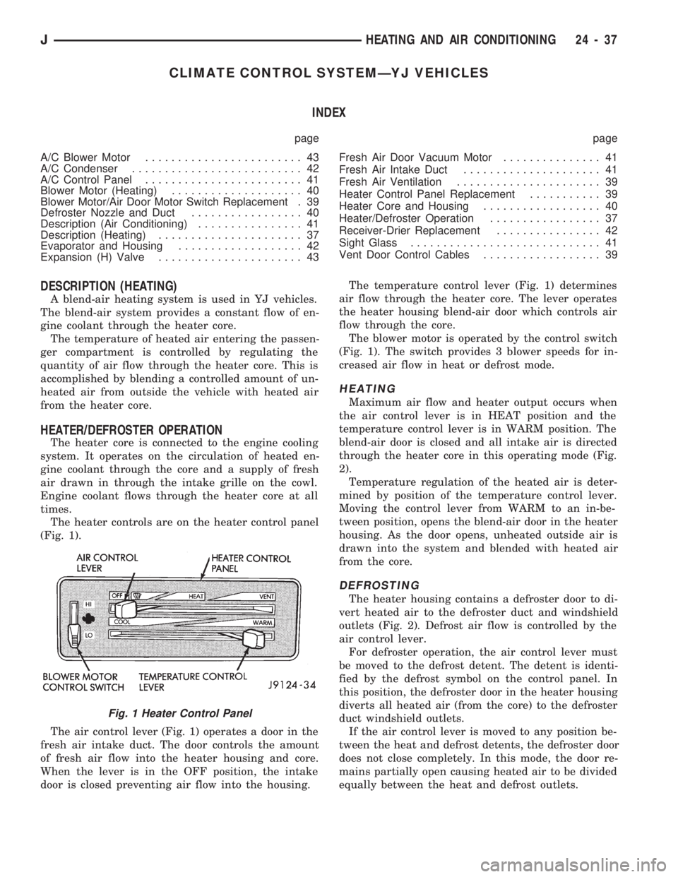
The heater controls are on the heater control panel
(Fig. 1).
The air control lever (Fig. 1) operates a door in the
fresh air intake duct. The door controls the amount
of fresh air flow into the heater housing and core.
When the lever is in the OFF position, the intake
door is closed preventing air flow into the housing.The temperature control lever (Fig. 1) determines
air flow through the heater core. The lever operates
the heater housing blend-air door which controls air
flow through the core.
The blower motor is operated by the control switch
(Fig. 1). The switch provides 3 blower speeds for in-
creased air flow in heat or defrost mode.
HEATING
Maximum air flow and heater output occurs when
the air control lever is in HEAT position and the
temperature control lever is in WARM position. The
blend-air door is closed and all intake air is directed
through the heater core in this operating mode (Fig.
2).
Temperature regulation of the heated air is deter-
mined by position of the temperature control lever.
Moving the control lever from WARM to an in-be-
tween position, opens the blend-air door in the heater
housing. As the door opens, unheated outside air is
drawn into the system and blended with heated air
from the core.
DEFROSTING
The heater housing contains a defroster door to di-
vert heated air to the defroster duct and windshield
outlets (Fig. 2). Defrost air flow is controlled by the
air control lever.
For defroster operation, the air control lever must
be moved to the defrost detent. The detent is identi-
fied by the defrost symbol on the control panel. In
this position, the defroster door in the heater housing
diverts all heated air (from the core) to the defroster
duct windshield outlets.
If the air control lever is moved to any position be-
tween the heat and defrost detents, the defroster door
does not close completely. In this mode, the door re-
mains partially open causing heated air to be divided
equally between the heat and defrost outlets.
Fig. 1 Heater Control Panel
JHEATING AND AIR CONDITIONING 24 - 37
Page 1719 of 1784
EMISSION CONTROL SYSTEMS
CONTENTS
page page
COMPONENT REMOVAL/INSTALLATION...... 8
EVAPORATIVE EMISSION CONTROLS....... 4EXHAUST EMISSION CONTROLS........... 7
GENERAL INFORMATION.................. 1
GENERAL INFORMATION
INDEX
page page
DRB Scan Tool........................... 2
Service Reminder Indicator (SRI) Lamp......... 1Vacuum Hose Routing Schematics............ 1
Vehicle Emission Control Information (VECI) Label . 1
SERVICE REMINDER INDICATOR (SRI) LAMP
The instrument panel mounted SRI lamp was for-
merly referred to as the emission maintenance re-
minder (EMR) lamp. It isnot usedon any Jeep
model for the 1994 model year.
VEHICLE EMISSION CONTROL INFORMATION
(VECI) LABEL
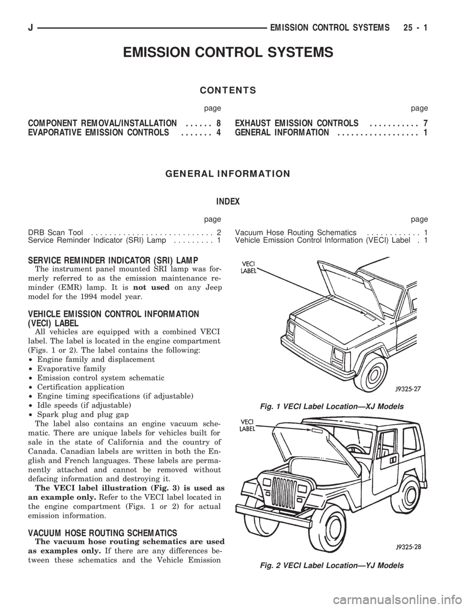
All vehicles are equipped with a combined VECI
label. The label is located in the engine compartment
(Figs. 1 or 2). The label contains the following:
²Engine family and displacement
²Evaporative family
²Emission control system schematic
²Certification application
²Engine timing specifications (if adjustable)
²Idle speeds (if adjustable)
²Spark plug and plug gap
The label also contains an engine vacuum sche-
matic. There are unique labels for vehicles built for
sale in the state of California and the country of
Canada. Canadian labels are written in both the En-
glish and French languages. These labels are perma-
nently attached and cannot be removed without
defacing information and destroying it.
The VECI label illustration (Fig. 3) is used as
an example only.Refer to the VECI label located in
the engine compartment (Figs. 1 or 2) for actual
emission information.
VACUUM HOSE ROUTING SCHEMATICS
The vacuum hose routing schematics are used
as examples only.If there are any differences be-
tween these schematics and the Vehicle Emission
Fig. 1 VECI Label LocationÐXJ Models
Fig. 2 VECI Label LocationÐYJ Models
JEMISSION CONTROL SYSTEMS 25 - 1
Page 1722 of 1784
EVAPORATIVE EMISSION CONTROLS
INDEX
page page
Crankcase Ventilation System................ 5
EVAP (Evaporation) Control System........... 4
EVAP Canister........................... 4Fuel Tank Filler Tube Cap.................. 4
Pressure Relief/Rollover Valve................ 5
EVAP (EVAPORATION) CONTROL SYSTEM
GENERAL INFORMATION
The function of the EVAP control system is to pre-
vent the emissions of gasoline vapors from the fuel
tank into the atmosphere. When fuel evaporates in
the fuel tank, the vapors pass through vent hoses or
tubes to a carbon filled EVAP canister. They are
temporarily held in the canister until they can be
drawn into the intake manifold when the engine is
running.
The EVAP canister is a feature on all models for
the storage of fuel vapors from the fuel tank.
The hoses used in this system are specially
manufactured. If replacement becomes neces-
sary, it is important to use only fuel resistant
hose.
EVAP CANISTER
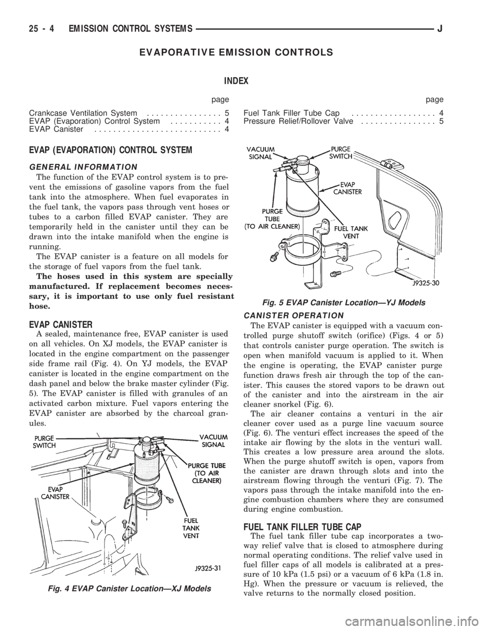
A sealed, maintenance free, EVAP canister is used
on all vehicles. On XJ models, the EVAP canister is
located in the engine compartment on the passenger
side frame rail (Fig. 4). On YJ models, the EVAP
canister is located in the engine compartment on the
dash panel and below the brake master cylinder (Fig.
5). The EVAP canister is filled with granules of an
activated carbon mixture. Fuel vapors entering the
EVAP canister are absorbed by the charcoal gran-
ules.
CANISTER OPERATION
The EVAP canister is equipped with a vacuum con-
trolled purge shutoff switch (orifice) (Figs. 4 or 5)
that controls canister purge operation. The switch is
open when manifold vacuum is applied to it. When
the engine is operating, the EVAP canister purge
function draws fresh air through the top of the can-
ister. This causes the stored vapors to be drawn out
of the canister and into the airstream in the air
cleaner snorkel (Fig. 6).
The air cleaner contains a venturi in the air
cleaner cover used as a purge line vacuum source
(Fig. 6). The venturi effect increases the speed of the
intake air flowing by the slots in the venturi wall.
This creates a low pressure area around the slots.
When the purge shutoff switch is open, vapors from
the canister are drawn through slots and into the
airstream flowing through the venturi (Fig. 7). The
vapors pass through the intake manifold into the en-
gine combustion chambers where they are consumed
during engine combustion.
FUEL TANK FILLER TUBE CAP
The fuel tank filler tube cap incorporates a two-
way relief valve that is closed to atmosphere during
normal operating conditions. The relief valve used in
fuel filler caps of all models is calibrated at a pres-
sure of 10 kPa (1.5 psi) or a vacuum of 6 kPa (1.8 in.
Hg). When the pressure or vacuum is relieved, the
valve returns to the normally closed position.
Fig. 4 EVAP Canister LocationÐXJ Models
Fig. 5 EVAP Canister LocationÐYJ Models
25 - 4 EMISSION CONTROL SYSTEMSJ
Page 1725 of 1784
EXHAUST EMISSION CONTROLS
INDEX
page page
Air Cleaner.............................. 7Oxygen (O2S) Sensor...................... 7
AIR CLEANER
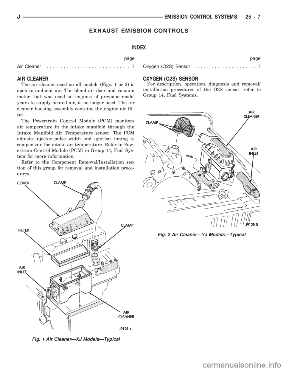
The air cleaner used on all models (Figs. 1 or 2) is
open to ambient air. The blend air door and vacuum
motor that was used on engines of previous model
years to supply heated air, is no longer used. The air
cleaner housing assembly contains the engine air fil-
ter.
The Powertrain Control Module (PCM) monitors
air temperature in the intake manifold through the
Intake Manifold Air Temperature sensor. The PCM
adjusts injector pulse width and ignition timing to
compensate for intake air temperature. Refer to Pow-
ertrain Control Module (PCM) in Group 14, Fuel Sys-
tem for more information.
Refer to the Component Removal/Installation sec-
tion of this group for removal and installation proce-
dures.
OXYGEN (O2S) SENSOR
For description, operation, diagnosis and removal/
installation procedures of the O2S sensor, refer to
Group 14, Fuel Systems.
Fig. 2 Air CleanerÐYJ ModelsÐTypical
Fig. 1 Air CleanerÐXJ ModelsÐTypical
JEMISSION CONTROL SYSTEMS 25 - 7
Page 1726 of 1784

COMPONENT REMOVAL/INSTALLATION
INDEX
page page
Air Cleaner Housing....................... 8
Air Filter................................ 9
Coolant Temperature Sensor................. 9
EVAP Canister........................... 9Fuel Tank Filler Tube Cap.................. 9
Oxygen (O2S) Sensor...................... 9
Powertrain Control Module (PCM)............. 9
Pressure Relief/Rollover Valve................ 9
AIR CLEANER HOUSING
REMOVAL
(1) Unlock clean air hose clamp (Figs. 3 or 4) at
air cleaner cover. To unlock the clamp, attach adjust-
able pliers to clamp and rotate pliers as shown in fig-
ure 3. Remove clean air hose at cover.
(2) Disconnect vacuum lines at air cleaner hous-
ing.
(3) YJ Models: Release the three over-center type
clamps securing the housing to the housing bracket.
XJ Models: Remove the housing cover and remove
air filter. Remove two bolts and one nut.
(4) Release the air cleaner housing from the ambi-
ent air inlet and remove housing from vehicle.
INSTALLATION
(1) Position air cleaner housing to body and ambi-
ent air inlet.
(2) YJ Models: Lock the three over-center type
clamps securing the housing to the housing bracket.
XJ Models: Install two bolts and one nut to housing.Fig. 3 Air CleanerÐXJ ModelsÐTypical
Fig. 4 Air CleanerÐYJ ModelsÐTypical
Fig. 5 Clamp Removal
25 - 8 EMISSION CONTROL SYSTEMSJ