Page 1382 of 1784
valve shaft. Tighten lever attaching nut to 16 Nzm
(12 ft. lbs.) torque.
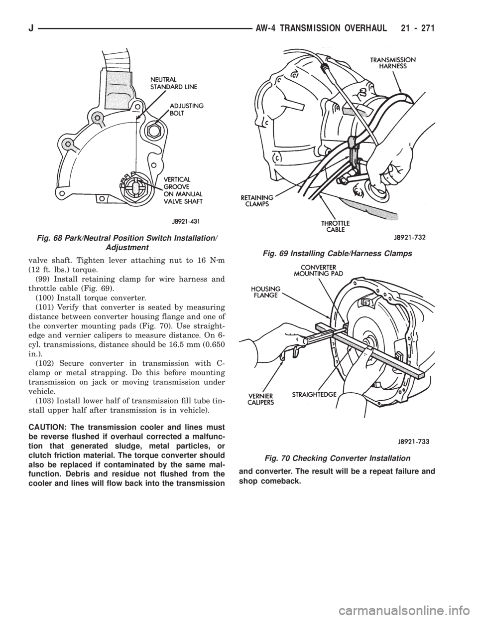
(99) Install retaining clamp for wire harness and
throttle cable (Fig. 69).
(100) Install torque converter.
(101) Verify that converter is seated by measuring
distance between converter housing flange and one of
the converter mounting pads (Fig. 70). Use straight-
edge and vernier calipers to measure distance. On 6-
cyl. transmissions, distance should be 16.5 mm (0.650
in.).
(102) Secure converter in transmission with C-
clamp or metal strapping. Do this before mounting
transmission on jack or moving transmission under
vehicle.
(103) Install lower half of transmission fill tube (in-
stall upper half after transmission is in vehicle).
CAUTION: The transmission cooler and lines must
be reverse flushed if overhaul corrected a malfunc-
tion that generated sludge, metal particles, or
clutch friction material. The torque converter should
also be replaced if contaminated by the same mal-
function. Debris and residue not flushed from the
cooler and lines will flow back into the transmissionand converter. The result will be a repeat failure and
shop comeback.Fig. 69 Installing Cable/Harness Clamps
Fig. 70 Checking Converter Installation
Fig. 68 Park/Neutral Position Switch Installation/
Adjustment
JAW-4 TRANSMISSION OVERHAUL 21 - 271
Page 1383 of 1784
NP231 TRANSFER CASE
INDEX
page page
General Information...................... 272
Shift Linkage Adjustment.................. 275
Speedometer Service.................... 275
Transfer Case Assembly.................. 282
Transfer Case Disassembly and Overhaul..... 277Transfer Case Identification................ 273
Transfer Case Installation................. 276
Transfer Case Lubricant.................. 273
Transfer Case Removal................... 276
GENERAL INFORMATION
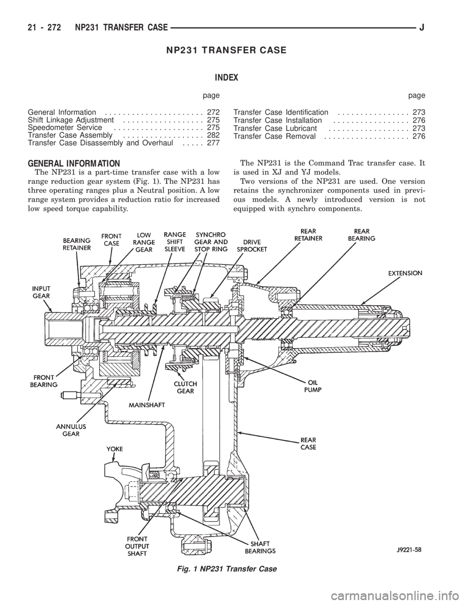
The NP231 is a part-time transfer case with a low
range reduction gear system (Fig. 1). The NP231 has
three operating ranges plus a Neutral position. A low
range system provides a reduction ratio for increased
low speed torque capability.The NP231 is the Command Trac transfer case. It
is used in XJ and YJ models.
Two versions of the NP231 are used. One version
retains the synchronizer components used in previ-
ous models. A newly introduced version is not
equipped with synchro components.
Fig. 1 NP231 Transfer Case
21 - 272 NP231 TRANSFER CASEJ
Page 1387 of 1784
TRANSFER CASE REMOVAL
(1) Shift transfer case into Neutral.
(2) Raise vehicle.
(3) Drain transfer case lubricant.
(4) Mark front and rear propeller shaft yokes for
alignment reference.
(5) Support transmission with jack stand.
(6) Remove rear crossmember, or skid plate.
(7) Disconnect front/rear propeller shafts at trans-
fer case.
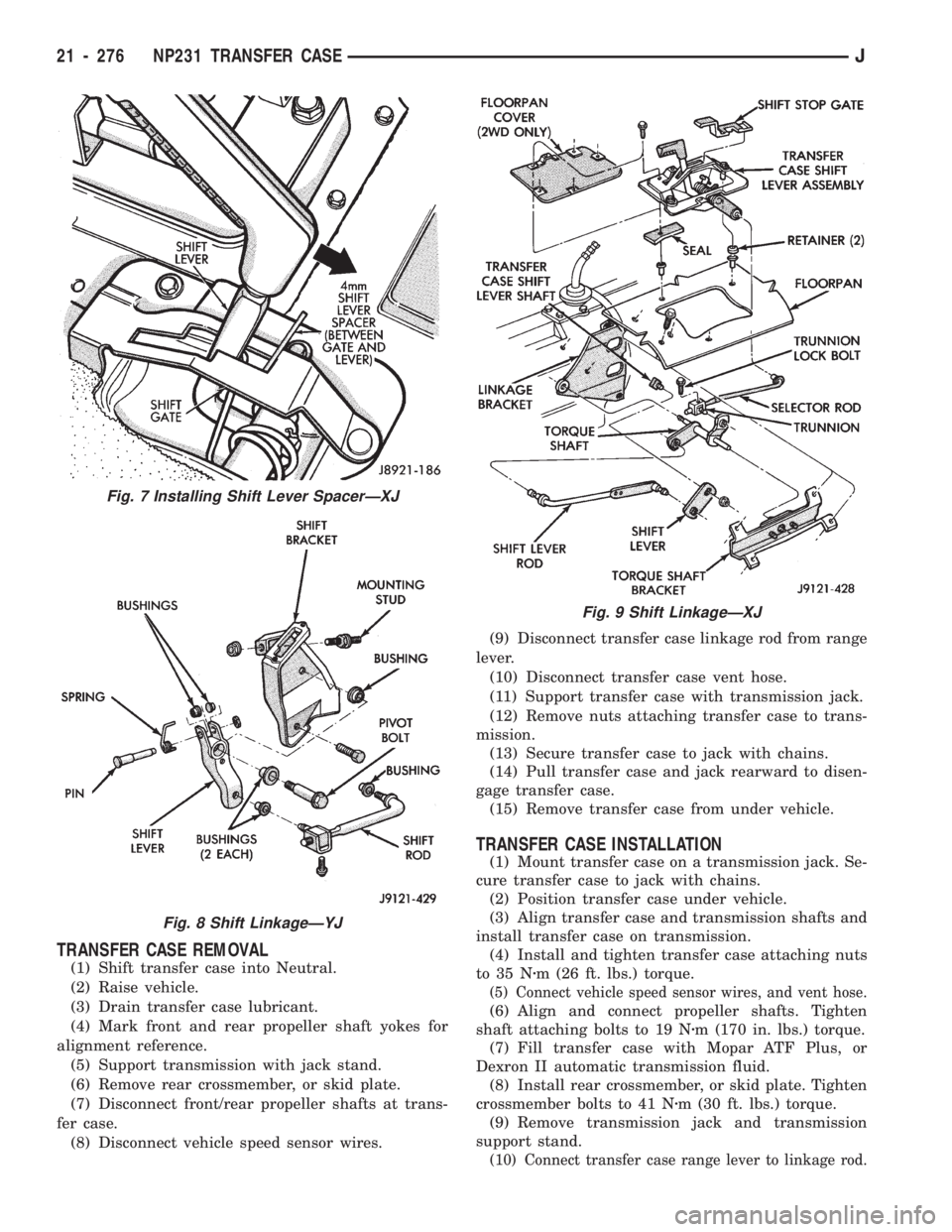
(8) Disconnect vehicle speed sensor wires.(9) Disconnect transfer case linkage rod from range
lever.
(10) Disconnect transfer case vent hose.
(11) Support transfer case with transmission jack.
(12) Remove nuts attaching transfer case to trans-
mission.
(13) Secure transfer case to jack with chains.
(14) Pull transfer case and jack rearward to disen-
gage transfer case.
(15) Remove transfer case from under vehicle.
TRANSFER CASE INSTALLATION
(1) Mount transfer case on a transmission jack. Se-
cure transfer case to jack with chains.
(2) Position transfer case under vehicle.
(3) Align transfer case and transmission shafts and
install transfer case on transmission.
(4) Install and tighten transfer case attaching nuts
to 35 Nzm (26 ft. lbs.) torque.
(5) Connect vehicle speed sensor wires, and vent hose.
(6) Align and connect propeller shafts. Tighten
shaft attaching bolts to 19 Nzm (170 in. lbs.) torque.
(7) Fill transfer case with Mopar ATF Plus, or
Dexron II automatic transmission fluid.
(8) Install rear crossmember, or skid plate. Tighten
crossmember bolts to 41 Nzm (30 ft. lbs.) torque.
(9) Remove transmission jack and transmission
support stand.
(10) Connect transfer case range lever to linkage rod.
Fig. 7 Installing Shift Lever SpacerÐXJ
Fig. 8 Shift LinkageÐYJ
Fig. 9 Shift LinkageÐXJ
21 - 276 NP231 TRANSFER CASEJ
Page 1395 of 1784
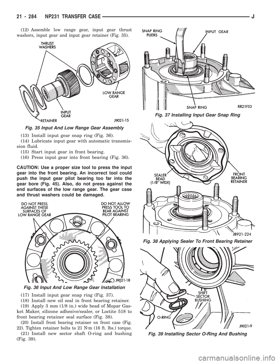
(12) Assemble low range gear, input gear thrust
washers, input gear and input gear retainer (Fig. 35).
(13) Install input gear snap ring (Fig. 36).
(14) Lubricate input gear with automatic transmis-
sion fluid.
(15) Start input gear in front bearing.
(16) Press input gear into front bearing (Fig. 36).
CAUTION: Use a proper size tool to press the input
gear into the front bearing. An incorrect tool could
push the input gear pilot bearing too far into the
gear bore (Fig. 45). Also, do not press against the
end surfaces of the low range gear. The gear case
and thrust washers could be damaged.
(17) Install input gear snap ring (Fig. 37).
(18) Install new oil seal in front bearing retainer.
(19) Apply 3 mm (1/8 in.) wide bead of Mopar Gas-
ket Maker, silicone adhesive/sealer, or Loctite 518 to
front bearing retainer seal surface (Fig. 38).
(20) Install front bearing retainer on front case (Fig.
22). Tighten retainer bolts to 21 Nzm (16 ft. lbs.) torque.
(21) Install new sector shaft O-ring and bushing
(Fig. 39).
Fig. 37 Installing Input Gear Snap Ring
Fig. 38 Applying Sealer To Front Bearing Retainer
Fig. 39 Installing Sector O-Ring And Bushing
Fig. 35 Input And Low Range Gear Assembly
Fig. 36 Input And Low Range Gear Installation
21 - 284 NP231 TRANSFER CASEJ
Page 1396 of 1784
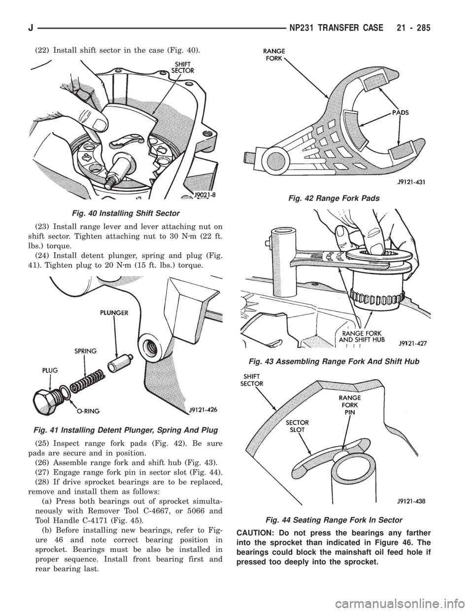
(22) Install shift sector in the case (Fig. 40).
(23) Install range lever and lever attaching nut on
shift sector. Tighten attaching nut to 30 Nzm (22 ft.
lbs.) torque.
(24) Install detent plunger, spring and plug (Fig.
41). Tighten plug to 20 Nzm (15 ft. lbs.) torque.
(25) Inspect range fork pads (Fig. 42). Be sure
pads are secure and in position.
(26) Assemble range fork and shift hub (Fig. 43).
(27) Engage range fork pin in sector slot (Fig. 44).
(28) If drive sprocket bearings are to be replaced,
remove and install them as follows:
(a) Press both bearings out of sprocket simulta-
neously with Remover Tool C-4667, or 5066 and
Tool Handle C-4171 (Fig. 45).
(b) Before installing new bearings, refer to Fig-
ure 46 and note correct bearing position in
sprocket. Bearings must be also be installed in
proper sequence. Install front bearing first and
rear bearing last.CAUTION: Do not press the bearings any farther
into the sprocket than indicated in Figure 46. The
bearings could block the mainshaft oil feed hole if
pressed too deeply into the sprocket.
Fig. 42 Range Fork Pads
Fig. 43 Assembling Range Fork And Shift Hub
Fig. 44 Seating Range Fork In Sector
Fig. 40 Installing Shift Sector
Fig. 41 Installing Detent Plunger, Spring And Plug
JNP231 TRANSFER CASE 21 - 285
Page 1399 of 1784
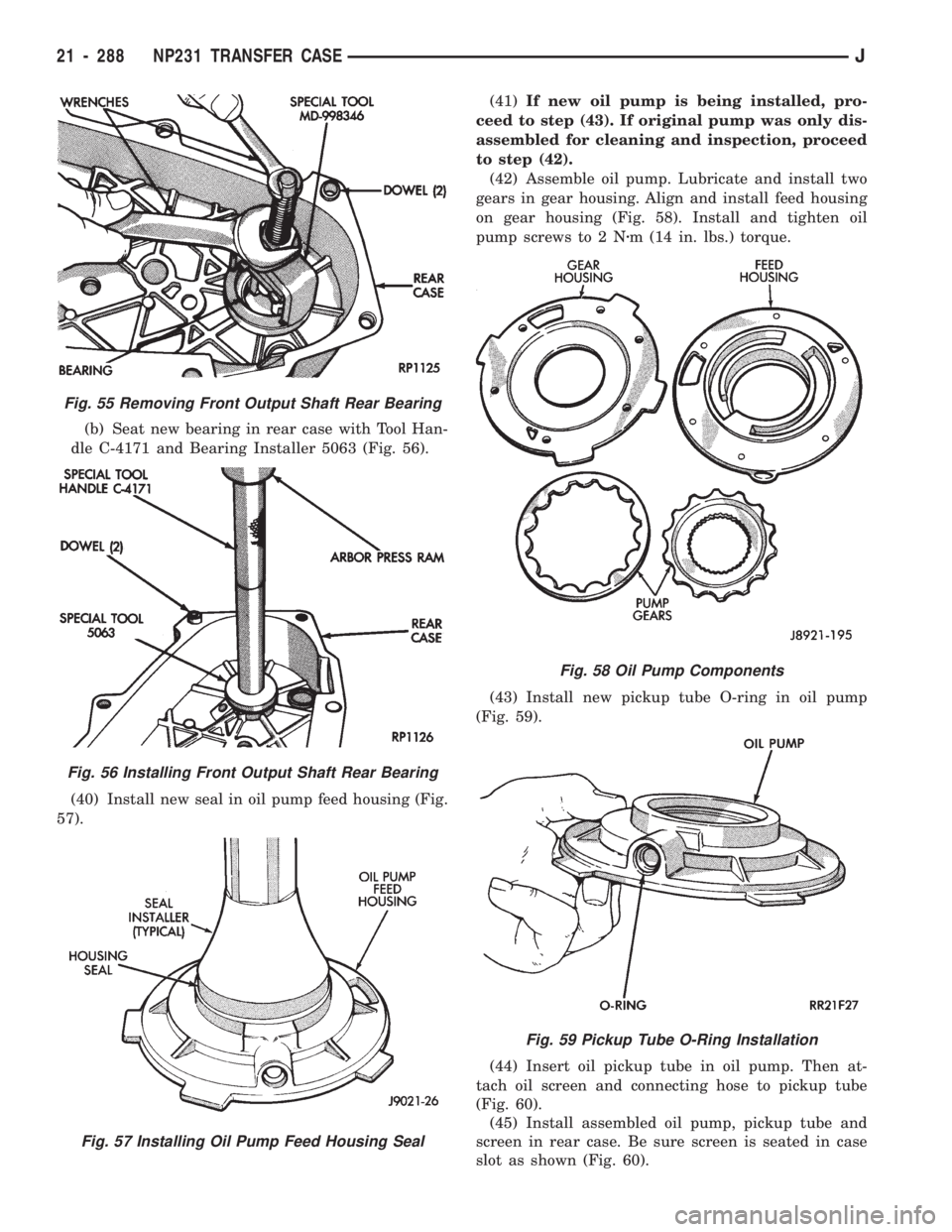
(b) Seat new bearing in rear case with Tool Han-
dle C-4171 and Bearing Installer 5063 (Fig. 56).
(40) Install new seal in oil pump feed housing (Fig.
57).(41)If new oil pump is being installed, pro-
ceed to step (43). If original pump was only dis-
assembled for cleaning and inspection, proceed
to step (42).
(42) Assemble oil pump. Lubricate and install two
gears in gear housing. Align and install feed housing
on gear housing (Fig. 58). Install and tighten oil
pump screws to 2 Nzm (14 in. lbs.) torque.
(43) Install new pickup tube O-ring in oil pump
(Fig. 59).
(44) Insert oil pickup tube in oil pump. Then at-
tach oil screen and connecting hose to pickup tube
(Fig. 60).
(45) Install assembled oil pump, pickup tube and
screen in rear case. Be sure screen is seated in case
slot as shown (Fig. 60).
Fig. 55 Removing Front Output Shaft Rear Bearing
Fig. 56 Installing Front Output Shaft Rear Bearing
Fig. 57 Installing Oil Pump Feed Housing Seal
Fig. 58 Oil Pump Components
Fig. 59 Pickup Tube O-Ring Installation
21 - 288 NP231 TRANSFER CASEJ
Page 1400 of 1784
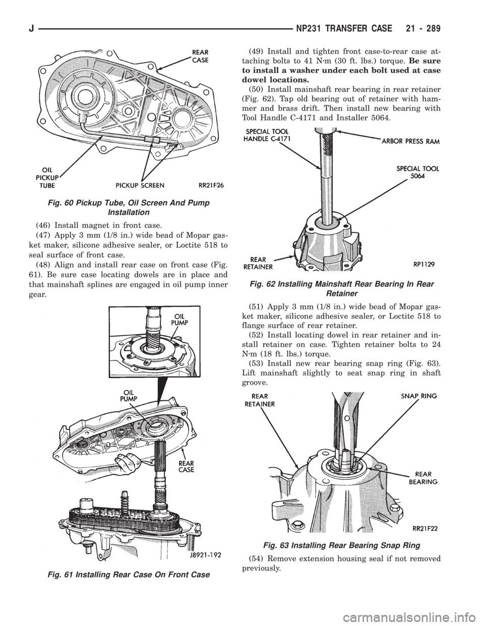
(46) Install magnet in front case.
(47) Apply 3 mm (1/8 in.) wide bead of Mopar gas-
ket maker, silicone adhesive sealer, or Loctite 518 to
seal surface of front case.
(48) Align and install rear case on front case (Fig.
61). Be sure case locating dowels are in place and
that mainshaft splines are engaged in oil pump inner
gear.(49) Install and tighten front case-to-rear case at-
taching bolts to 41 Nzm (30 ft. lbs.) torque.Be sure
to install a washer under each bolt used at case
dowel locations.
(50) Install mainshaft rear bearing in rear retainer
(Fig. 62). Tap old bearing out of retainer with ham-
mer and brass drift. Then install new bearing with
Tool Handle C-4171 and Installer 5064.
(51) Apply 3 mm (1/8 in.) wide bead of Mopar gas-
ket maker, silicone adhesive sealer, or Loctite 518 to
flange surface of rear retainer.
(52) Install locating dowel in rear retainer and in-
stall retainer on case. Tighten retainer bolts to 24
Nzm (18 ft. lbs.) torque.
(53) Install new rear bearing snap ring (Fig. 63).
Lift mainshaft slightly to seat snap ring in shaft
groove.
(54) Remove extension housing seal if not removed
previously.
Fig. 60 Pickup Tube, Oil Screen And Pump
Installation
Fig. 61 Installing Rear Case On Front Case
Fig. 62 Installing Mainshaft Rear Bearing In Rear
Retainer
Fig. 63 Installing Rear Bearing Snap Ring
JNP231 TRANSFER CASE 21 - 289
Page 1401 of 1784
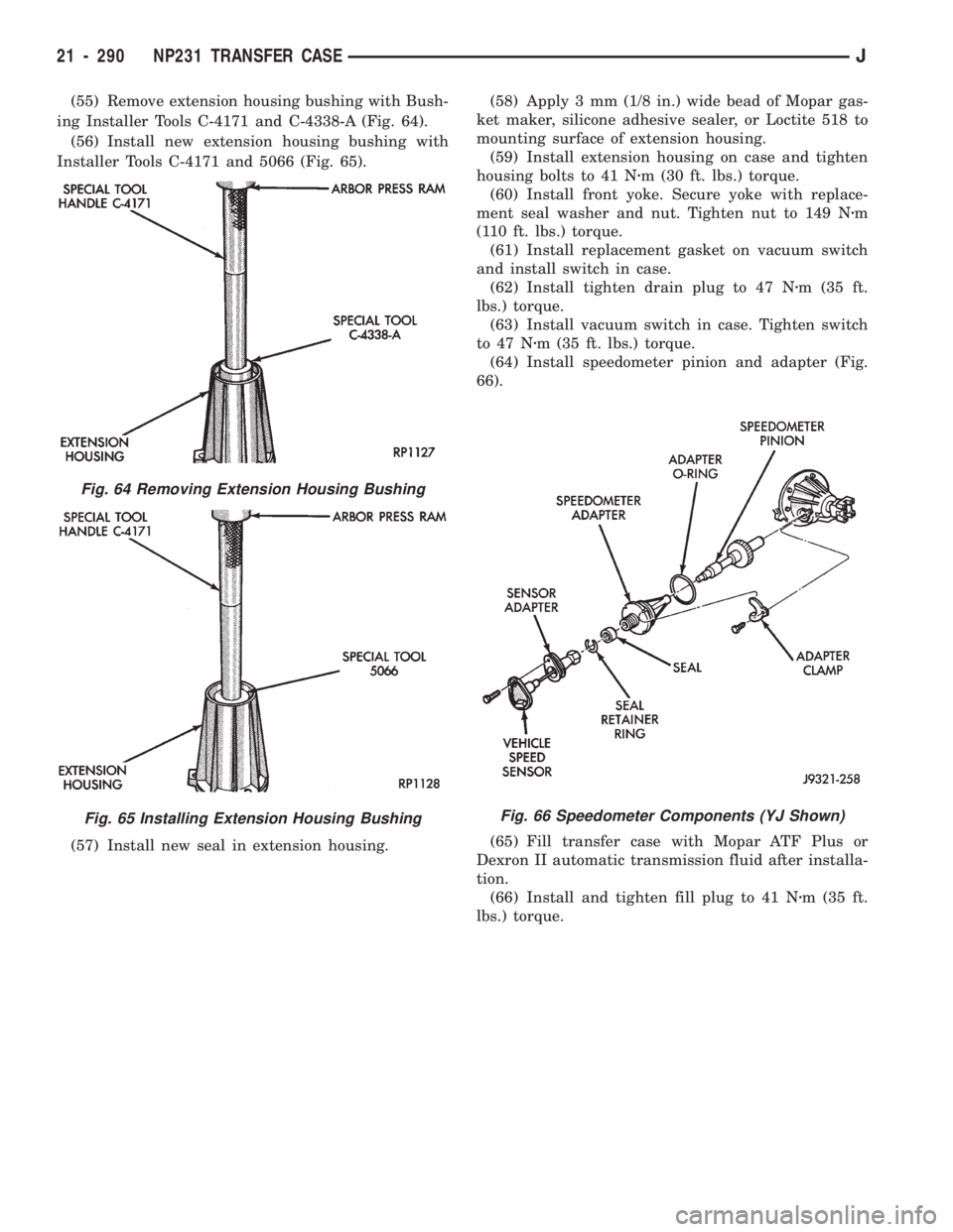
(55) Remove extension housing bushing with Bush-
ing Installer Tools C-4171 and C-4338-A (Fig. 64).
(56) Install new extension housing bushing with
Installer Tools C-4171 and 5066 (Fig. 65).
(57) Install new seal in extension housing.(58) Apply 3 mm (1/8 in.) wide bead of Mopar gas-
ket maker, silicone adhesive sealer, or Loctite 518 to
mounting surface of extension housing.
(59) Install extension housing on case and tighten
housing bolts to 41 Nzm (30 ft. lbs.) torque.
(60) Install front yoke. Secure yoke with replace-
ment seal washer and nut. Tighten nut to 149 Nzm
(110 ft. lbs.) torque.
(61) Install replacement gasket on vacuum switch
and install switch in case.
(62) Install tighten drain plug to 47 Nzm (35 ft.
lbs.) torque.
(63) Install vacuum switch in case. Tighten switch
to 47 Nzm (35 ft. lbs.) torque.
(64) Install speedometer pinion and adapter (Fig.
66).
(65) Fill transfer case with Mopar ATF Plus or
Dexron II automatic transmission fluid after installa-
tion.
(66) Install and tighten fill plug to 41 Nzm (35 ft.
lbs.) torque.
Fig. 64 Removing Extension Housing Bushing
Fig. 65 Installing Extension Housing BushingFig. 66 Speedometer Components (YJ Shown)
21 - 290 NP231 TRANSFER CASEJ