1994 JEEP CHEROKEE torque
[x] Cancel search: torquePage 1280 of 1784
PRESSURE TEST ANALYSIS
If pressures in D and Reverse are higher than
specified, check for the following:
²throttle cable loose, worn, binding or out of adjust-
ment
²throttle valve, downshift plug, throttle cam, or pri-
mary regulator valve are sticking, worn or damaged
If pressures in D and Reverse are lower than spec-
ified, check for following:
²throttle cable loose, worn, binding or out of adjust-
ment
²throttle valve, downshift plug, throttle cam stick-
ing, worn or damaged
²primary regulator valve sticking, worn, or dam-
aged
²oil pump gears or housing worn or damaged
²overdrive clutch worn or damaged
If pressures are low in D range only, check for fol-
lowing:
²forward clutch worn or damaged
²fluid leakage in D range circuit (component seal
and O-rings)
If pressures are low in Reverse only, check for fol-
lowing:
²shift cable and manual valve out of adjustment
²fluid leakage in reverse circuit (component seal
and O-rings)
²direct clutch worn or damaged
²first/reverse brake worn or damaged
TORQUE CONVERTER STALL TEST
Stall testing checks the holding ability of the trans-
mission clutches and brakes and of the torque con-
verter stator overrunning clutch.
(1) Be sure transmission fluid is at normal operat-
ing temperature.
(2) Connect tachometer to engine. Position tachom-
eter so it can be viewed from drivers seat.
(3) Apply parking brakes and block wheels.
(4) Apply and hold service brakes.
(5) Shift transfer case into 2H position. On models
with NP249 transfer case, leave transfer case in 4H
position.
(6) Start engine.
WARNING: DO NOT ALLOW ANYONE TO STAND AT
THE FRONT OR REAR OF THE VEHICLE DURING
THE TEST.
(7) Shift transmission into D range.
(8) Press accelerator pedal to wide open throttle
position and note maximum engine rpm. Stall speed
should be 2100 to 2400 rpm in D range.
CAUTION: Do not maintain wide open throttle for
more than 3-4 seconds at a time.(9) Release throttle and shift transmission into
Neutral. Allow transmission fluid to cool for 15-20
seconds.
(10) Shift transmission into Reverse.
(11) Press accelerator down to wide open throttle
position and note maximum engine rpm. Stall speed
should be 2100-to-2400 rpm in Reverse.
STALL SPEED TEST ANALYSIS
If engine rpm is lower than specified in D and Re-
verse, check for the following:
²engine output/performance insufficient
²stator overrunning clutch in torque converter not
holding if engine speed was 1500 rpm or less.
If stall speed in D range is higher than specified,
check for the following:
²line pressure low
²forward clutch slipping
²No. 2 one-way clutch not holding
²overdrive one-way clutch not holding
If stall speed in Reverse was higher than specified,
check for the following:
²line pressure low
²direct clutch slipping
²first/ reverse brake slipping
²overdrive one-way clutch not holding
If stall speeds were higher than specified in both D
and Reverse, check for the following:
²low fluid level
²line pressure low
²overdrive one-way clutch not holding
TIME LAG TEST
This test checks general condition of the overdrive
clutch, forward clutch, rear clutch and first/reverse
brake. Condition is indicated by the amount of time
required for clutch/brake engagement with the en-
gine at curb idle speed. Engagement time is mea-
sured for D and Reverse positions. A stop watch is
recommended for test accuracy.
TEST PROCEDURE
(1) Check and adjust transmission fluid level if
necessary.
(2) Bring transmission to normal operating tem-
perature.
(3) Apply parking brakes and turn off air condi-
tioning unit.
(4) Shift transfer case into 2H range. On models
with NP249 transfer case, leave transfer case in 4H
range.
(5) Start engine and check curb idle speed. Adjust
speed if necessary. Curb idle must be correct to en-
sure accurate test results.
(6) Shift transmission into Neutral and set stop
watch.
(7) During following test steps, start stop watch as
soon as shift lever reaches D and Reverse ranges.
JAW-4 TRANSMISSION DIAGNOSIS 21 - 169
Page 1285 of 1784
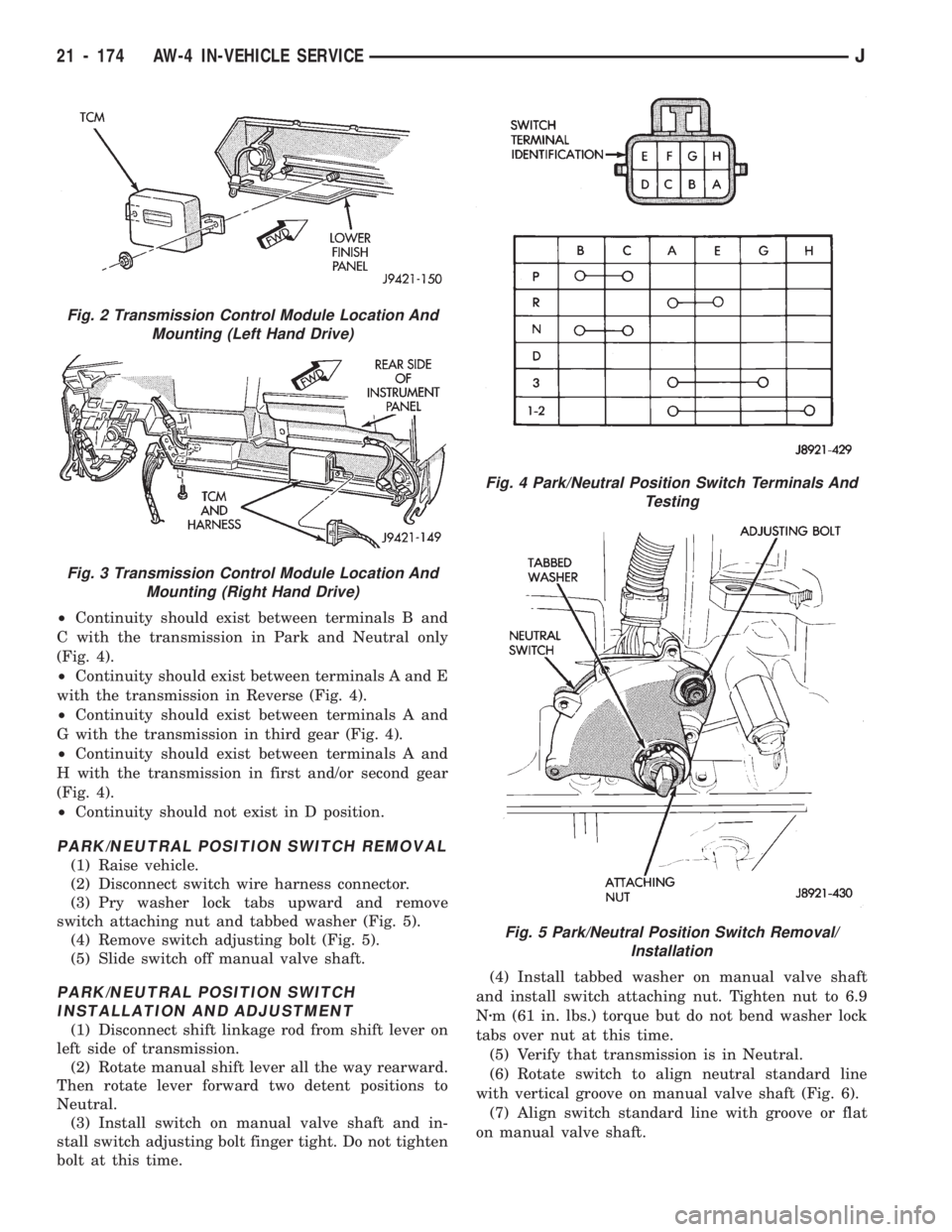
²Continuity should exist between terminals B and
C with the transmission in Park and Neutral only
(Fig. 4).
²Continuity should exist between terminals A and E
with the transmission in Reverse (Fig. 4).
²Continuity should exist between terminals A and
G with the transmission in third gear (Fig. 4).
²Continuity should exist between terminals A and
H with the transmission in first and/or second gear
(Fig. 4).
²Continuity should not exist in D position.
PARK/NEUTRAL POSITION SWITCH REMOVAL
(1) Raise vehicle.
(2) Disconnect switch wire harness connector.
(3) Pry washer lock tabs upward and remove
switch attaching nut and tabbed washer (Fig. 5).
(4) Remove switch adjusting bolt (Fig. 5).
(5) Slide switch off manual valve shaft.
PARK/NEUTRAL POSITION SWITCH
INSTALLATION AND ADJUSTMENT
(1) Disconnect shift linkage rod from shift lever on
left side of transmission.
(2) Rotate manual shift lever all the way rearward.
Then rotate lever forward two detent positions to
Neutral.
(3) Install switch on manual valve shaft and in-
stall switch adjusting bolt finger tight. Do not tighten
bolt at this time.(4) Install tabbed washer on manual valve shaft
and install switch attaching nut. Tighten nut to 6.9
Nzm (61 in. lbs.) torque but do not bend washer lock
tabs over nut at this time.
(5) Verify that transmission is in Neutral.
(6) Rotate switch to align neutral standard line
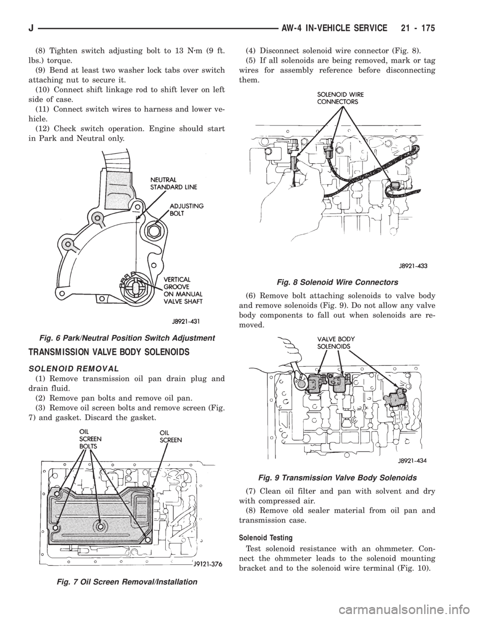
with vertical groove on manual valve shaft (Fig. 6).
(7) Align switch standard line with groove or flat
on manual valve shaft.
Fig. 2 Transmission Control Module Location And
Mounting (Left Hand Drive)
Fig. 3 Transmission Control Module Location And
Mounting (Right Hand Drive)
Fig. 4 Park/Neutral Position Switch Terminals And
Testing
Fig. 5 Park/Neutral Position Switch Removal/
Installation
21 - 174 AW-4 IN-VEHICLE SERVICEJ
Page 1286 of 1784
(8) Tighten switch adjusting bolt to 13 Nzm(9ft.
lbs.) torque.
(9) Bend at least two washer lock tabs over switch
attaching nut to secure it.
(10) Connect shift linkage rod to shift lever on left
side of case.
(11) Connect switch wires to harness and lower ve-
hicle.
(12) Check switch operation. Engine should start
in Park and Neutral only.
TRANSMISSION VALVE BODY SOLENOIDS
SOLENOID REMOVAL
(1) Remove transmission oil pan drain plug and
drain fluid.
(2) Remove pan bolts and remove oil pan.
(3) Remove oil screen bolts and remove screen (Fig.
7) and gasket. Discard the gasket.(4) Disconnect solenoid wire connector (Fig. 8).
(5) If all solenoids are being removed, mark or tag
wires for assembly reference before disconnecting
them.
(6) Remove bolt attaching solenoids to valve body
and remove solenoids (Fig. 9). Do not allow any valve
body components to fall out when solenoids are re-
moved.
(7) Clean oil filter and pan with solvent and dry
with compressed air.
(8) Remove old sealer material from oil pan and
transmission case.
Solenoid Testing
Test solenoid resistance with an ohmmeter. Con-
nect the ohmmeter leads to the solenoid mounting
bracket and to the solenoid wire terminal (Fig. 10).
Fig. 8 Solenoid Wire Connectors
Fig. 9 Transmission Valve Body Solenoids
Fig. 6 Park/Neutral Position Switch Adjustment
Fig. 7 Oil Screen Removal/Installation
JAW-4 IN-VEHICLE SERVICE 21 - 175
Page 1287 of 1784
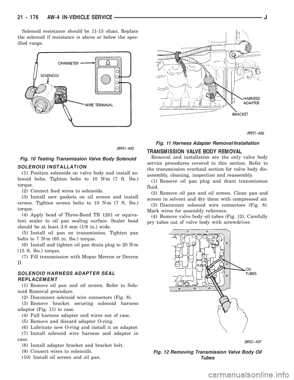
Solenoid resistance should be 11-15 ohms. Replace
the solenoid if resistance is above or below the spec-
ified range.
SOLENOID INSTALLATION
(1) Position solenoids on valve body and install so-
lenoid bolts. Tighten bolts to 10 Nzm (7 ft. lbs.)
torque.
(2) Connect feed wires to solenoids.
(3) Install new gaskets on oil screen and install
screen. Tighten screen bolts to 10 Nzm (7 ft. lbs.)
torque.
(4) Apply bead of Three-Bond TB 1281 or equiva-
lent sealer to oil pan sealing surface. Sealer bead
should be at least 3.0 mm (1/8 in.) wide.
(5) Install oil pan on transmission. Tighten pan
bolts to 7 Nzm (65 in. lbs.) torque.
(6) Install and tighten oil pan drain plug to 20 Nzm
(15 ft. lbs.) torque.
(7) Fill transmission with Mopar Mercon or Dexron
II.
SOLENOID HARNESS ADAPTER SEAL
REPLACEMENT
(1) Remove oil pan and oil screen. Refer to Sole-
noid Removal procedure.
(2) Disconnect solenoid wire connectors (Fig. 8).
(3) Remove bracket securing solenoid harness
adaptor (Fig. 11) to case.
(4) Pull harness adapter and wires out of case.
(5) Remove and discard adapter O-ring.
(6) Lubricate new O-ring and install it on adapter.
(7) Install solenoid wire harness and adapter in
case.
(8) Install adapter bracket and bracket bolt.
(9) Connect wires to solenoids.
(10) Install oil screen and oil pan.
TRANSMISSION VALVE BODY REMOVAL
Removal and installation are the only valve body
service procedures covered in this section. Refer to
the transmission overhaul section for valve body dis-
assembly, cleaning, inspection and reassembly.
(1) Remove oil pan plug and drain transmission
fluid.
(2) Remove oil pan and oil screen. Clean pan and
screen in solvent and dry them with compressed air.
(3) Disconnect solenoid wire connectors (Fig. 8).
Mark wires for assembly reference.
(4) Remove valve body oil tubes (Fig. 12). Carefully
pry tubes out of valve body with screwdriver.
Fig. 11 Harness Adapter Removal/Installation
Fig. 12 Removing Transmission Valve Body Oil
Tubes
Fig. 10 Testing Transmission Valve Body Solenoid
21 - 176 AW-4 IN-VEHICLE SERVICEJ
Page 1288 of 1784
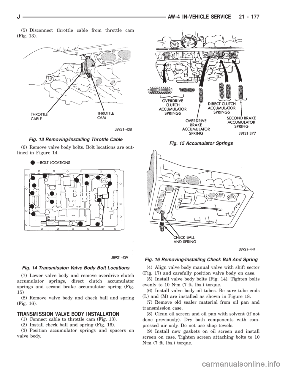
(5) Disconnect throttle cable from throttle cam
(Fig. 13).
(6) Remove valve body bolts. Bolt locations are out-
lined in Figure 14.
(7) Lower valve body and remove overdrive clutch
accumulator springs, direct clutch accumulator
springs and second brake accumulator spring (Fig.
15)
(8) Remove valve body and check ball and spring
(Fig. 16).
TRANSMISSION VALVE BODY INSTALLATION
(1) Connect cable to throttle cam (Fig. 13).
(2) Install check ball and spring (Fig. 16).
(3) Position accumulator springs and spacers on
valve body.(4) Align valve body manual valve with shift sector
(Fig. 17) and carefully position valve body on case.
(5) Install valve body bolts (Fig. 14). Tighten bolts
evenly to 10 Nzm (7 ft. lbs.) torque.
(6) Install valve body oil tubes. Be sure tube ends
(L) and (M) are installed as shown in Figure 18.
(7) Remove old sealer material from oil pan and
transmission case.
(8) Clean oil screen and oil pan with solvent (if not
done previously). Dry both components with com-
pressed air only. Do not use shop towels.
(9) Install new gaskets on oil screen and install
screen on case. Tighten screen attaching bolts to 10
Nzm (7 ft. lbs.) torque.
Fig. 13 Removing/Installing Throttle Cable
Fig. 14 Transmission Valve Body Bolt Locations
Fig. 15 Accumulator Springs
Fig. 16 Removing/Installing Check Ball And Spring
JAW-4 IN-VEHICLE SERVICE 21 - 177
Page 1289 of 1784
(10) Apply bead of Mopar or Loctite 599 sealer to
sealing surface of oil pan. Sealer bead should be at
least 3 mm (1/8 in.) wide. Then install oil pan and
tighten pan bolts to 7.4 Nzm (65 in. lbs.) torque.
(11) Install new gasket on oil pan drain plug and
install plug in pan. Tighten plug to 20 Nzm (15 ft.
lbs.) torque.
(12) Fill transmission with Mopar MerconŸ fluid.
MANUAL VALVE SHAFT SEAL REPLACEMENT
(1) Remove park/neutral position switch and dis-
connect transmission shift lever.
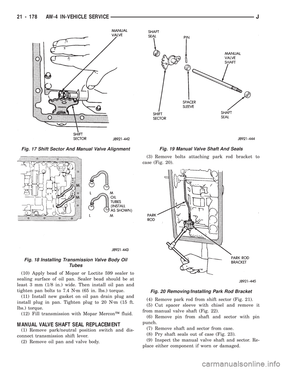
(2) Remove oil pan and valve body.(3) Remove bolts attaching park rod bracket to
case (Fig. 20).
(4) Remove park rod from shift sector (Fig. 21).
(5) Cut spacer sleeve with chisel and remove it
from manual valve shaft (Fig. 22).
(6) Remove pin from shaft and sector with pin
punch.
(7) Remove shaft and sector from case.
(8) Pry shaft seals out of case (Fig. 23).
(9) Inspect the manual valve shaft and sector. Re-
place either component if worn or damaged.
Fig. 19 Manual Valve Shaft And Seals
Fig. 20 Removing/Installing Park Rod Bracket
Fig. 17 Shift Sector And Manual Valve Alignment
Fig. 18 Installing Transmission Valve Body Oil
Tubes
21 - 178 AW-4 IN-VEHICLE SERVICEJ
Page 1290 of 1784
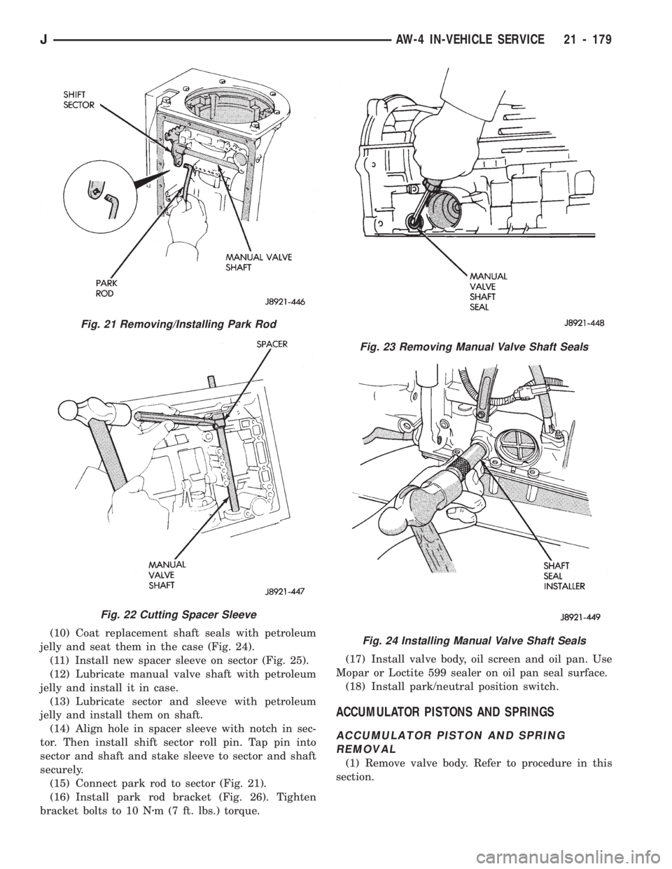
(10) Coat replacement shaft seals with petroleum
jelly and seat them in the case (Fig. 24).
(11) Install new spacer sleeve on sector (Fig. 25).
(12) Lubricate manual valve shaft with petroleum
jelly and install it in case.
(13) Lubricate sector and sleeve with petroleum
jelly and install them on shaft.
(14) Align hole in spacer sleeve with notch in sec-
tor. Then install shift sector roll pin. Tap pin into
sector and shaft and stake sleeve to sector and shaft
securely.
(15) Connect park rod to sector (Fig. 21).
(16) Install park rod bracket (Fig. 26). Tighten
bracket bolts to 10 Nzm (7 ft. lbs.) torque.(17) Install valve body, oil screen and oil pan. Use
Mopar or Loctite 599 sealer on oil pan seal surface.
(18) Install park/neutral position switch.
ACCUMULATOR PISTONS AND SPRINGS
ACCUMULATOR PISTON AND SPRING
REMOVAL
(1) Remove valve body. Refer to procedure in this
section.
Fig. 23 Removing Manual Valve Shaft Seals
Fig. 24 Installing Manual Valve Shaft Seals
Fig. 21 Removing/Installing Park Rod
Fig. 22 Cutting Spacer Sleeve
JAW-4 IN-VEHICLE SERVICE 21 - 179
Page 1293 of 1784
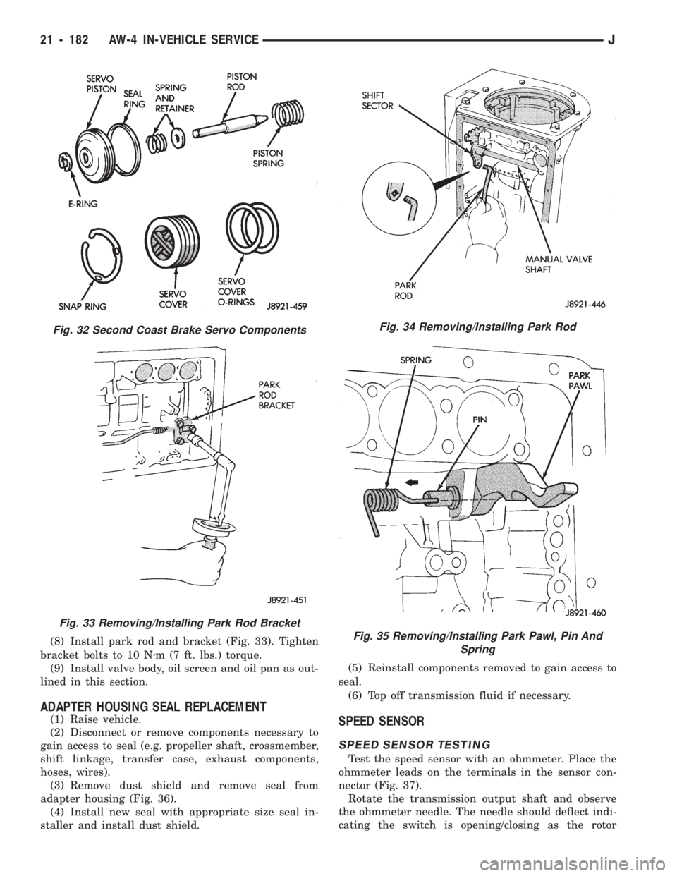
(8) Install park rod and bracket (Fig. 33). Tighten
bracket bolts to 10 Nzm (7 ft. lbs.) torque.
(9) Install valve body, oil screen and oil pan as out-
lined in this section.
ADAPTER HOUSING SEAL REPLACEMENT
(1) Raise vehicle.
(2) Disconnect or remove components necessary to
gain access to seal (e.g. propeller shaft, crossmember,
shift linkage, transfer case, exhaust components,
hoses, wires).
(3) Remove dust shield and remove seal from
adapter housing (Fig. 36).
(4) Install new seal with appropriate size seal in-
staller and install dust shield.(5) Reinstall components removed to gain access to
seal.
(6) Top off transmission fluid if necessary.SPEED SENSOR
SPEED SENSOR TESTING
Test the speed sensor with an ohmmeter. Place the
ohmmeter leads on the terminals in the sensor con-
nector (Fig. 37).
Rotate the transmission output shaft and observe
the ohmmeter needle. The needle should deflect indi-
cating the switch is opening/closing as the rotor
Fig. 34 Removing/Installing Park Rod
Fig. 35 Removing/Installing Park Pawl, Pin And
Spring
Fig. 32 Second Coast Brake Servo Components
Fig. 33 Removing/Installing Park Rod Bracket
21 - 182 AW-4 IN-VEHICLE SERVICEJ