Page 1357 of 1784
(8) Press regulator valve sleeve into bore and in-
stall retainer (Fig. 5 and 6). Be sure retainer is posi-
tioned in sleeve lugs as shown.
(9) Install 1-2 shift valve, spring and plug (Fig. 4).
Then press valve assembly into bore and install re-
tainer.
(10) Install replacement O-rings on solenoids and
install solenoids on valve body. Tighten solenoid at-
taching bolts to 10 Nzm (7 ft-lbs) torque.
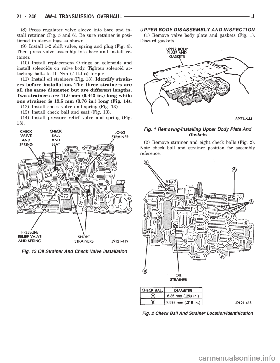
(11) Install oil strainers (Fig. 13).Identify strain-
ers before installation. The three strainers are
all the same diameter but are different lengths.
Two strainers are 11.0 mm (0.443 in.) long while
one strainer is 19.5 mm (0.76 in.) long (Fig. 14).
(12) Install check valve and spring (Fig. 13).
(13) Install check ball and seat (Fig. 13).
(14) Install pressure relief valve and spring (Fig.
13).UPPER BODY DISASSEMBLY AND INSPECTION
(1) Remove valve body plate and gaskets (Fig. 1).
Discard gaskets.
(2) Remove strainer and eight check balls (Fig. 2).
Note check ball and strainer position for assembly
reference.
Fig. 1 Removing/Installing Upper Body Plate And
Gaskets
Fig. 2 Check Ball And Strainer Location/Identification
Fig. 13 Oil Strainer And Check Valve Installation
21 - 246 AW-4 TRANSMISSION OVERHAULJ
Page 1363 of 1784
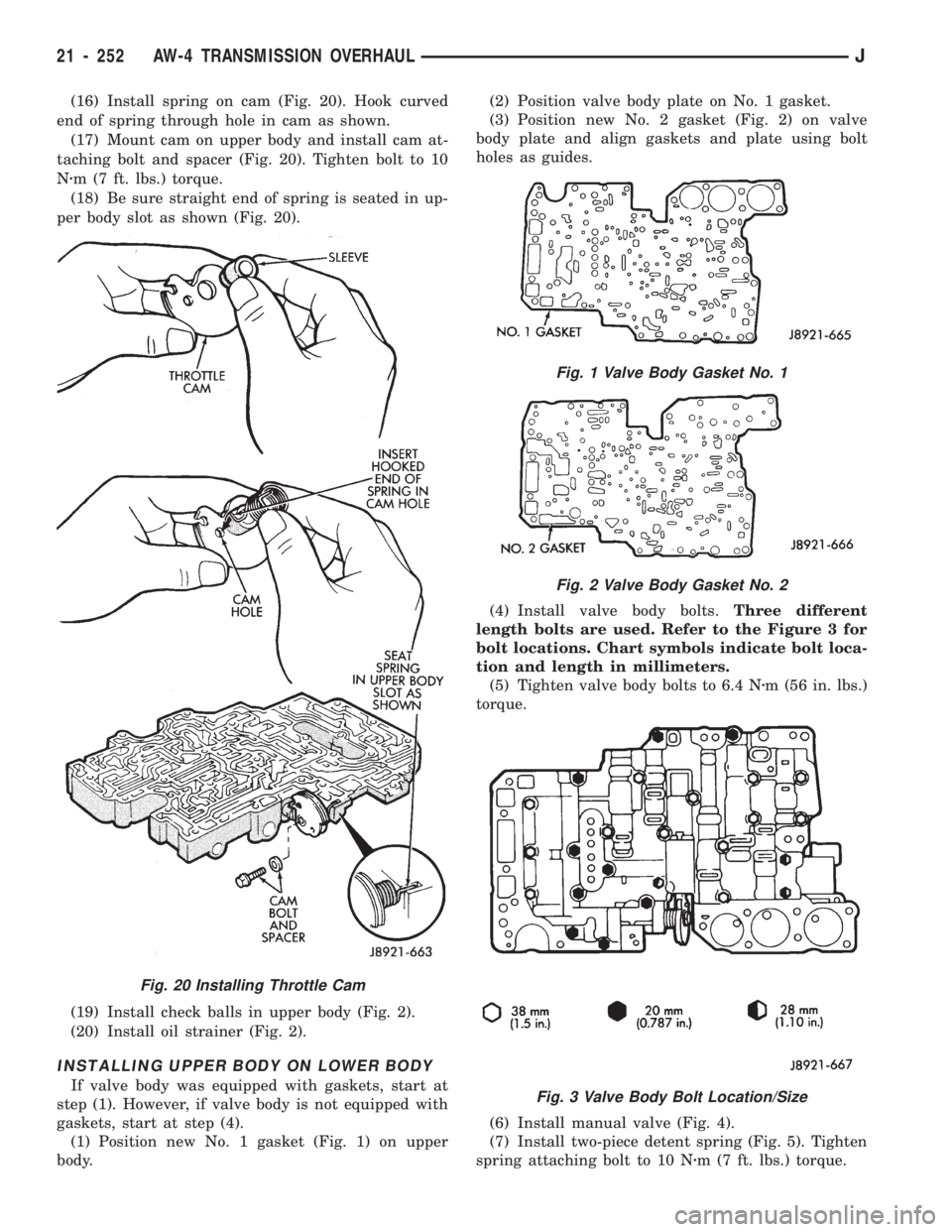
(16) Install spring on cam (Fig. 20). Hook curved
end of spring through hole in cam as shown.
(17) Mount cam on upper body and install cam at-
taching bolt and spacer (Fig. 20). Tighten bolt to 10
Nzm (7 ft. lbs.) torque.
(18) Be sure straight end of spring is seated in up-
per body slot as shown (Fig. 20).
(19) Install check balls in upper body (Fig. 2).
(20) Install oil strainer (Fig. 2).
INSTALLING UPPER BODY ON LOWER BODY
If valve body was equipped with gaskets, start at
step (1). However, if valve body is not equipped with
gaskets, start at step (4).
(1) Position new No. 1 gasket (Fig. 1) on upper
body.(2) Position valve body plate on No. 1 gasket.
(3) Position new No. 2 gasket (Fig. 2) on valve
body plate and align gaskets and plate using bolt
holes as guides.
(4) Install valve body bolts.Three different
length bolts are used. Refer to the Figure 3 for
bolt locations. Chart symbols indicate bolt loca-
tion and length in millimeters.
(5) Tighten valve body bolts to 6.4 Nzm (56 in. lbs.)
torque.
(6) Install manual valve (Fig. 4).
(7) Install two-piece detent spring (Fig. 5). Tighten
spring attaching bolt to 10 Nzm (7 ft. lbs.) torque.
Fig. 20 Installing Throttle Cam
Fig. 1 Valve Body Gasket No. 1
Fig. 2 Valve Body Gasket No. 2
Fig. 3 Valve Body Bolt Location/Size
21 - 252 AW-4 TRANSMISSION OVERHAULJ
Page 1368 of 1784
(12) Install second brake drum gasket with Installer
Tool 7544 (Fig. 9). Gasket depth is 43.7 mm (1.720 in.).
(13) Install park lock pawl, spring and pin (Fig.
10).
(14) Connect park lock rod to manual valve shift
sector (Fig. 11).
(15) Position park lock rod bracket on case and
tighten bracket attaching bolts to 10 Nzm (7 ft. lbs.)
torque (Fig. 12).
(16) Verify park lock operation. Move shift sector
to Park position. Park pawl should be firmly engaged
(locked) in planetary ring gear (Fig. 13).
Fig. 7 Checking First-Reverse Brake Pack Clearance
Fig. 8 Installing Second Brake piston Sleeve
Fig. 9 Installing Second Brake Drum Gasket
Fig. 10 Installing Park Lock Pin, Spring And Pawl
Fig. 11 Installing Park Lock Rod
JAW-4 TRANSMISSION OVERHAUL 21 - 257
Page 1374 of 1784
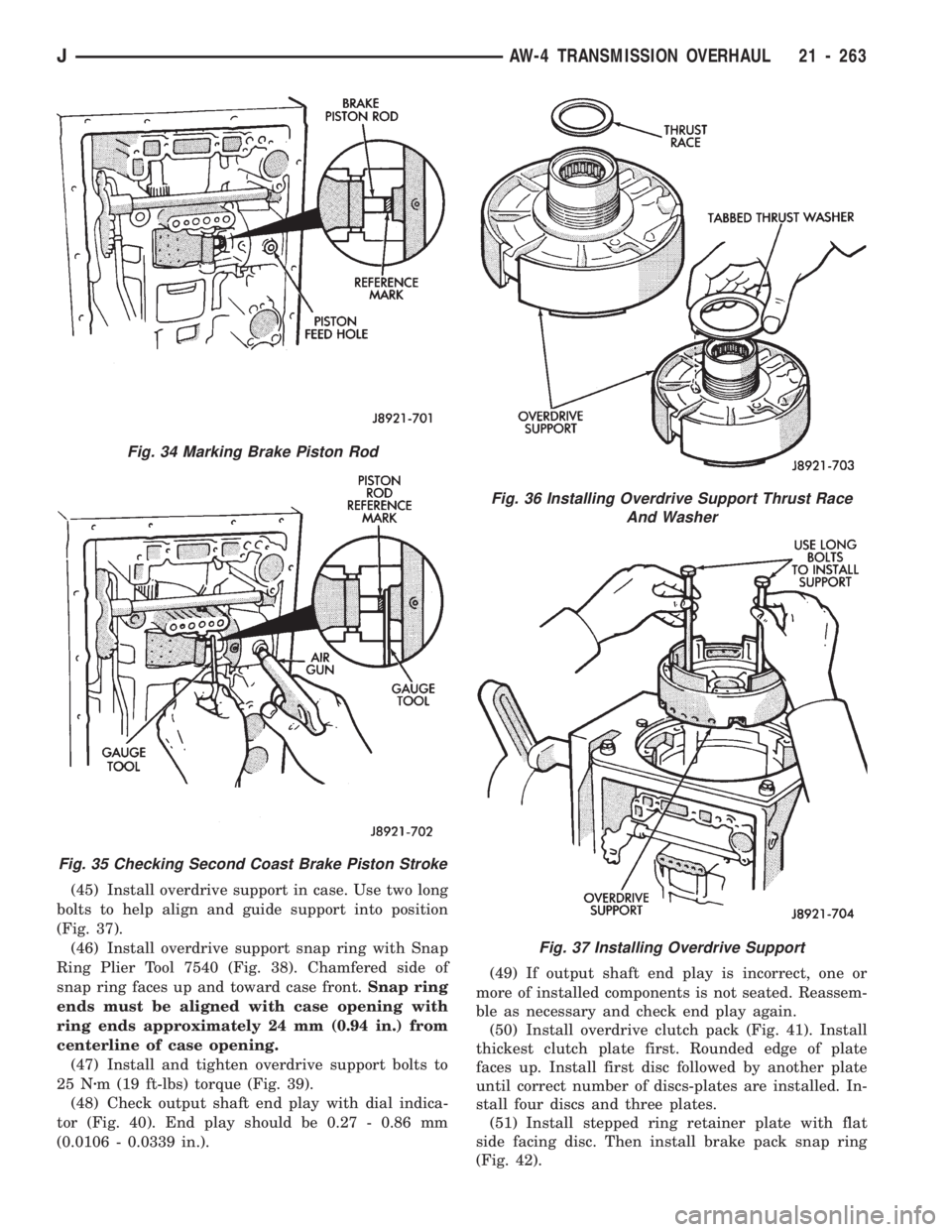
(45) Install overdrive support in case. Use two long
bolts to help align and guide support into position
(Fig. 37).
(46) Install overdrive support snap ring with Snap
Ring Plier Tool 7540 (Fig. 38). Chamfered side of
snap ring faces up and toward case front.Snap ring
ends must be aligned with case opening with
ring ends approximately 24 mm (0.94 in.) from
centerline of case opening.
(47) Install and tighten overdrive support bolts to
25 Nzm (19 ft-lbs) torque (Fig. 39).
(48) Check output shaft end play with dial indica-
tor (Fig. 40). End play should be 0.27 - 0.86 mm
(0.0106 - 0.0339 in.).(49) If output shaft end play is incorrect, one or
more of installed components is not seated. Reassem-
ble as necessary and check end play again.
(50) Install overdrive clutch pack (Fig. 41). Install
thickest clutch plate first. Rounded edge of plate
faces up. Install first disc followed by another plate
until correct number of discs-plates are installed. In-
stall four discs and three plates.
(51) Install stepped ring retainer plate with flat
side facing disc. Then install brake pack snap ring
(Fig. 42).
Fig. 36 Installing Overdrive Support Thrust Race
And Washer
Fig. 37 Installing Overdrive Support
Fig. 34 Marking Brake Piston Rod
Fig. 35 Checking Second Coast Brake Piston Stroke
JAW-4 TRANSMISSION OVERHAUL 21 - 263
Page 1378 of 1784
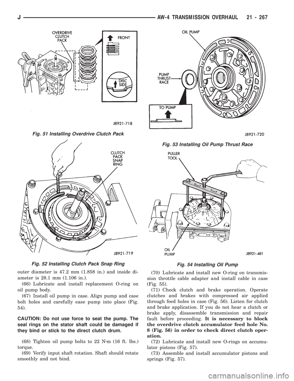
outer diameter is 47.2 mm (1.858 in.) and inside di-
ameter is 28.1 mm (1.106 in.).
(66) Lubricate and install replacement O-ring on
oil pump body.
(67) Install oil pump in case. Align pump and case
bolt holes and carefully ease pump into place (Fig.
54).
CAUTION: Do not use force to seat the pump. The
seal rings on the stator shaft could be damaged if
they bind or stick to the direct clutch drum.
(68) Tighten oil pump bolts to 22 Nzm (16 ft. lbs.)
torque.
(69) Verify input shaft rotation. Shaft should rotate
smoothly and not bind.(70) Lubricate and install new O-ring on transmis-
sion throttle cable adapter and install cable in case
(Fig. 55).
(71) Check clutch and brake operation. Operate
clutches and brakes with compressed air applied
through feed holes in case (Fig. 56). Listen for clutch
and brake application. If you do not hear a clutch or
brake apply, disassemble transmission and repair
fault before proceeding.It is necessary to block
the overdrive clutch accumulator feed hole No.
8 (Fig. 56) in order to check direct clutch oper-
ation.
(72) Lubricate and install new O-rings on accumu-
lator pistons (Fig. 57).
(73) Assemble and install accumulator pistons and
springs (Fig. 57).
Fig. 53 Installing Oil Pump Thrust Race
Fig. 54 Installing Oil Pump
Fig. 51 Installing Overdrive Clutch Pack
Fig. 52 Installing Clutch Pack Snap Ring
JAW-4 TRANSMISSION OVERHAUL 21 - 267
Page 1379 of 1784
(74) Install new check ball body and spring (Fig.
58).
(75) Position valve body on case (Fig. 59).
(76) Install detent spring (Fig. 59).
(77) Align manual valve, detent spring and shift
sector (Fig. 59).
(78) Connect transmission throttle cable to throttle
valve cam (Fig. 60).
(79) Install and tighten valve body-to-case bolts to
10 Nzm (7 ft. lbs.) torque.(80) Connect valve body solenoid wires to solenoids
(Fig. 61).
(81) Install new O-ring on solenoid harness
adapter and secure adapter to case.
Fig. 57 Accumulator Piston And Spring Installation
Fig. 58 Installing Check Ball Body And Spring
Fig. 55 Installing Transmission Throttle Cable
Fig. 56 Clutch And Brake Feed Hole Locations
21 - 268 AW-4 TRANSMISSION OVERHAULJ
Page 1380 of 1784
(82) Install valve body oil tubes (Fig. 62). Tap
tubes into place with a plastic mallet. Be sure the
flanged tube ends and straight tube ends are in-
stalled as shown.
(83) Install new gaskets on oil screen and install
screen on valve body. Tighten screen bolts to 10 Nzm
(7 ft. lbs.) torque.
(84) Install magnet in oil pan. Be sure magnet
does not interfere with valve body oil tubes.
(85) Apply Mopar or Loctite 599 to sealing surface
of oil pan. Sealer bead should be at least 3 mm (1/8
in.) wide. Install pan on case and tighten pan bolts to
7Nzm (65 in. lbs.) torque.
(86) Install transmission speed sensor rotor and
key on output shaft (Fig. 63).
Fig. 63 Installing Transmission Speed Sensor Rotor
And Key
Fig. 61 Connecting Valve Body Solenoid Wires
Fig. 62 Installing Valve Body Oil Tubes
Fig. 59 Aligning Manual Valve, Shift Sector And
Detent Spring
Fig. 60 Connecting Transmission Throttle Cable
JAW-4 TRANSMISSION OVERHAUL 21 - 269
Page 1381 of 1784
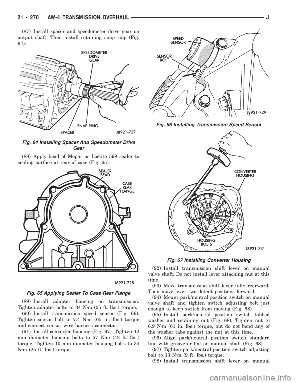
(87) Install spacer and speedometer drive gear on
output shaft. Then install retaining snap ring (Fig.
64).
(88) Apply bead of Mopar or Loctite 599 sealer to
sealing surface at rear of case (Fig. 65).
(89) Install adapter housing on transmission.
Tighten adapter bolts to 34 Nzm (25 ft. lbs.) torque.
(90) Install transmission speed sensor (Fig. 66).
Tighten sensor bolt to 7.4 Nzm (65 in. lbs.) torque
and connect sensor wire harness connector.
(91) Install converter housing (Fig. 67). Tighten 12
mm diameter housing bolts to 57 Nzm (42 ft. lbs.)
torque. Tighten 10 mm diameter housing bolts to 34
Nzm (25 ft. lbs.) torque.(92) Install transmission shift lever on manual
valve shaft. Do not install lever attaching nut at this
time.
(93) Move transmission shift lever fully rearward.
Then move lever two detent positions forward.
(94) Mount park/neutral position switch on manual
valve shaft and tighten switch adjusting bolt just
enough to keep switch from moving (Fig. 68).
(95) Install park/neutral position switch tabbed
washer and retaining nut (Fig. 68). Tighten nut to
6.9 Nzm (61 in. lbs.) torque, but do not bend any of
the washer tabs against the nut at this time.
(96) Align park/neutral position switch standard
line with groove or flat on manual shaft (Fig. 68).
(97) Tighten park/neutral position switch adjusting
bolt to 13 Nzm (9 ft. lbs.) torque.
(98) Install transmission shift lever on manual
Fig. 66 Installing Transmission Speed Sensor
Fig. 67 Installing Converter Housing
Fig. 64 Installing Spacer And Speedometer Drive
Gear
Fig. 65 Applying Sealer To Case Rear Flange
21 - 270 AW-4 TRANSMISSION OVERHAULJ