1994 JEEP CHEROKEE torque
[x] Cancel search: torquePage 1221 of 1784
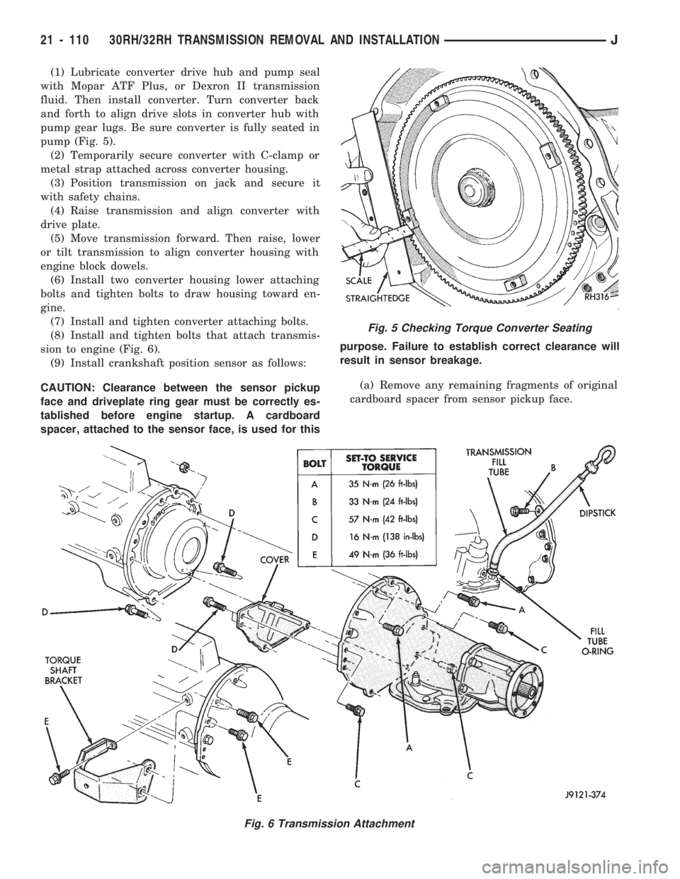
(1) Lubricate converter drive hub and pump seal
with Mopar ATF Plus, or Dexron II transmission
fluid. Then install converter. Turn converter back
and forth to align drive slots in converter hub with
pump gear lugs. Be sure converter is fully seated in
pump (Fig. 5).
(2) Temporarily secure converter with C-clamp or
metal strap attached across converter housing.
(3) Position transmission on jack and secure it
with safety chains.
(4) Raise transmission and align converter with
drive plate.
(5) Move transmission forward. Then raise, lower
or tilt transmission to align converter housing with
engine block dowels.
(6) Install two converter housing lower attaching
bolts and tighten bolts to draw housing toward en-
gine.
(7) Install and tighten converter attaching bolts.
(8) Install and tighten bolts that attach transmis-
sion to engine (Fig. 6).
(9) Install crankshaft position sensor as follows:
CAUTION: Clearance between the sensor pickup
face and driveplate ring gear must be correctly es-
tablished before engine startup. A cardboard
spacer, attached to the sensor face, is used for thispurpose. Failure to establish correct clearance will
result in sensor breakage.
(a) Remove any remaining fragments of original
cardboard spacer from sensor pickup face.
Fig. 5 Checking Torque Converter Seating
Fig. 6 Transmission Attachment
21 - 110 30RH/32RH TRANSMISSION REMOVAL AND INSTALLATIONJ
Page 1222 of 1784
(b) Align and install new spacer on sensor
pickup face. Spacer has adhesive backing so it will
adhere to sensor face.
(c) Insert sensor into housing until it just
touches ring gear teeth. Then install and tighten
sensor attaching bolt. Correct clearance is estab-
lished when spacer is peeled off by ring gear dur-
ing engine startup.
(10) Install transmission fill tube and O-ring (Fig.
6).
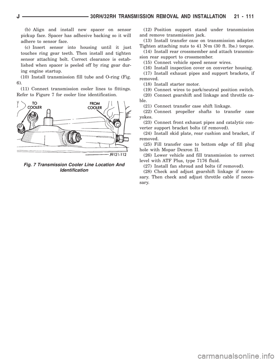
(11) Connect transmission cooler lines to fittings.
Refer to Figure 7 for cooler line identification.(12) Position support stand under transmission
and remove transmission jack.
(13) Install transfer case on transmission adapter.
Tighten attaching nuts to 41 Nzm (30 ft. lbs.) torque.
(14) Install rear crossmember and attach transmis-
sion rear support to crossmember.
(15) Connect vehicle speed sensor wires.
(16) Install inspection cover on converter housing.
(17) Install exhaust pipes and support brackets, if
removed.
(18) Install starter motor.
(19) Connect wires to park/neutral position switch.
(20) Connect gearshift and linkage and throttle ca-
ble.
(21) Connect transfer case shift linkage.
(22) Connect propeller shafts to transfer case
yokes.
(23) Connect front exhaust pipes and catalytic con-
verter support bracket bolts (if removed).
(24) Install skid plate, rear cushion and bracket, if
removed.
(25) Fill transfer case to bottom edge of fill plug
hole with Mopar Dexron II.
(26) Lower vehicle and fill transmission to correct
level with ATF Plus, type 7176 fluid.
(27) Install fan shroud and bolts (if removed).
(28) Check and adjust gearshift linkage if neces-
sary. Then check and adjust throttle cable if neces-
sary.
Fig. 7 Transmission Cooler Line Location And
Identification
J30RH/32RH TRANSMISSION REMOVAL AND INSTALLATION 21 - 111
Page 1234 of 1784
Inspect the pump housing and support components.
Replace the housing or support if the seal ring
grooves or machined surfaces are worn, scored, pit-
ted, or damaged.
Replace the pump gears if pitted, worn chipped, or
damaged. Inspect the thrust washer for wear or dam-
age. Replace the washer if necessary.Note that the
inner gear used in 1993 and later 30RH/32RH oil
pumps has a new design drive lug. The new de-
sign incorporates tapered drive flats instead of
the square lug used previously. The torque con-
verter hub has also been redesigned to accept
the new drive flats. If pump gear replacement is
necessary, be very sure to order and install the
correct style gears.
Inspect the pump and reaction shaft support bush-
ings. Minor bushing wear is acceptable. Replace the
bushings only if scored, or severely worn.
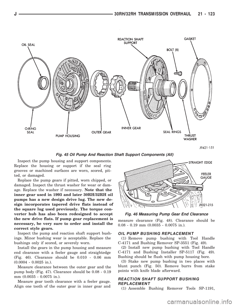
Install the gears in the pump housing and measure
end clearance with a feeler gauge and straightedge
(Fig. 46). Clearance should be 0.010 - 0.06 mm
(0.0004 - 0.0025 in.).
Measure clearance between the outer gear and the
pump body (Fig. 47). Clearance should be 0.08 - 0.19
mm (0.0035 - 0.0075 in.).
Measure gear tooth clearance with a feeler gauge.
Align one tooth of the outer gear in inner gear andmeasure clearance (Fig. 48). Clearance should be
0.08 - 0.19 mm (0.0035 - 0.0075 in.).
OIL PUMP BUSHING REPLACEMENT
(1) Remove pump bushing with Tool Handle
C-4171 and Bushing Remover SP-3551 (Fig. 49).
(2) Install new pump bushing with Tool Handle
C-4171 and Bushing Installer SP-5117 (Fig. 49).
Bushing should be flush with pump housing bore.
(3) Stake new pump bushing in two places with
blunt punch (Fig. 50). Remove burrs from stake
points with knife blade afterward.
REACTION SHAFT SUPPORT BUSHING
REPLACEMENT
(1) Assemble Bushing Remover Tools SP-1191,
Fig. 45 Oil Pump And Reaction Shaft Support Components (All)
Fig. 46 Measuring Pump Gear End Clearance
J30RH/32RH TRANSMISSION OVERHAUL 21 - 123
Page 1236 of 1784
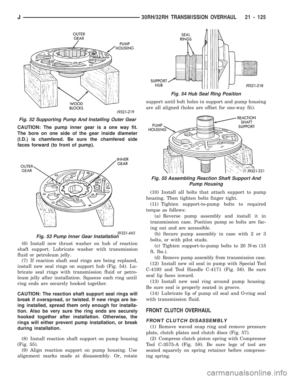
CAUTION: The pump inner gear is a one way fit.
The bore on one side of the gear inside diameter
(I.D.) is chamfered. Be sure the chamfered side
faces forward (to front of pump).
(6) Install new thrust washer on hub of reaction
shaft support. Lubricate washer with transmission
fluid or petroleum jelly.
(7) If reaction shaft seal rings are being replaced,
install new seal rings on support hub (Fig. 54). Lu-
bricate seal rings with transmission fluid or petro-
leum jelly after installation. Squeeze each ring until
ring ends are securely hooked together.
CAUTION: The reaction shaft support seal rings will
break if overspread, or twisted. If new rings are be-
ing installed, spread them only enough for installa-
tion. Also be very sure the ring ends are securely
hooked together after installation. Otherwise, the
rings will either prevent pump installation, or break
during installation.
(8) Install reaction shaft support on pump housing
(Fig. 55).
(9) Align reaction support on pump housing. Use
alignment marks made at disassembly. Or, rotatesupport until bolt holes in support and pump housing
are all aligned (holes are offset for one-way fit).
(10) Install all bolts that attach support to pump
housing. Then tighten bolts finger tight.
(11) Tighten support-to-pump bolts to required
torque as follows:
(a) Reverse pump assembly and install it in
transmission case. Position pump so bolts are fac-
ing out and are accessible.
(b) Secure pump assembly in case with 2 or 3
bolts, or with pilot studs.
(c) Tighten support-to-pump bolts to 20 Nzm (15
ft. lbs.).
(d) Remove pump assembly from transmission case.
(12) Install new oil seal in pump with Special Tool
C-4193 and Tool Handle C-4171 (Fig. 56). Be sure
seal lip faces inward.
(13) Install new seal ring around pump housing.
Be sure seal is properly seated in groove.
(14) Lubricate lip of pump oil seal and O-ring seal
with transmission fluid.
FRONT CLUTCH OVERHAUL
FRONT CLUTCH DISASSEMBLY
(1) Remove waved snap ring and remove pressure
plate, clutch plates and clutch discs (Fig. 57).
(2) Compress clutch piston spring with Compressor
Tool C-3575-A (Fig. 58). Be sure legs of tool are
seated squarely on spring retainer before compress-
ing spring.
Fig. 52 Supporting Pump And Installing Outer Gear
Fig. 53 Pump Inner Gear Installation
Fig. 54 Hub Seal Ring Position
Fig. 55 Assembling Reaction Shaft Support And
Pump Housing
J30RH/32RH TRANSMISSION OVERHAUL 21 - 125
Page 1255 of 1784
VALVE BODY ASSEMBLY AND ADJUSTMENT
CAUTION: Do not force valves or plugs into place
during reassembly. If the valve body bores, valves
and plugs are free of distortion or burrs, the valve
body components should all slide into place easily.
In addition, do not overtighten the transfer plate
and valve body screws during reassembly. Over-
tightening can distort the valve body resulting in
valve sticking, cross leakage and unsatisfactory op-
eration. Tighten valve body screws to recom-
mended torque only.
(1) Lubricate valve body bores, valves and plugs
with ATF Plus, or Dexron IIŸ transmission fluid.
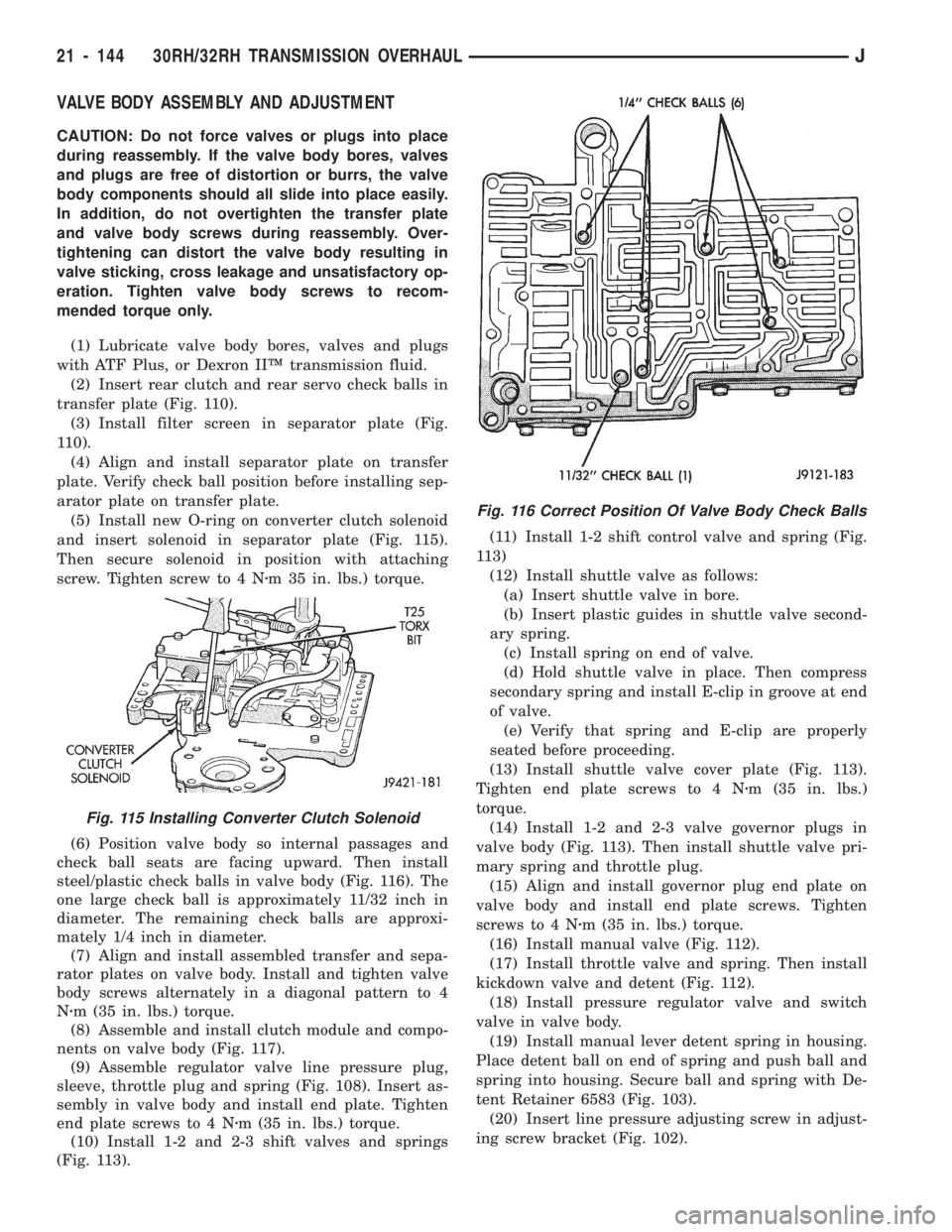
(2) Insert rear clutch and rear servo check balls in
transfer plate (Fig. 110).
(3) Install filter screen in separator plate (Fig.
110).
(4) Align and install separator plate on transfer
plate. Verify check ball position before installing sep-
arator plate on transfer plate.
(5) Install new O-ring on converter clutch solenoid
and insert solenoid in separator plate (Fig. 115).
Then secure solenoid in position with attaching
screw. Tighten screw to 4 Nzm 35 in. lbs.) torque.
(6) Position valve body so internal passages and
check ball seats are facing upward. Then install
steel/plastic check balls in valve body (Fig. 116). The
one large check ball is approximately 11/32 inch in
diameter. The remaining check balls are approxi-
mately 1/4 inch in diameter.
(7) Align and install assembled transfer and sepa-
rator plates on valve body. Install and tighten valve
body screws alternately in a diagonal pattern to 4
Nzm (35 in. lbs.) torque.
(8) Assemble and install clutch module and compo-
nents on valve body (Fig. 117).
(9) Assemble regulator valve line pressure plug,
sleeve, throttle plug and spring (Fig. 108). Insert as-
sembly in valve body and install end plate. Tighten
end plate screws to 4 Nzm (35 in. lbs.) torque.
(10) Install 1-2 and 2-3 shift valves and springs
(Fig. 113).(11) Install 1-2 shift control valve and spring (Fig.
113)
(12) Install shuttle valve as follows:
(a) Insert shuttle valve in bore.
(b) Insert plastic guides in shuttle valve second-
ary spring.
(c) Install spring on end of valve.
(d) Hold shuttle valve in place. Then compress
secondary spring and install E-clip in groove at end
of valve.
(e) Verify that spring and E-clip are properly
seated before proceeding.
(13) Install shuttle valve cover plate (Fig. 113).
Tighten end plate screws to 4 Nzm (35 in. lbs.)
torque.
(14) Install 1-2 and 2-3 valve governor plugs in
valve body (Fig. 113). Then install shuttle valve pri-
mary spring and throttle plug.
(15) Align and install governor plug end plate on
valve body and install end plate screws. Tighten
screws to 4 Nzm (35 in. lbs.) torque.
(16) Install manual valve (Fig. 112).
(17) Install throttle valve and spring. Then install
kickdown valve and detent (Fig. 112).
(18) Install pressure regulator valve and switch
valve in valve body.
(19) Install manual lever detent spring in housing.
Place detent ball on end of spring and push ball and
spring into housing. Secure ball and spring with De-
tent Retainer 6583 (Fig. 103).
(20) Insert line pressure adjusting screw in adjust-
ing screw bracket (Fig. 102).
Fig. 116 Correct Position Of Valve Body Check Balls
Fig. 115 Installing Converter Clutch Solenoid
21 - 144 30RH/32RH TRANSMISSION OVERHAULJ
Page 1256 of 1784
(21) Install spring on end of line pressure regula-
tor valve.
(22) Install switch valve spring on tang at end of
adjusting screw bracket (Fig. 102).
(23) Position adjusting screw bracket on valve
body. Align valve springs and press bracket into
place. Install short, upper bracket screws first and
long bottom screw last. Verify that valve springs and
bracket are properly aligned. Then tighten all three
bracket screws to 4 Nzm (35 in. lbs.) torque.
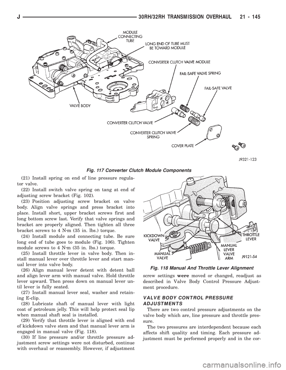
(24) Install module and connecting tube. Be sure
long end of tube goes to module (Fig. 106). Tighten
module screws to 4 Nzm (35 in. lbs.) torque.
(25) Install throttle lever in valve body. Then in-
stall manual lever over throttle lever and start man-
ual lever into valve body.
(26) Align manual lever detent with detent ball
and align lever arm with manual valve. Hold throttle
lever upward. Then press down on manual lever un-
til lever is fully seated.
(27) Install manual lever seal, washer and retain-
ing E-clip.
(28) Lubricate shaft of manual lever with light
coat of petroleum jelly. This will help protect seal lip
when manual shaft seal is installed.
(29) Verify that throttle lever is aligned with end
of kickdown valve stem and that manual lever arm is
engaged in manual valve (Fig. 118).
(30) If line pressure and/or throttle pressure ad-
justment screw settings were not disturbed, continue
with overhaul or reassembly. However, if adjustmentscrew settingsweremoved or changed, readjust as
described in Valve Body Control Pressure Adjust-
ment procedure.
VALVE BODY CONTROL PRESSURE
ADJUSTMENTS
There are two control pressure adjustments on the
valve body which are, line pressure and throttle pres-
sure.
The two pressures are interdependent because each
affects shift quality and timing. Each pressure ad-
justment must be performed properly and in the cor-
Fig. 118 Manual And Throttle Lever Alignment
Fig. 117 Converter Clutch Module Components
J30RH/32RH TRANSMISSION OVERHAUL 21 - 145
Page 1258 of 1784
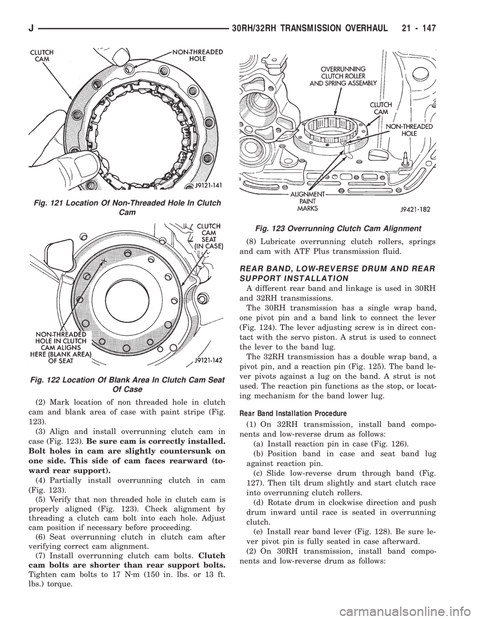
(2) Mark location of non threaded hole in clutch
cam and blank area of case with paint stripe (Fig.
123).
(3) Align and install overrunning clutch cam in
case (Fig. 123).Be sure cam is correctly installed.
Bolt holes in cam are slightly countersunk on
one side. This side of cam faces rearward (to-
ward rear support).
(4) Partially install overrunning clutch in cam
(Fig. 123).
(5) Verify that non threaded hole in clutch cam is
properly aligned (Fig. 123). Check alignment by
threading a clutch cam bolt into each hole. Adjust
cam position if necessary before proceeding.
(6) Seat overrunning clutch in clutch cam after
verifying correct cam alignment.
(7) Install overrunning clutch cam bolts.Clutch
cam bolts are shorter than rear support bolts.
Tighten cam bolts to 17 Nzm (150 in. lbs. or 13 ft.
lbs.) torque.(8) Lubricate overrunning clutch rollers, springs
and cam with ATF Plus transmission fluid.
REAR BAND, LOW-REVERSE DRUM AND REAR
SUPPORT INSTALLATION
A different rear band and linkage is used in 30RH
and 32RH transmissions.
The 30RH transmission has a single wrap band,
one pivot pin and a band link to connect the lever
(Fig. 124). The lever adjusting screw is in direct con-
tact with the servo piston. A strut is used to connect
the lever to the band lug.
The 32RH transmission has a double wrap band, a
pivot pin, and a reaction pin (Fig. 125). The band le-
ver pivots against a lug on the band. A strut is not
used. The reaction pin functions as the stop, or locat-
ing mechanism for the band lower lug.
Rear Band Installation Procedure
(1) On 32RH transmission, install band compo-
nents and low-reverse drum as follows:
(a) Install reaction pin in case (Fig. 126).
(b) Position band in case and seat band lug
against reaction pin.
(c) Slide low-reverse drum through band (Fig.
127). Then tilt drum slightly and start clutch race
into overrunning clutch rollers.
(d) Rotate drum in clockwise direction and push
drum inward until race is seated in overrunning
clutch.
(e) Install rear band lever (Fig. 128). Be sure le-
ver pivot pin is fully seated in case afterward.
(2) On 30RH transmission, install band compo-
nents and low-reverse drum as follows:
Fig. 123 Overrunning Clutch Cam Alignment
Fig. 121 Location Of Non-Threaded Hole In Clutch
Cam
Fig. 122 Location Of Blank Area In Clutch Cam Seat
Of Case
J30RH/32RH TRANSMISSION OVERHAUL 21 - 147
Page 1259 of 1784
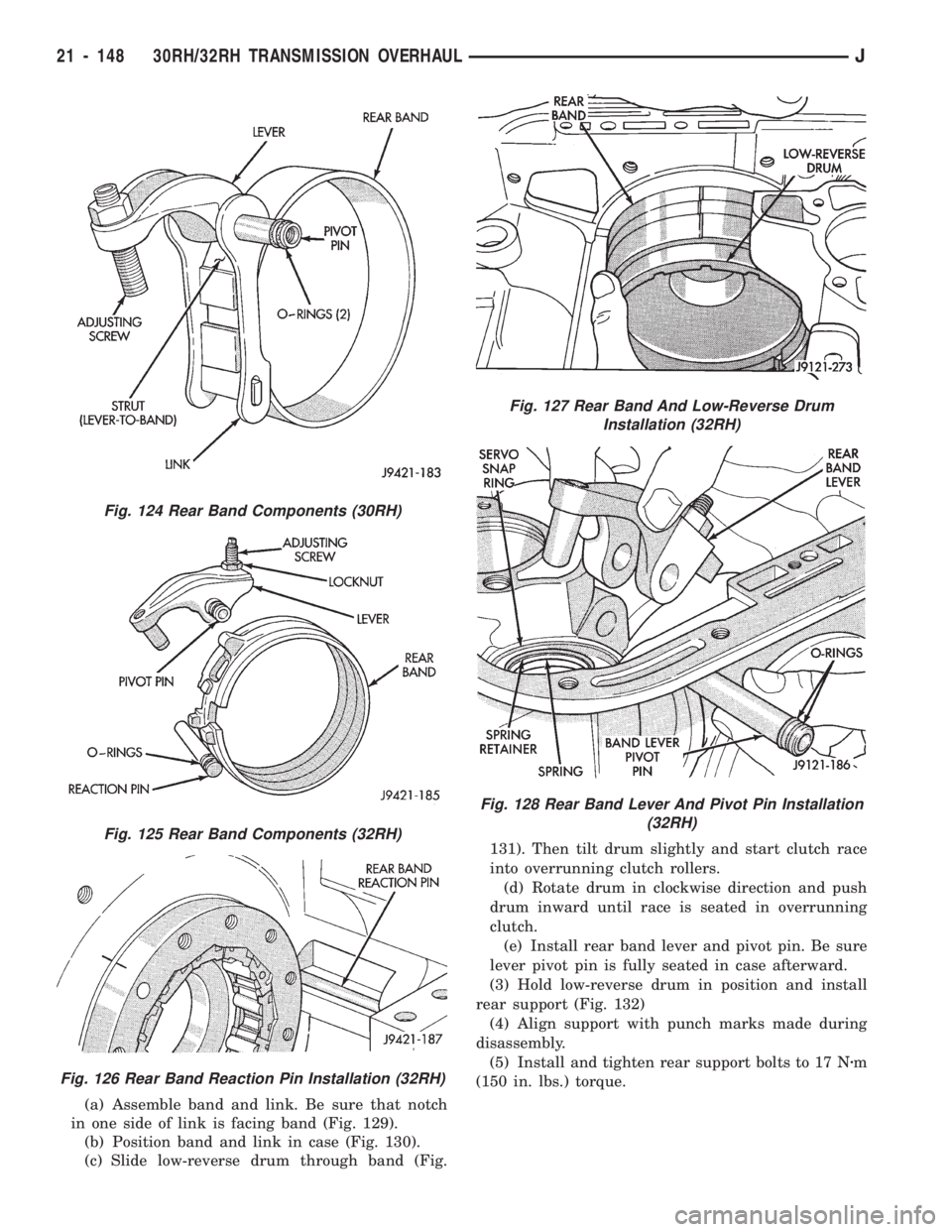
(a) Assemble band and link. Be sure that notch
in one side of link is facing band (Fig. 129).
(b) Position band and link in case (Fig. 130).
(c) Slide low-reverse drum through band (Fig.131). Then tilt drum slightly and start clutch race
into overrunning clutch rollers.
(d) Rotate drum in clockwise direction and push
drum inward until race is seated in overrunning
clutch.
(e) Install rear band lever and pivot pin. Be sure
lever pivot pin is fully seated in case afterward.
(3) Hold low-reverse drum in position and install
rear support (Fig. 132)
(4) Align support with punch marks made during
disassembly.
(5) Install and tighten rear support bolts to 17 Nzm
(150 in. lbs.) torque.
Fig. 124 Rear Band Components (30RH)
Fig. 125 Rear Band Components (32RH)
Fig. 126 Rear Band Reaction Pin Installation (32RH)
Fig. 127 Rear Band And Low-Reverse Drum
Installation (32RH)
Fig. 128 Rear Band Lever And Pivot Pin Installation
(32RH)
21 - 148 30RH/32RH TRANSMISSION OVERHAULJ