1994 JEEP CHEROKEE torque
[x] Cancel search: torquePage 1294 of 1784
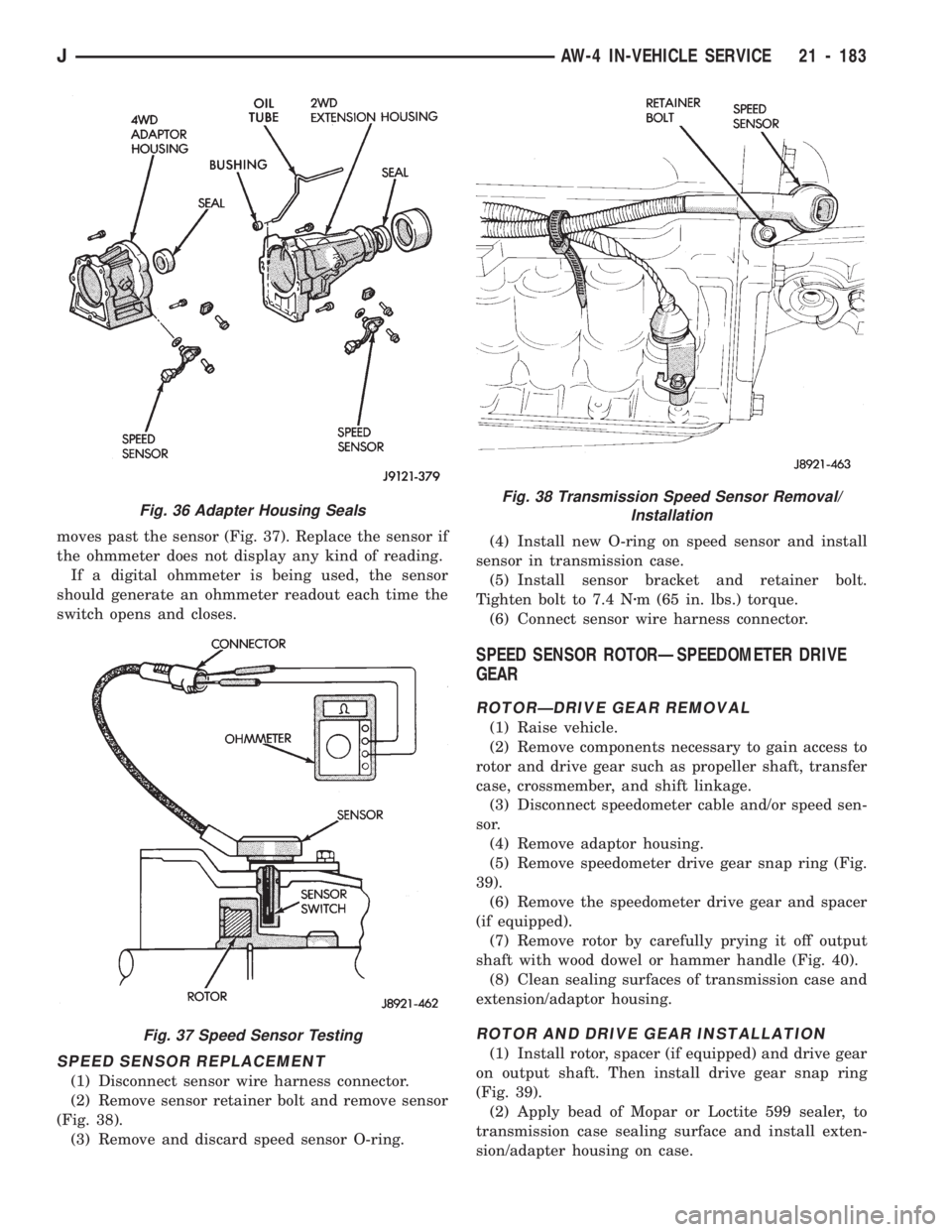
moves past the sensor (Fig. 37). Replace the sensor if
the ohmmeter does not display any kind of reading.
If a digital ohmmeter is being used, the sensor
should generate an ohmmeter readout each time the
switch opens and closes.
SPEED SENSOR REPLACEMENT
(1) Disconnect sensor wire harness connector.
(2) Remove sensor retainer bolt and remove sensor
(Fig. 38).
(3) Remove and discard speed sensor O-ring.(4) Install new O-ring on speed sensor and install
sensor in transmission case.
(5) Install sensor bracket and retainer bolt.
Tighten bolt to 7.4 Nzm (65 in. lbs.) torque.
(6) Connect sensor wire harness connector.
SPEED SENSOR ROTORÐSPEEDOMETER DRIVE
GEAR
ROTORÐDRIVE GEAR REMOVAL
(1) Raise vehicle.
(2) Remove components necessary to gain access to
rotor and drive gear such as propeller shaft, transfer
case, crossmember, and shift linkage.
(3) Disconnect speedometer cable and/or speed sen-
sor.
(4) Remove adaptor housing.
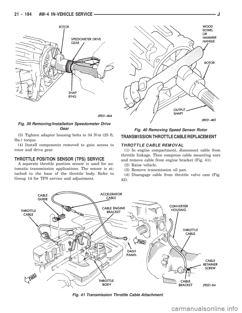
(5) Remove speedometer drive gear snap ring (Fig.
39).
(6) Remove the speedometer drive gear and spacer
(if equipped).
(7) Remove rotor by carefully prying it off output
shaft with wood dowel or hammer handle (Fig. 40).
(8) Clean sealing surfaces of transmission case and
extension/adaptor housing.
ROTOR AND DRIVE GEAR INSTALLATION
(1) Install rotor, spacer (if equipped) and drive gear
on output shaft. Then install drive gear snap ring
(Fig. 39).
(2) Apply bead of Mopar or Loctite 599 sealer, to
transmission case sealing surface and install exten-
sion/adapter housing on case.
Fig. 36 Adapter Housing Seals
Fig. 37 Speed Sensor Testing
Fig. 38 Transmission Speed Sensor Removal/
Installation
JAW-4 IN-VEHICLE SERVICE 21 - 183
Page 1295 of 1784
(3) Tighten adaptor housing bolts to 34 Nzm (25 ft.
lbs.) torque.
(4) Install components removed to gain access to
rotor and drive gear.
THROTTLE POSITION SENSOR (TPS) SERVICE
A separate throttle position sensor is used for au-
tomatic transmission applications. The sensor is at-
tached to the base of the throttle body. Refer to
Group 14 for TPS service and adjustment.
TRANSMISSION THROTTLE CABLE REPLACEMENT
THROTTLE CABLE REMOVAL
(1) In engine compartment, disconnect cable from
throttle linkage. Then compress cable mounting ears
and remove cable from engine bracket (Fig. 41).
(2) Raise vehicle.
(3) Remove transmission oil pan.
(4) Disengage cable from throttle valve cam (Fig.
42).
Fig. 41 Transmission Throttle Cable Attachment
Fig. 40 Removing Speed Sensor Rotor
Fig. 39 Removing/Installation Speedometer Drive
Gear
21 - 184 AW-4 IN-VEHICLE SERVICEJ
Page 1296 of 1784
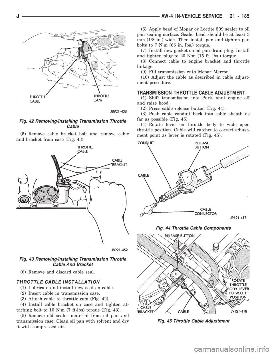
(5) Remove cable bracket bolt and remove cable
and bracket from case (Fig. 43).
(6) Remove and discard cable seal.
THROTTLE CABLE INSTALLATION
(1) Lubricate and install new seal on cable.
(2) Insert cable in transmission case.
(3) Attach cable to throttle cam (Fig. 42).
(4) Install cable bracket on case and tighten at-
taching bolt to 10 Nzm (7 ft-lbs) torque (Fig. 43).
(5) Remove old sealer material from oil pan and
transmission case. Clean oil pan with solvent and dry
it with compressed air.(6) Apply bead of Mopar or Loctite 599 sealer to oil
pan sealing surface. Sealer bead should be at least 3
mm (1/8 in.) wide. Then install pan and tighten pan
bolts to 7 Nzm (65 in. lbs.) torque.
(7) Install new gasket on oil pan drain plug. Install
and tighten plug to 20 Nzm (15 ft. lbs.) torque.
(8) Connect cable to engine bracket and throttle
linkage.
(9) Fill transmission with Mopar Mercon.
(10) Adjust the cable as described in cable adjust-
ment procedure.
TRANSMISSION THROTTLE CABLE ADJUSTMENT
(1) Shift transmission into Park, shut engine off
and raise hood.
(2) Press cable release button (Fig. 44).
(3) Push cable conduit back into cable sheath as
far as possible (Fig. 45).
(4) Rotate lever on throttle body to wide open
throttle position. Cable will ratchet to correct adjust-
ment point as lever is rotated (Fig. 45).
Fig. 42 Removing/Installing Transmission Throttle
Cable
Fig. 43 Removing/Installing Transmission Throttle
Cable And Bracket
Fig. 44 Throttle Cable Components
Fig. 45 Throttle Cable Adjustment
JAW-4 IN-VEHICLE SERVICE 21 - 185
Page 1300 of 1784
AW-4 TRANSMISSION REMOVAL AND INSTALLATION
INDEX
page page
Oil Pump Seal Replacement............... 189
Torque Converter Stator Clutch Inspection..... 189Transmission and Torque Converter Installation . 190
Transmission and Torque Converter Removal . . 189
TRANSMISSION AND TORQUE CONVERTER
REMOVAL
(1) Raise vehicle.
(2) Drain transmission fluid and reinstall oil pan
drain plug.
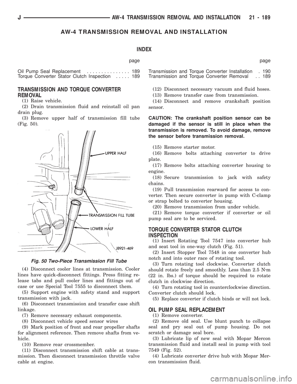
(3) Remove upper half of transmission fill tube
(Fig. 50).
(4) Disconnect cooler lines at transmission. Cooler
lines have quick-disconnect fittings. Press fitting re-
lease tabs and pull cooler lines and fittings out of
case or use Special Tool 7555 to disconnect them.
(5) Support engine with safety stand and support
transmission with jack.
(6) Disconnect transmission and transfer case shift
linkage.
(7) Remove necessary exhaust components.
(8) Disconnect vehicle speed sensor wires
(9) Mark position of front and rear propeller shafts
for alignment reference. Then remove shafts from ve-
hicle.
(10) Remove rear crossmember.
(11) Disconnect transmission shift cable at trans-
mission. Then disconnect transmission throttle valve
cable at engine.(12) Disconnect necessary vacuum and fluid hoses.
(13) Remove transfer case from transmission.
(14) Disconnect and remove crankshaft position
sensor.
CAUTION: The crankshaft position sensor can be
damaged if the sensor is still in place when the
transmission is removed. To avoid damage, remove
the sensor before transmission removal.
(15) Remove starter motor.
(16) Remove bolts attaching converter to drive
plate.
(17) Remove bolts attaching converter housing to
engine.
(18) Secure transmission to jack with safety
chains.
(19) Pull transmission rearward for access to con-
verter. Then secure converter in pump with C-clamp
or strap bolted to converter housing.
(20) Remove transmission from under vehicle.
(21) Remove torque converter if converter or oil
pump seal are to be serviced.
TORQUE CONVERTER STATOR CLUTCH
INSPECTION
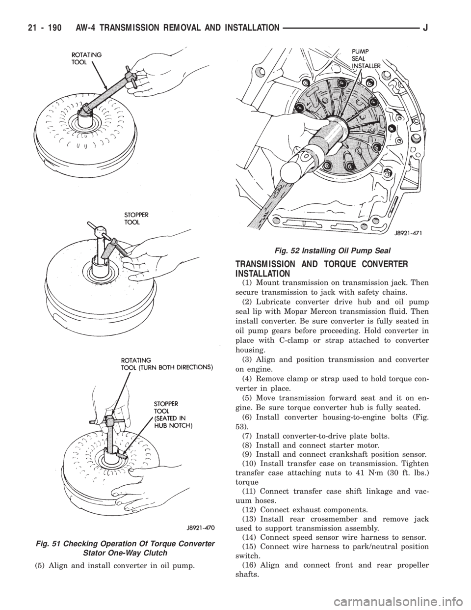
(1) Insert Rotating Tool 7547 into converter hub
and seat tool in one-way clutch (Fig. 51).
(2) Insert Stopper Tool 7548 in one converter hub
notch and into outer race of rotating tool.
(3) Turn rotating tool clockwise. Converter clutch
should rotate freely and smoothly. Less than 2.5 Nzm
(22 in. lbs.) of torque should be required to rotate
clutch in clockwise direction.
(4) Turn rotating tool in counterclockwise direction.
Converter clutch should lock.
(5)
Replace converter if clutch binds or will not lock.
OIL PUMP SEAL REPLACEMENT
(1) Remove converter.
(2) Remove old seal. Use blunt punch to collapse
seal and pry seal out of pump housing. Do not
scratch or damage seal bore.
(3) Lubricate lip of new seal with Mopar Mercon
transmission fluid and install seal in pump with tool
7549 (Fig. 52).
(4) Lubricate converter drive hub with Mopar Mer-
con transmission fluid.
Fig. 50 Two-Piece Transmission Fill Tube
JAW-4 TRANSMISSION REMOVAL AND INSTALLATION 21 - 189
Page 1301 of 1784
(5) Align and install converter in oil pump.
TRANSMISSION AND TORQUE CONVERTER
INSTALLATION
(1) Mount transmission on transmission jack. Then
secure transmission to jack with safety chains.
(2) Lubricate converter drive hub and oil pump
seal lip with Mopar Mercon transmission fluid. Then
install converter. Be sure converter is fully seated in
oil pump gears before proceeding. Hold converter in
place with C-clamp or strap attached to converter
housing.
(3) Align and position transmission and converter
on engine.
(4) Remove clamp or strap used to hold torque con-
verter in place.
(5) Move transmission forward seat and it on en-
gine. Be sure torque converter hub is fully seated.
(6)
Install converter housing-to-engine bolts (Fig.
53).
(7) Install converter-to-drive plate bolts.
(8) Install and connect starter motor.
(9) Install and connect crankshaft position sensor.
(10) Install transfer case on transmission. Tighten
transfer case attaching nuts to 41 Nzm (30 ft. lbs.)
torque
(11) Connect transfer case shift linkage and vac-
uum hoses.
(12) Connect exhaust components.
(13) Install rear crossmember and remove jack
used to support transmission assembly.
(14) Connect speed sensor wire harness to sensor.
(15) Connect wire harness to park/neutral position
switch.
(16) Align and connect front and rear propeller
shafts.
Fig. 51 Checking Operation Of Torque Converter
Stator One-Way Clutch
Fig. 52 Installing Oil Pump Seal
21 - 190 AW-4 TRANSMISSION REMOVAL AND INSTALLATIONJ
Page 1303 of 1784
AW-4 TRANSMISSION OVERHAUL
INDEX
page page
Cleaning and Inspection................... 76
Direct Clutch Overhaul................... 219
First-Reverse Brake Piston and Transmission
Case Overhaul........................ 237
Forward Clutch Overhaul.................. 223
Front Planetary Gear Overhaul............. 228
Manual Valve Shaft Overhaul.............. 205
Oil Pump Overhaul...................... 206
Overdrive Planetary Gear and Clutch Overhaul . 209Overdrive Support Overhaul................ 216
Overhaul Service Tools................... 192
Rear Planetary, No. 2 One-Way Clutch and
Output Shaft Overhaul.................. 100
Second Brake Overhaul................... 100
Sun Gear and No. 1 One-Way Clutch Overhaul . 99
Transmission Assembly and Adjustment....... 255
Transmission Disassembly................. 192
Transmission Valve Body Overhaul.......... 101
OVERHAUL SERVICE TOOLS
The special tools needed to overhaul the AW-4
transmission are provided in Tool Kit 6294. However,
Pressure Test Port Adapter 7554 is not included in
this kit and must be ordered separately. The over-
haul tool kit and test port adapter are available
through the parts division and dealer special tool
program.
TRANSMISSION DISASSEMBLY
(1) Remove torque converter.
(2) Remove lower half of filler tube if not previ-
ously removed.
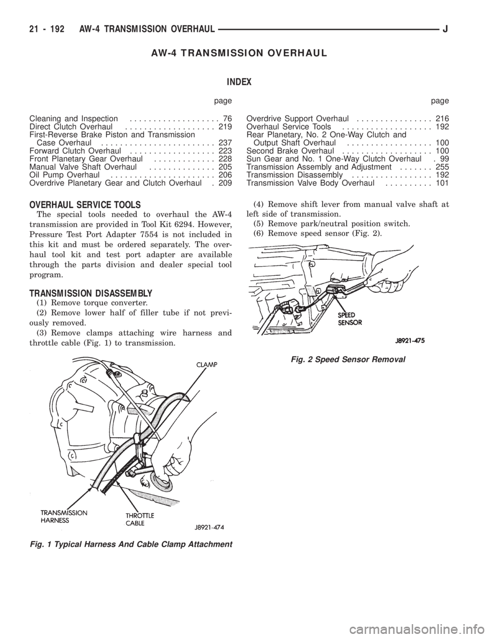
(3) Remove clamps attaching wire harness and
throttle cable (Fig. 1) to transmission.(4) Remove shift lever from manual valve shaft at
left side of transmission.
(5) Remove park/neutral position switch.
(6) Remove speed sensor (Fig. 2).
Fig. 1 Typical Harness And Cable Clamp Attachment
Fig. 2 Speed Sensor Removal
21 - 192 AW-4 TRANSMISSION OVERHAULJ
Page 1319 of 1784
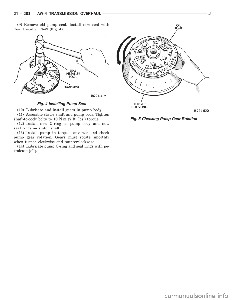
(9) Remove old pump seal. Install new seal with
Seal Installer 7549 (Fig. 4).
(10) Lubricate and install gears in pump body.
(11) Assemble stator shaft and pump body. Tighten
shaft-to-body bolts to 10 Nzm (7 ft. lbs.) torque.
(12) Install new O-ring on pump body and new
seal rings on stator shaft.
(13) Install pump in torque converter and check
pump gear rotation. Gears must rotate smoothly
when turned clockwise and counterclockwise.
(14) Lubricate pump O-ring and seal rings with pe-
troleum jelly.
Fig. 5 Checking Pump Gear Rotation
Fig. 4 Installing Pump Seal
21 - 208 AW-4 TRANSMISSION OVERHAULJ
Page 1321 of 1784
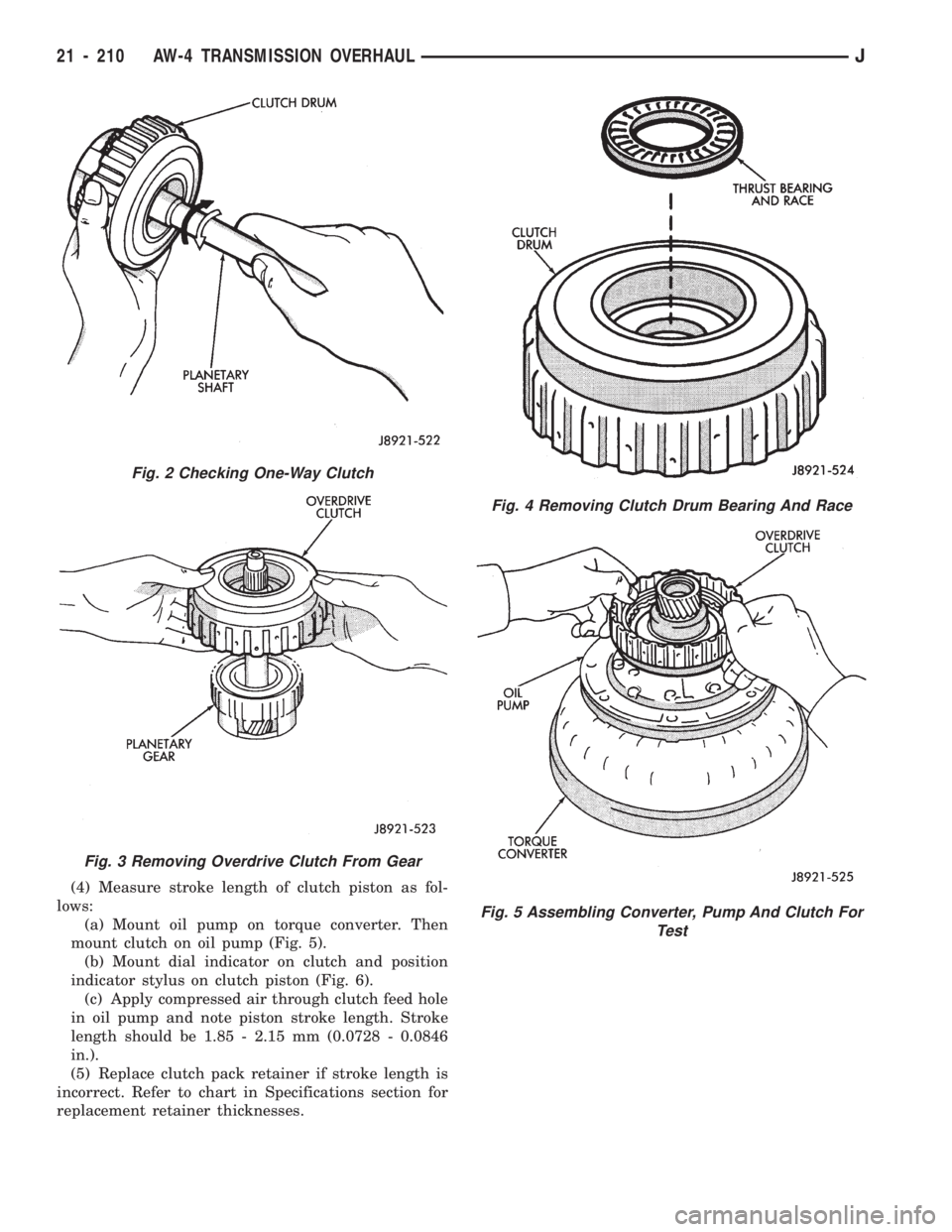
(4) Measure stroke length of clutch piston as fol-
lows:
(a) Mount oil pump on torque converter. Then
mount clutch on oil pump (Fig. 5).
(b) Mount dial indicator on clutch and position
indicator stylus on clutch piston (Fig. 6).
(c) Apply compressed air through clutch feed hole
in oil pump and note piston stroke length. Stroke
length should be 1.85 - 2.15 mm (0.0728 - 0.0846
in.).
(5) Replace clutch pack retainer if stroke length is
incorrect. Refer to chart in Specifications section for
replacement retainer thicknesses.
Fig. 2 Checking One-Way Clutch
Fig. 3 Removing Overdrive Clutch From Gear
Fig. 4 Removing Clutch Drum Bearing And Race
Fig. 5 Assembling Converter, Pump And Clutch For
Test
21 - 210 AW-4 TRANSMISSION OVERHAULJ