1994 JEEP CHEROKEE torque
[x] Cancel search: torquePage 1261 of 1784
GOVERNOR AND PARK GEAR INSTALLATION
(1) Lubricate governor components and park gear
seal rings with transmission fluid.
(2) Install governor filter in park gear and install
governor body on gear. Align governor body on gear
using marks made at disassembly.
(3) Install new seal rings on hub of park gear if
necessary. Be sure ring (or rings) with hooked ends
are properly connected.
(4) Install governor weight assembly in governor
body. Be sure governor weight snap rings are se-
curely seated.
(5) Align and install governor/park gear assembly
on output shaft as follows:
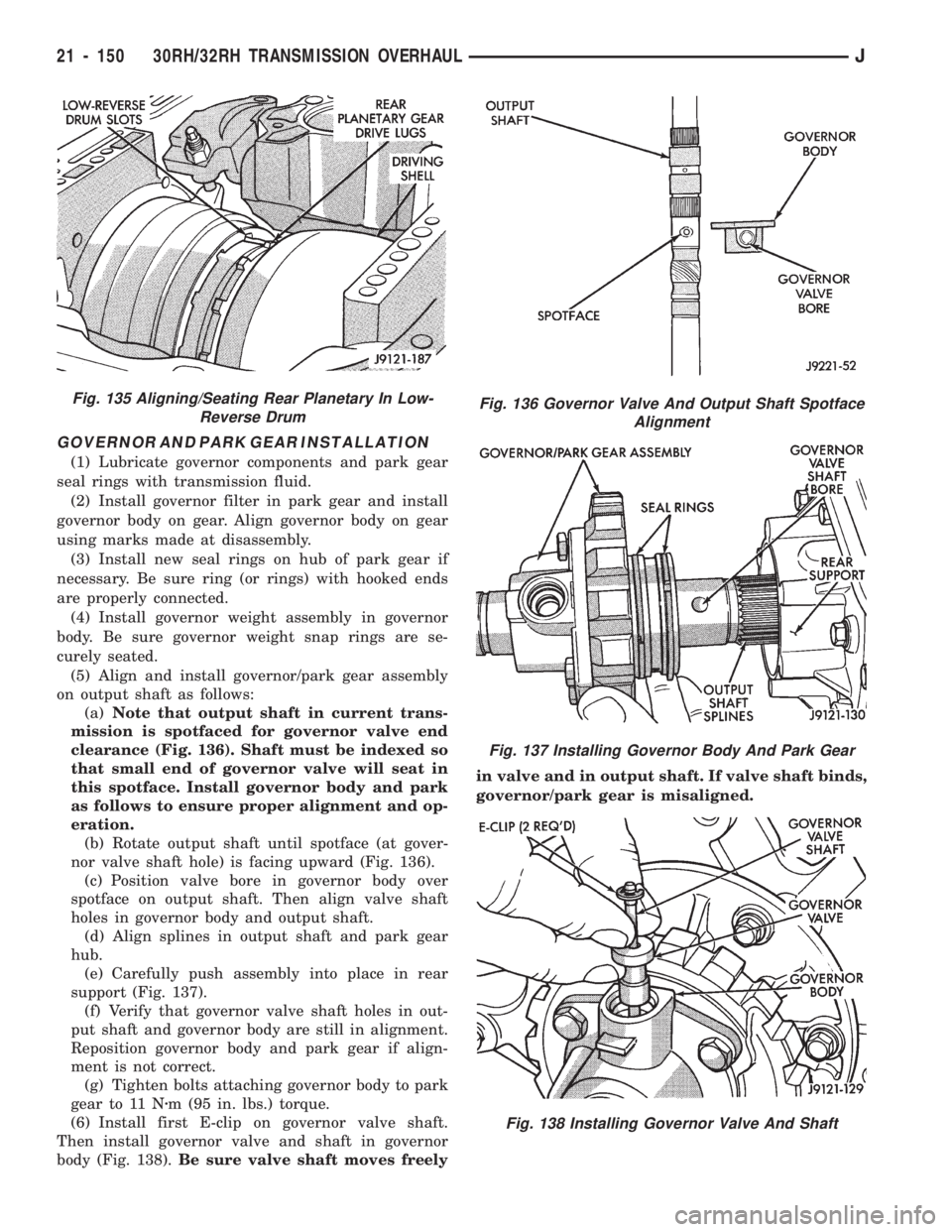
(a)Note that output shaft in current trans-
mission is spotfaced for governor valve end
clearance (Fig. 136). Shaft must be indexed so
that small end of governor valve will seat in
this spotface. Install governor body and park
as follows to ensure proper alignment and op-
eration.
(b) Rotate output shaft until spotface (at gover-
nor valve shaft hole) is facing upward (Fig. 136).
(c) Position valve bore in governor body over
spotface on output shaft. Then align valve shaft
holes in governor body and output shaft.
(d) Align splines in output shaft and park gear
hub.
(e) Carefully push assembly into place in rear
support (Fig. 137).
(f) Verify that governor valve shaft holes in out-
put shaft and governor body are still in alignment.
Reposition governor body and park gear if align-
ment is not correct.
(g) Tighten bolts attaching governor body to park
gear to 11 Nzm (95 in. lbs.) torque.
(6) Install first E-clip on governor valve shaft.
Then install governor valve and shaft in governor
body (Fig. 138).Be sure valve shaft moves freelyin valve and in output shaft. If valve shaft binds,
governor/park gear is misaligned.
Fig. 136 Governor Valve And Output Shaft Spotface
Alignment
Fig. 137 Installing Governor Body And Park Gear
Fig. 138 Installing Governor Valve And Shaft
Fig. 135 Aligning/Seating Rear Planetary In Low-
Reverse Drum
21 - 150 30RH/32RH TRANSMISSION OVERHAULJ
Page 1265 of 1784
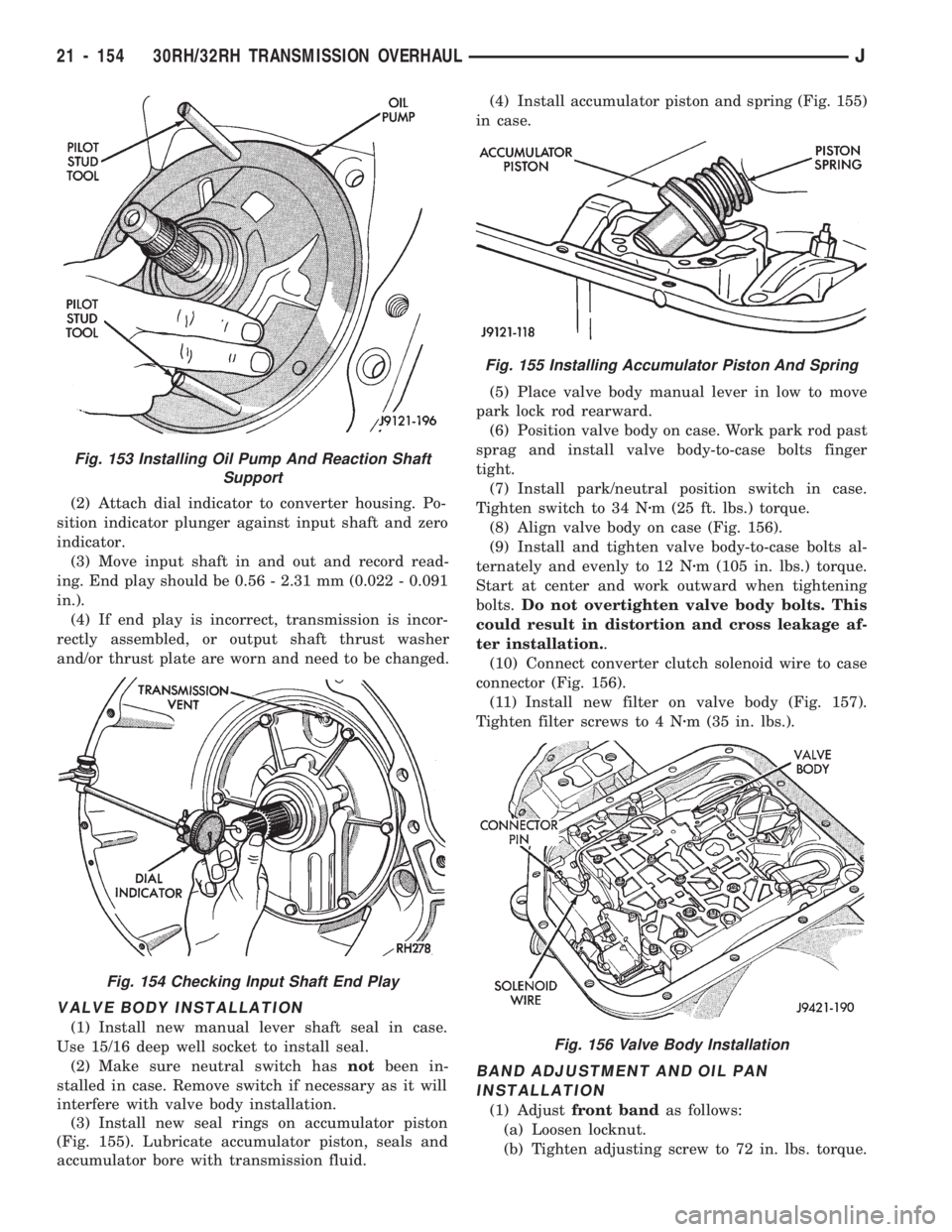
(2) Attach dial indicator to converter housing. Po-
sition indicator plunger against input shaft and zero
indicator.
(3) Move input shaft in and out and record read-
ing. End play should be 0.56 - 2.31 mm (0.022 - 0.091
in.).
(4) If end play is incorrect, transmission is incor-
rectly assembled, or output shaft thrust washer
and/or thrust plate are worn and need to be changed.
VALVE BODY INSTALLATION
(1) Install new manual lever shaft seal in case.
Use 15/16 deep well socket to install seal.
(2) Make sure neutral switch hasnotbeen in-
stalled in case. Remove switch if necessary as it will
interfere with valve body installation.
(3) Install new seal rings on accumulator piston
(Fig. 155). Lubricate accumulator piston, seals and
accumulator bore with transmission fluid.(4) Install accumulator piston and spring (Fig. 155)
in case.
(5) Place valve body manual lever in low to move
park lock rod rearward.
(6) Position valve body on case. Work park rod past
sprag and install valve body-to-case bolts finger
tight.
(7) Install park/neutral position switch in case.
Tighten switch to 34 Nzm (25 ft. lbs.) torque.
(8) Align valve body on case (Fig. 156).
(9) Install and tighten valve body-to-case bolts al-
ternately and evenly to 12 Nzm (105 in. lbs.) torque.
Start at center and work outward when tightening
bolts.Do not overtighten valve body bolts. This
could result in distortion and cross leakage af-
ter installation..
(10) Connect converter clutch solenoid wire to case
connector (Fig. 156).
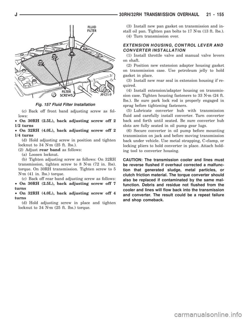
(11) Install new filter on valve body (Fig. 157).
Tighten filter screws to 4 Nzm (35 in. lbs.).
BAND ADJUSTMENT AND OIL PAN
INSTALLATION
(1) Adjustfront bandas follows:
(a) Loosen locknut.
(b) Tighten adjusting screw to 72 in. lbs. torque.
Fig. 153 Installing Oil Pump And Reaction Shaft
Support
Fig. 154 Checking Input Shaft End Play
Fig. 155 Installing Accumulator Piston And Spring
Fig. 156 Valve Body Installation
21 - 154 30RH/32RH TRANSMISSION OVERHAULJ
Page 1266 of 1784
(c) Back off front band adjusting screw as fol-
lows:
²On 30RH (2.5L), back adjusting screw off 2
1/2 turns
²On 32RH (4.0L), back adjusting screw off 2
1/4 turns
(d) Hold adjusting screw in position and tighten
locknut to 34 Nzm (25 ft. lbs.).
(2) Adjustrear bandas follows:
(a) Loosen locknut.
(b) Tighten adjusting screw as follows: On 32RH
transmission, tighten screw to 8 Nzm (72 in. lbs).
torque. On 30RH transmission. Tighten screw to 5
Nzm (41 in. lbs.) torque.
(c) Back off rear band adjusting screw as follows:
²On 30RH (2.5L), back adjusting screw off 7
turns
²On 32RH (4.0L), back adjusting screw off 4
turns
(d) Hold adjusting screw in place and tighten
locknut to 34 Nzm (25 ft. lbs.) torque.(3) Install new pan gasket on transmission and in-
stall oil pan. Tighten pan bolts to 17 Nzm (13 ft. lbs.).
(4) Turn transmission over.
EXTENSION HOUSING, CONTROL LEVER AND
CONVERTER INSTALLATION
(1) Install throttle valve and manual valve levers
on shaft.
(2) Position new extension adapter housing gasket
on transmission case. Use petroleum jelly to hold
gasket in place.
(3) Install new rear seal in extension housing if re-
quired.
(4) Install extension/adapter housing on transmis-
sion case. Tighten housing fasteners to 33 Nzm (24 ft.
lbs.). Be sure park lock rod is properly engaged in
sprag before tightening fasteners.
(5) Lubricate converter hub with transmission
fluid and carefully install converter. Turn converter
back and forth until seated. Be sure converter hub
slots are fully seated in oil pump gear lugs.
(6) Secure converter in oil pump before mounting
transmission on jack and before moving transmission
back under vehicle. Use metal strapping, C-clamp, or
locking pliers to hold converter in place. Attach hold-
ing tool to converter housing.
CAUTION: The transmission cooler and lines must
be reverse flushed if overhaul corrected a malfunc-
tion that generated sludge, metal particles, or
clutch friction material. The torque converter should
also be replaced if contaminated by the same mal-
function. Debris and residue not flushed from the
cooler and lines will flow back into the transmission
and converter. The result could be a repeat failure
and shop comeback.
Fig. 157 Fluid Filter Installation
J30RH/32RH TRANSMISSION OVERHAUL 21 - 155
Page 1267 of 1784
AW-4 AUTOMATIC TRANSMISSION
CONTENTS
page page
AW-4 IN-VEHICLE SERVICE............. 173
AW-4 TRANSMISSION DIAGNOSIS........ 167
AW-4 TRANSMISSION OVERHAUL........ 192
AW-4 TRANSMISSION REMOVAL AND
INSTALLATION....................... 189GENERAL INFORMATION................ 156
TRANSMISSION/TRANSFER CASE
SPECIFICATIONS..................... 320
GENERAL INFORMATION
INDEX
page page
Components and Operation................ 157
Description............................ 156
FirstÐThirdÐReverse Gear Components...... 159
Fourth Gear Overdrive Components......... 158
Geartrain Operation and Application Charts.... 159Hydraulic System........................ 160
Torque Converter........................ 158
Transmission Identification................. 157
Transmission Ranges and Shift Lever Positions . 157
DESCRIPTION
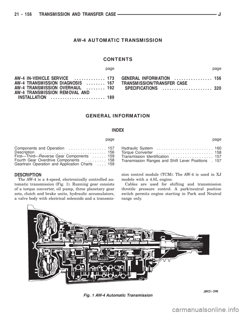
The AW-4 is a 4-speed, electronically controlled au-
tomatic transmission (Fig. 1). Running gear consists
of a torque converter, oil pump, three planetary gear
sets, clutch and brake units, hydraulic accumulators,
a valve body with electrical solenoids and a transmis-sion control module (TCM). The AW-4 is used in XJ
models with a 4.0L engine.
Cables are used for shifting and transmission
throttle pressure control. A park/neutral position
switch permits engine starting in Park and Neutral
range only.
Fig. 1 AW-4 Automatic Transmission
21 - 156 TRANSMISSION AND TRANSFER CASEJ
Page 1269 of 1784
net complete one revolution. Sensor signals are sent
to the transmission control module.
The park/neutral position switch is mounted on the
valve body manual shaft. The switch signals shift
linkage and manual valve position to the transmis-
sion control module through an interconnecting har-
ness. The switch prevents engine starting in all gears
other than Park or Neutral.
The brake switch is in circuit with the torque con-
verter clutch solenoid. The switch disengages the
converter clutch whenever the brakes are applied.
The switch is mounted on the brake pedal bracket
and signals the transmission control module when
the pedal is pressed or released.
TORQUE CONVERTER
A four element torque converter is used for all ap-
plications. The converter consists of the front cover
and pump, stator, turbine, and an electronic modu-
lated converter clutch mechanism.
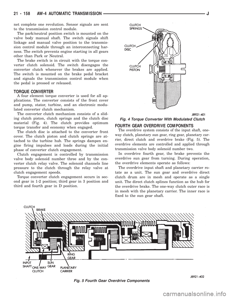
The converter clutch mechanism consists of a slid-
ing clutch piston, clutch springs and the clutch disc
material (Fig. 4). The clutch provides optimum
torque transfer and economy when engaged.
The clutch disc is attached to the converter front
cover. The clutch piston and clutch springs are at-
tached to the turbine hub. The springs dampen en-
gine firing impulses and loads during the initial
phase of converter clutch engagement.
Clutch engagement is controlled by transmission
valve body solenoid number three and by the con-
verter clutch relay valve. The solenoid channels line
pressure to the clutch through the relay valve at
clutch engagement speeds.
Torque converter clutch engagement occurs in sec-
ond gear in 1-2 position; third gear in 3 position and
third and fourth gear in D position.
FOURTH GEAR OVERDRIVE COMPONENTS
The overdrive system consists of the input shaft, one-
way clutch, planetary sun gear, ring gear, planetary car-
rier, direct clutch and overdrive brake (Fig. 5). The
overdrive elements are controlled and applied through
transmission valve body solenoid number two.
In overdrive fourth gear, the brake prevents the
overdrive sun gear from turning. During operation,
the overdrive elements operate as follows:
The overdrive input shaft and planetary carrier ro-
tate as a unit. The sun gear and overdrive direct
clutch drum are in mesh and operate as a single
unit. The direct clutch splines function as the hub for
the overdrive brake. The one-way clutch outer race is
in mesh with the planetary carrier. The inner race is
fixed to the sun gear shaft.
Fig. 5 Fourth Gear Overdrive Components
Fig. 4 Torque Converter With Modulated Clutch
21 - 158 AW-4 AUTOMATIC TRANSMISSIONJ
Page 1271 of 1784
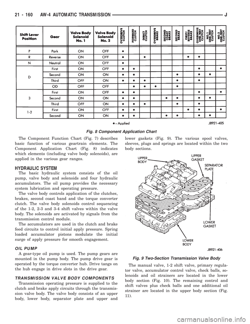
The Component Function Chart (Fig. 7) describes
basic function of various geartrain elements. The
Component Application Chart (Fig. 8) indicates
which elements (including valve body solenoids), are
applied in the various gear ranges.
HYDRAULIC SYSTEM
The basic hydraulic system consists of the oil
pump, valve body and solenoids and four hydraulic
accumulators. The oil pump provides the necessary
system lubrication and operating pressure.
The valve body controls application of the clutches,
brakes, second coast band and the torque converter
clutch. The valve body solenoids control sequencing
of the 1-2, 2-3 and 3-4 shift valves within the valve
body. The solenoids are activated by signals from the
transmission control module.
The accumulators are used in the clutch and brake
feed circuits to control initial apply pressure. Spring
loaded accumulator pistons modulate the initial
surge of apply pressure for smooth engagement.
OIL PUMP
A gear-type oil pump is used. The pump gears are
mounted in the pump body. The pump drive gear is
operated by the torque converter hub. Drive tangs on
the hub engage in drive slots in the drive gear.
TRANSMISSION VALVE BODY COMPONENTS
Transmission operating pressure is supplied to the
clutch and brake apply circuits through the transmis-
sion valve body. The valve body consists of an upper
body, lower body, separator plate and upper andlower gaskets (Fig. 9). The various spool valves,
sleeves, plugs and springs are located within the two
body sections.
The manual valve, 1-2 shift valve, primary regula-
tor valve, accumulator control valve, check balls, so-
lenoids and oil strainers are located in the lower
body section (Fig. 10). The remaining control and
shift valves plus check balls and one additional oil
strainer are located in the upper body section (Fig.
11).
Fig. 8 Component Application Chart
Fig. 9 Two-Section Transmission Valve Body
21 - 160 AW-4 AUTOMATIC TRANSMISSIONJ
Page 1277 of 1784
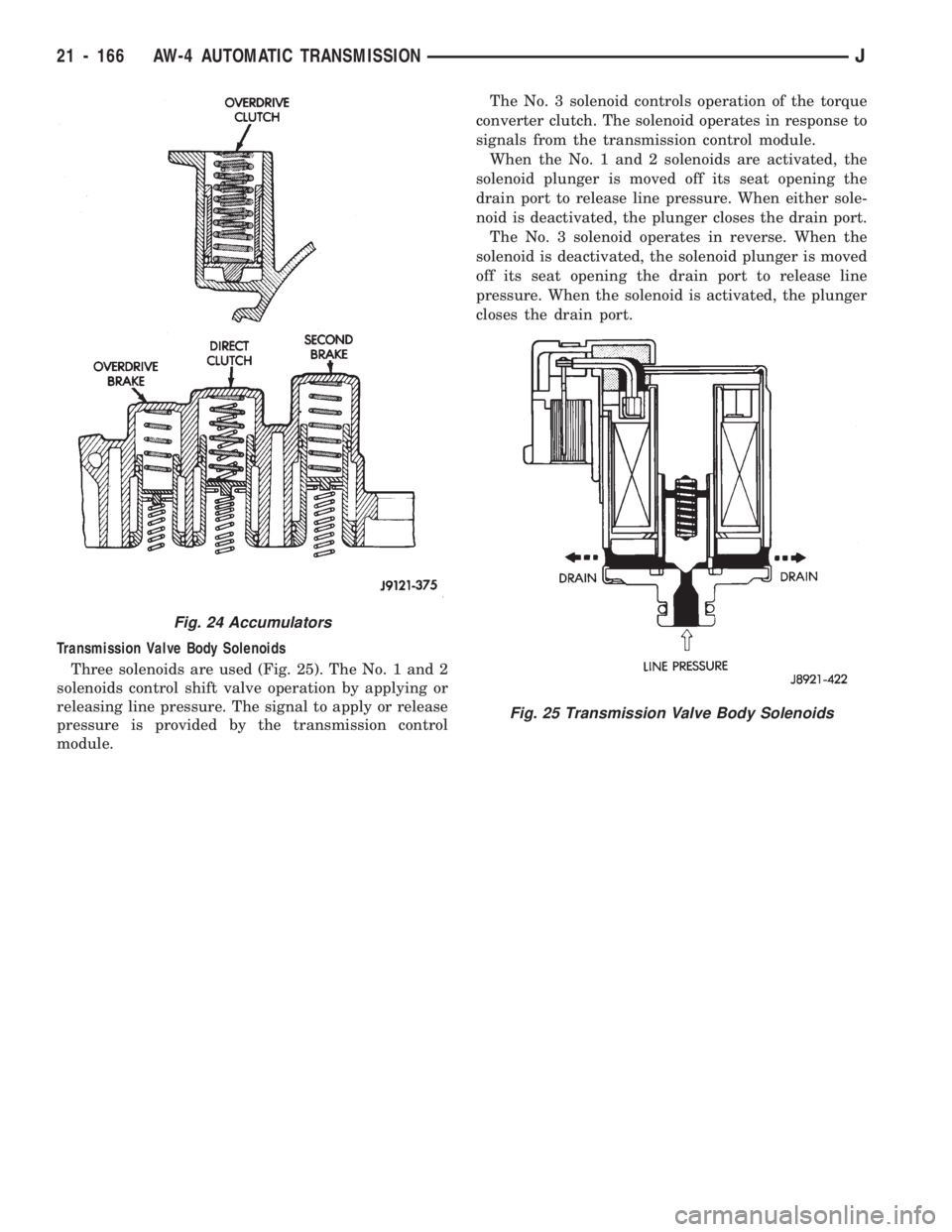
Transmission Valve Body Solenoids
Three solenoids are used (Fig. 25). The No. 1 and 2
solenoids control shift valve operation by applying or
releasing line pressure. The signal to apply or release
pressure is provided by the transmission control
module.The No. 3 solenoid controls operation of the torque
converter clutch. The solenoid operates in response to
signals from the transmission control module.
When the No. 1 and 2 solenoids are activated, the
solenoid plunger is moved off its seat opening the
drain port to release line pressure. When either sole-
noid is deactivated, the plunger closes the drain port.
The No. 3 solenoid operates in reverse. When the
solenoid is deactivated, the solenoid plunger is moved
off its seat opening the drain port to release line
pressure. When the solenoid is activated, the plunger
closes the drain port.
Fig. 24 Accumulators
Fig. 25 Transmission Valve Body Solenoids
21 - 166 AW-4 AUTOMATIC TRANSMISSIONJ
Page 1278 of 1784
AW-4 TRANSMISSION DIAGNOSIS
INDEX
page page
General Diagnosis Information.............. 167
Hydraulic Pressure Test................... 168
Manual Shifting Test..................... 168Preliminary Inspection and Adjustment........ 167
Time Lag Test .......................... 169
Torque Converter Stall Test................ 169
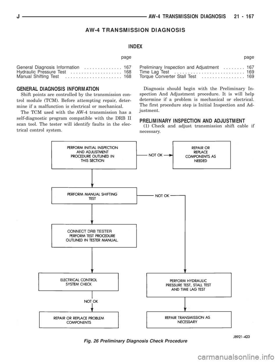
GENERAL DIAGNOSIS INFORMATION
Shift points are controlled by the transmission con-
trol module (TCM). Before attempting repair, deter-
mine if a malfunction is electrical or mechanical.
The TCM used with the AW-4 transmission has a
self-diagnostic program compatible with the DRB II
scan tool. The tester will identify faults in the elec-
trical control system.Diagnosis should begin with the Preliminary In-
spection And Adjustment procedure. It is will help
determine if a problem is mechanical or electrical.
The first procedure step is Initial Inspection and Ad-
justment.
PRELIMINARY INSPECTION AND ADJUSTMENT
(1) Check and adjust transmission shift cable if
necessary.
Fig. 26 Preliminary Diagnosis Check Procedure
JAW-4 TRANSMISSION DIAGNOSIS 21 - 167