Page 1139 of 1784
(20) Install new shift rail C-rings (Fig. 90).
(21) Apply sealer to threads of lock ball plugs.
(22) Install lock balls and springs in intermediate
plate.Short spring goes in top hole of interme-
diate plate.
(23) Install lock ball and spring plugs (Fig. 91).
Tighten plugs to 19 Nzm (14 ft. lbs.) torque.ASSEMBLING GEARTRAIN AND
TRANSMISSION CASE
(1) Remove intermediate plate from vise.
(2) Install new gaskets on intermediate plate.
(3) Install transmission case on intermediate plate
(Fig. 92).
(4) Install new front bearing snap ring (Fig. 93).
Fig. 92 Installing Transmission Case
Fig. 93 Installing Front Bearing Snap Ring
Fig. 90 Installing Shift Rail C-Rings
Fig. 91 Installing Lock Ball Plugs
21 - 28 AX 4/5 MANUAL TRANSMISSIONJ
Page 1140 of 1784
(5) Install new gasket on front bearing retainer
and install retainer on case (Fig. 94).
(6) Install adapter or extension housing on inter-
mediate plate (Fig. 95). Tighten housing bolts to 37
Nzm (27 ft. lbs.) torque.
(7) Install shift arm (Fig. 95).(8) Install shift arm lock plate with pliers (Fig. 96).
Then install and tighten lock plate set bolt to 38 Nzm
(28 ft. lbs.) torque.
(9) Install and tighten shaft plug to 18 Nzm (13 ft.
lbs.) torque (Fig. 97).
Fig. 94 Installing Front Bearing Retainer
Fig. 95 Installing Adapter Housing And Shift Arm
Fig. 96 Shift Arm Lock Plate Installation
Fig. 97 Shaft Plug Installation
JAX 4/5 MANUAL TRANSMISSION 21 - 29
Page 1141 of 1784
(10) Install lock ball and spring in housing. Then
apply sealer to ball plug and install plug (Fig. 98).
Tighten plug to 19 Nzm (14 ft. lbs.) torque.
(11) Install reverse pins in housing (Fig. 99).
Tighten pins to 27 Nzm (20 ft. lbs.) torque.(12) Install shift tower and new gasket on housing
(Fig. 100). Tighten tower bolts to 18 Nzm (13 ft. lbs.)
torque.
(13) Install backup lamp switch (Fig. 100). Tighten
switch to 37 Nzm (27 ft. lbs.) torque.
(14) On 2-wheel drive models, install new seal in
extension housing (Fig. 101).
Fig. 98 Installing Ball Plug
Fig. 99 Install Reverse Pins
Fig. 100 Installing Shift Tower And Backup Lamp
Switch
Fig. 101 Extension Housing Seal InstallationÐ2WD
Models
21 - 30 AX 4/5 MANUAL TRANSMISSIONJ
Page 1146 of 1784

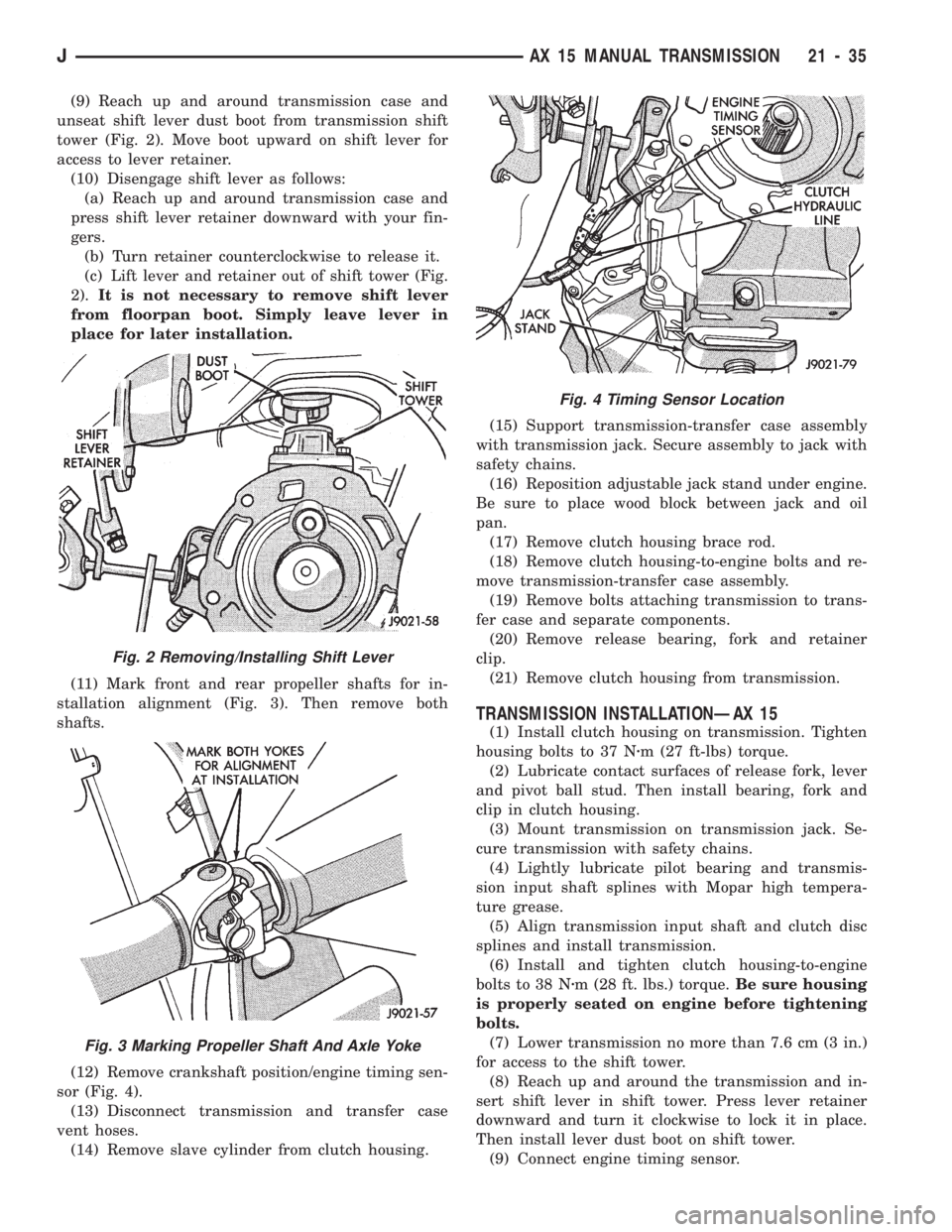
(9) Reach up and around transmission case and
unseat shift lever dust boot from transmission shift
tower (Fig. 2). Move boot upward on shift lever for
access to lever retainer.
(10) Disengage shift lever as follows:
(a) Reach up and around transmission case and
press shift lever retainer downward with your fin-
gers.
(b) Turn retainer counterclockwise to release it.
(c) Lift lever and retainer out of shift tower (Fig.
2).It is not necessary to remove shift lever
from floorpan boot. Simply leave lever in
place for later installation.
(11) Mark front and rear propeller shafts for in-
stallation alignment (Fig. 3). Then remove both
shafts.
(12) Remove crankshaft position/engine timing sen-
sor (Fig. 4).
(13) Disconnect transmission and transfer case
vent hoses.
(14) Remove slave cylinder from clutch housing.(15) Support transmission-transfer case assembly
with transmission jack. Secure assembly to jack with
safety chains.
(16) Reposition adjustable jack stand under engine.
Be sure to place wood block between jack and oil
pan.
(17) Remove clutch housing brace rod.
(18) Remove clutch housing-to-engine bolts and re-
move transmission-transfer case assembly.
(19) Remove bolts attaching transmission to trans-
fer case and separate components.
(20) Remove release bearing, fork and retainer
clip.
(21) Remove clutch housing from transmission.
TRANSMISSION INSTALLATIONÐAX 15
(1) Install clutch housing on transmission. Tighten
housing bolts to 37 Nzm (27 ft-lbs) torque.
(2) Lubricate contact surfaces of release fork, lever
and pivot ball stud. Then install bearing, fork and
clip in clutch housing.
(3) Mount transmission on transmission jack. Se-
cure transmission with safety chains.
(4) Lightly lubricate pilot bearing and transmis-
sion input shaft splines with Mopar high tempera-
ture grease.
(5) Align transmission input shaft and clutch disc
splines and install transmission.
(6) Install and tighten clutch housing-to-engine
bolts to 38 Nzm (28 ft. lbs.) torque.Be sure housing
is properly seated on engine before tightening
bolts.
(7) Lower transmission no more than 7.6 cm (3 in.)
for access to the shift tower.
(8) Reach up and around the transmission and in-
sert shift lever in shift tower. Press lever retainer
downward and turn it clockwise to lock it in place.
Then install lever dust boot on shift tower.
(9) Connect engine timing sensor.
Fig. 2 Removing/Installing Shift Lever
Fig. 3 Marking Propeller Shaft And Axle Yoke
Fig. 4 Timing Sensor Location
JAX 15 MANUAL TRANSMISSION 21 - 35
Page 1147 of 1784

(10) Remove jack from under transmission and
mount transfer case on jack.
(11) Align transfer case and transmission shafts
and install transfer case. Tighten transfer case-to-
transmission nuts/bolts to 35 Nzm (26 ft. lbs.) torque.
(12) Move jack stand from under engine and repo-
sition it under transmission. Then remove transmis-
sion jack.
(13) Connect transfer case vacuum hoses and link-
age. Check and adjust linkage if necessary.
(14) Connect transmission and transfer case vent
hoses and backup light switch wires.
(15) Install clutch sleeve cylinder.
(16) Connect vehicle speed sensor and wires.
(17) On XJ, install rear crossmember and attach
cushion and bracket. Tighten crossmember-to-frame
bolts to 41 Nzm (30 ft. lbs.) torque. Tighten transmis-
sion-to-rear cushion and bracket bolts/nuts to 45 Nzm
(33 ft. lbs.) torque.
(18) On YJ, install rear cushion and bracket and
skid plate. Tighten attaching bolts/nuts to indicated
torque (Fig. 1).
(19) Align and install front/rear propeller shafts.
Tighten shaft U-joint clamp bolts to 19 Nzm (170 in.
lbs.) torque.
(20) On XJ, install skid plate if removed. Tighten
bolts to 42 Nzm (31 ft. lbs.) torque. Tighten stud nuts
to 17 Nzm (150 in. lbs.) torque.
(21) Top off transmission and transfer lubricant
levels.
(22) Remove supports and lower vehicle.
TRANSMISSION DISASSEMBLY AND OVERHAUL
ADAPTER/EXTENSION HOUSING REMOVAL
(1) Remove release bearing, fork, retainer clip and
clutch housing from transmission. Also remove shift
lever if not previously removed.
(2) On 2-wheel drive models, remove extension
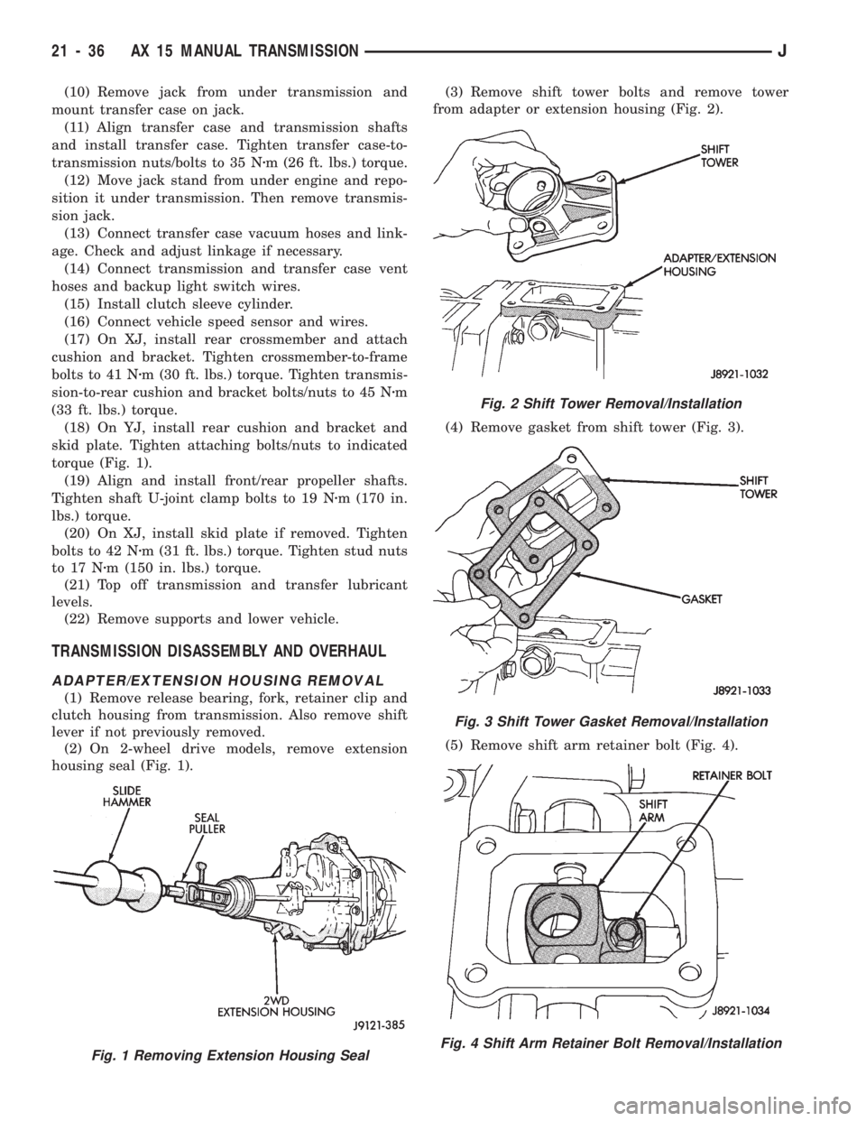
housing seal (Fig. 1).(3) Remove shift tower bolts and remove tower
from adapter or extension housing (Fig. 2).
(4) Remove gasket from shift tower (Fig. 3).
(5) Remove shift arm retainer bolt (Fig. 4).
Fig. 1 Removing Extension Housing Seal
Fig. 2 Shift Tower Removal/Installation
Fig. 3 Shift Tower Gasket Removal/Installation
Fig. 4 Shift Arm Retainer Bolt Removal/Installation
21 - 36 AX 15 MANUAL TRANSMISSIONJ
Page 1169 of 1784
(8) Install 1-2 shift rail in intermediate plate and
1-2 fork (Fig. 92).
(9) Coat 3-4 shift rail interlock plug with petro-
leum jelly and install plug in intermediate plate (Fig.
93).
(10) Install 3-4 shift rail in intermediate plate and
in both shift forks (Fig. 94).
(11) Verify that none of interlock balls, plugs, or
pins were displaced during shift rail installation.
(12) Install and tighten shift fork setscrews to 20
Nzm (14 ft. lbs.) torque (Fig. 95).
(13) Install 1-2 and 3-4 shift rail C-rings (Fig. 96).
(14) Insert fifth gear shift rail through reverse
shift fork.Then slide rail into intermediate plate
just far enough to secure interlock ball. Do not
fully install shift rail at this time.
Fig. 94 Installing 3-4 Shift Rail
Fig. 95 Installing Shift Fork Set Screws
Fig. 96 Installing Shift Rail C-Rings
Fig. 92 Installing 1-2 Shift Rail
Fig. 93 Installing 3-4 Shift Rail Interlock Plug
21 - 58 AX 15 MANUAL TRANSMISSIONJ
Page 1171 of 1784

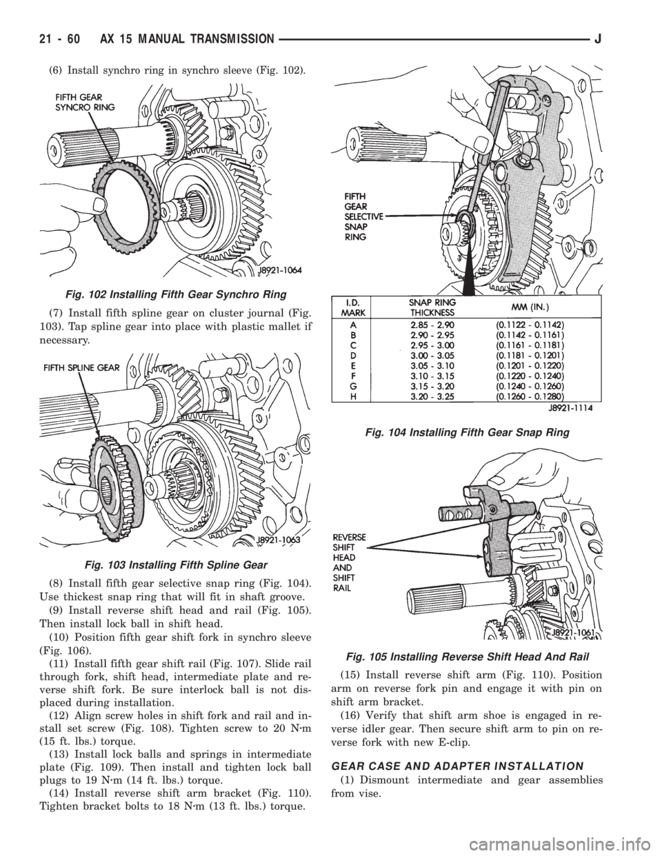
(6) Install synchro ring in synchro sleeve (Fig. 102).
(7) Install fifth spline gear on cluster journal (Fig.
103). Tap spline gear into place with plastic mallet if
necessary.
(8) Install fifth gear selective snap ring (Fig. 104).
Use thickest snap ring that will fit in shaft groove.
(9) Install reverse shift head and rail (Fig. 105).
Then install lock ball in shift head.
(10) Position fifth gear shift fork in synchro sleeve
(Fig. 106).
(11) Install fifth gear shift rail (Fig. 107). Slide rail
through fork, shift head, intermediate plate and re-
verse shift fork. Be sure interlock ball is not dis-
placed during installation.
(12) Align screw holes in shift fork and rail and in-
stall set screw (Fig. 108). Tighten screw to 20 Nzm
(15 ft. lbs.) torque.
(13) Install lock balls and springs in intermediate
plate (Fig. 109). Then install and tighten lock ball
plugs to 19 Nzm (14 ft. lbs.) torque.
(14) Install reverse shift arm bracket (Fig. 110).
Tighten bracket bolts to 18 Nzm (13 ft. lbs.) torque.(15) Install reverse shift arm (Fig. 110). Position
arm on reverse fork pin and engage it with pin on
shift arm bracket.
(16) Verify that shift arm shoe is engaged in re-
verse idler gear. Then secure shift arm to pin on re-
verse fork with new E-clip.
GEAR CASE AND ADAPTER INSTALLATION
(1) Dismount intermediate and gear assemblies
from vise.
Fig. 104 Installing Fifth Gear Snap Ring
Fig. 105 Installing Reverse Shift Head And Rail
Fig. 102 Installing Fifth Gear Synchro Ring
Fig. 103 Installing Fifth Spline Gear
21 - 60 AX 15 MANUAL TRANSMISSIONJ
Page 1173 of 1784

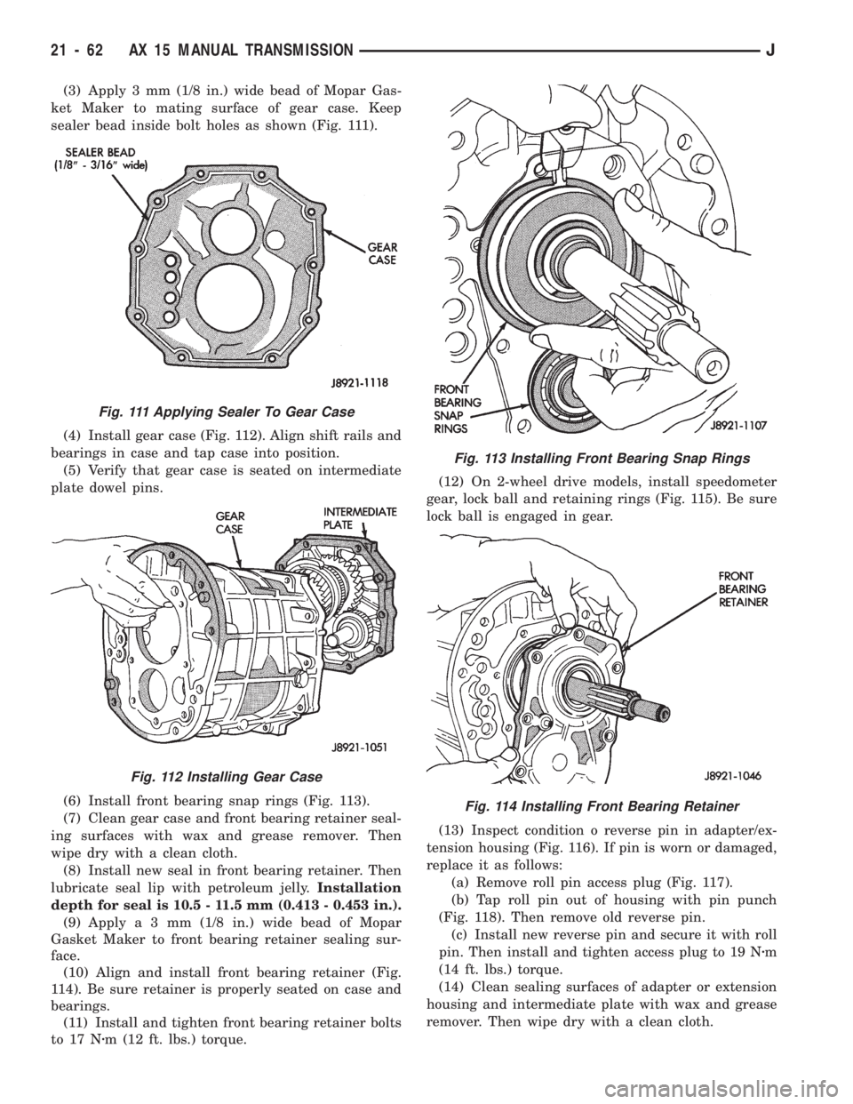
(3) Apply 3 mm (1/8 in.) wide bead of Mopar Gas-
ket Maker to mating surface of gear case. Keep
sealer bead inside bolt holes as shown (Fig. 111).
(4) Install gear case (Fig. 112). Align shift rails and
bearings in case and tap case into position.
(5) Verify that gear case is seated on intermediate
plate dowel pins.
(6) Install front bearing snap rings (Fig. 113).
(7) Clean gear case and front bearing retainer seal-
ing surfaces with wax and grease remover. Then
wipe dry with a clean cloth.
(8) Install new seal in front bearing retainer. Then
lubricate seal lip with petroleum jelly.Installation
depth for seal is 10.5 - 11.5 mm (0.413 - 0.453 in.).
(9) Applya3mm(1/8 in.) wide bead of Mopar
Gasket Maker to front bearing retainer sealing sur-
face.
(10) Align and install front bearing retainer (Fig.
114). Be sure retainer is properly seated on case and
bearings.
(11) Install and tighten front bearing retainer bolts
to 17 Nzm (12 ft. lbs.) torque.(12) On 2-wheel drive models, install speedometer
gear, lock ball and retaining rings (Fig. 115). Be sure
lock ball is engaged in gear.
(13) Inspect condition o reverse pin in adapter/ex-
tension housing (Fig. 116). If pin is worn or damaged,
replace it as follows:
(a) Remove roll pin access plug (Fig. 117).
(b) Tap roll pin out of housing with pin punch
(Fig. 118). Then remove old reverse pin.
(c) Install new reverse pin and secure it with roll
pin. Then install and tighten access plug to 19 Nzm
(14 ft. lbs.) torque.
(14) Clean sealing surfaces of adapter or extension
housing and intermediate plate with wax and grease
remover. Then wipe dry with a clean cloth.
Fig. 111 Applying Sealer To Gear Case
Fig. 112 Installing Gear Case
Fig. 113 Installing Front Bearing Snap Rings
Fig. 114 Installing Front Bearing Retainer
21 - 62 AX 15 MANUAL TRANSMISSIONJ