Page 1472 of 1784
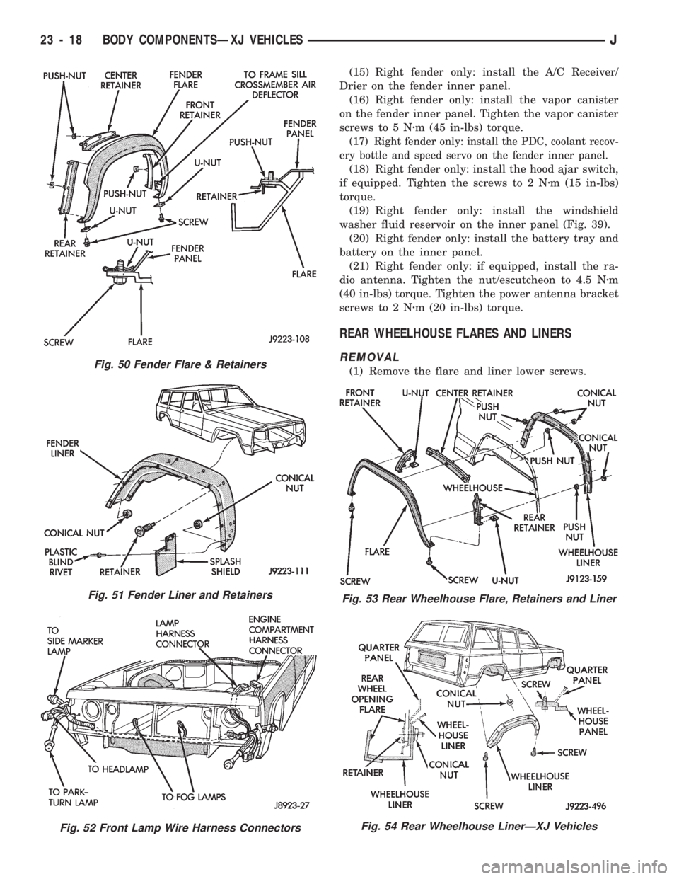
²install the nuts to attach the fender liner to the
fender and flare retainers (Fig. 48);
²install the retainers to attach the fender liner to
the fender inner panel;
²install the rivets to attach the flare to the air de-
flector (Figs. 48 and 50); and
²install the screws to attach the flare to the fender.
Tighten the screws to 1 Nzm (13 in-lbs) torque.
(8) Connect the front lamp wire harness connectors
to the engine wire harness connectors (Fig. 52).(9) Install the front lamps.
(10) Install the front bumper.
(11) Install the wheel, remove the support and
lower the vehicle.
(12) Right fender only: install the hood support rod
on the fender inner panel.
(13) Install the hood bumper on the fender inner
panel.
(14) Right fender only: install the Daytime Run-
ning Light (DRL) module on fender inner panel.
Fig. 48 Fender Flare & Liner Removal/Installation
Fig. 49 Fender Removal/Installation
JBODY COMPONENTSÐXJ VEHICLES 23 - 17
Page 1473 of 1784
(15) Right fender only: install the A/C Receiver/
Drier on the fender inner panel.
(16) Right fender only: install the vapor canister
on the fender inner panel. Tighten the vapor canister
screws to 5 Nzm (45 in-lbs) torque.
(17) Right fender only: install the PDC, coolant recov-
ery bottle and speed servo on the fender inner panel.
(18) Right fender only: install the hood ajar switch,
if equipped. Tighten the screws to 2 Nzm (15 in-lbs)
torque.
(19) Right fender only: install the windshield
washer fluid reservoir on the inner panel (Fig. 39).
(20) Right fender only: install the battery tray and
battery on the inner panel.
(21) Right fender only: if equipped, install the ra-
dio antenna. Tighten the nut/escutcheon to 4.5 Nzm
(40 in-lbs) torque. Tighten the power antenna bracket
screws to 2 Nzm (20 in-lbs) torque.
REAR WHEELHOUSE FLARES AND LINERS
REMOVAL
(1) Remove the flare and liner lower screws.Fig. 50 Fender Flare & Retainers
Fig. 51 Fender Liner and Retainers
Fig. 52 Front Lamp Wire Harness Connectors
Fig. 53 Rear Wheelhouse Flare, Retainers and Liner
Fig. 54 Rear Wheelhouse LinerÐXJ Vehicles
23 - 18 BODY COMPONENTSÐXJ VEHICLESJ
Page 1474 of 1784
(2) Remove the nuts that attach the liner to the
wheelhouse.
(3) Remove the liner from the wheelhouse.
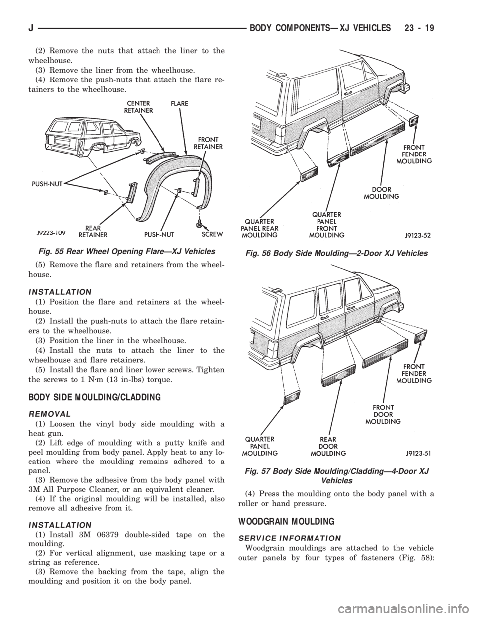
(4) Remove the push-nuts that attach the flare re-
tainers to the wheelhouse.
(5) Remove the flare and retainers from the wheel-
house.
INSTALLATION
(1) Position the flare and retainers at the wheel-
house.
(2) Install the push-nuts to attach the flare retain-
ers to the wheelhouse.
(3) Position the liner in the wheelhouse.
(4) Install the nuts to attach the liner to the
wheelhouse and flare retainers.
(5) Install the flare and liner lower screws. Tighten
the screws to 1 Nzm (13 in-lbs) torque.
BODY SIDE MOULDING/CLADDING
REMOVAL
(1) Loosen the vinyl body side moulding with a
heat gun.
(2) Lift edge of moulding with a putty knife and
peel moulding from body panel. Apply heat to any lo-
cation where the moulding remains adhered to a
panel.
(3) Remove the adhesive from the body panel with
3M All Purpose Cleaner, or an equivalent cleaner.
(4) If the original moulding will be installed, also
remove all adhesive from it.
INSTALLATION
(1) Install 3M 06379 double-sided tape on the
moulding.
(2) For vertical alignment, use masking tape or a
string as reference.
(3) Remove the backing from the tape, align the
moulding and position it on the body panel.(4) Press the moulding onto the body panel with a
roller or hand pressure.
WOODGRAIN MOULDING
SERVICE INFORMATION
Woodgrain mouldings are attached to the vehicle
outer panels by four types of fasteners (Fig. 58):
Fig. 56 Body Side MouldingÐ2-Door XJ Vehicles
Fig. 57 Body Side Moulding/CladdingÐ4-Door XJ
Vehicles
Fig. 55 Rear Wheel Opening FlareÐXJ Vehicles
JBODY COMPONENTSÐXJ VEHICLES 23 - 19
Page 1475 of 1784
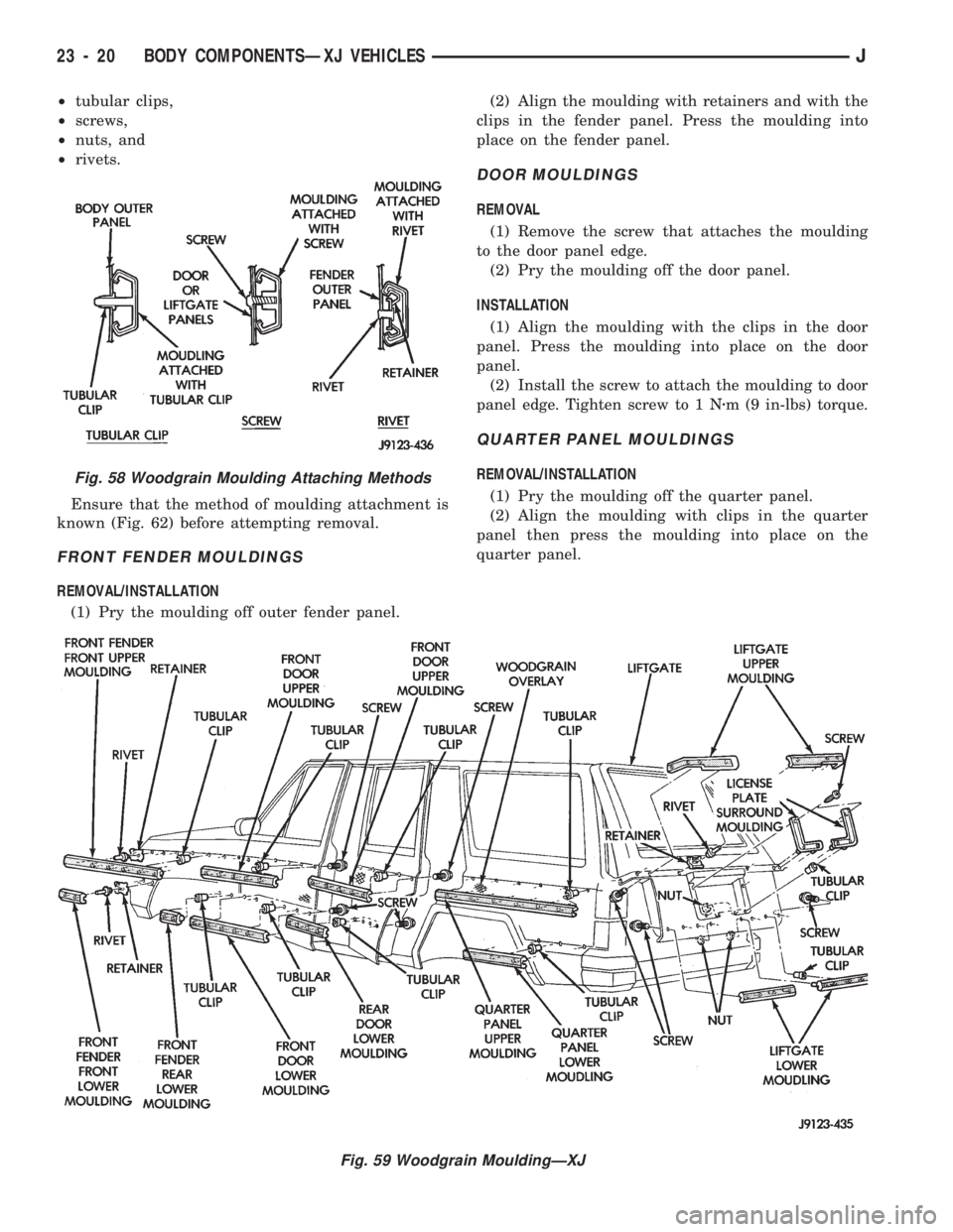
²tubular clips,
²screws,
²nuts, and
²rivets.
Ensure that the method of moulding attachment is
known (Fig. 62) before attempting removal.
FRONT FENDER MOULDINGS
REMOVAL/INSTALLATION
(1) Pry the moulding off outer fender panel.(2) Align the moulding with retainers and with the
clips in the fender panel. Press the moulding into
place on the fender panel.
DOOR MOULDINGS
REMOVAL
(1) Remove the screw that attaches the moulding
to the door panel edge.
(2) Pry the moulding off the door panel.
INSTALLATION
(1) Align the moulding with the clips in the door
panel. Press the moulding into place on the door
panel.
(2) Install the screw to attach the moulding to door
panel edge. Tighten screw to 1 Nzm (9 in-lbs) torque.
QUARTER PANEL MOULDINGS
REMOVAL/INSTALLATION
(1) Pry the moulding off the quarter panel.
(2) Align the moulding with clips in the quarter
panel then press the moulding into place on the
quarter panel.
Fig. 59 Woodgrain MouldingÐXJ
Fig. 58 Woodgrain Moulding Attaching Methods
23 - 20 BODY COMPONENTSÐXJ VEHICLESJ
Page 1476 of 1784
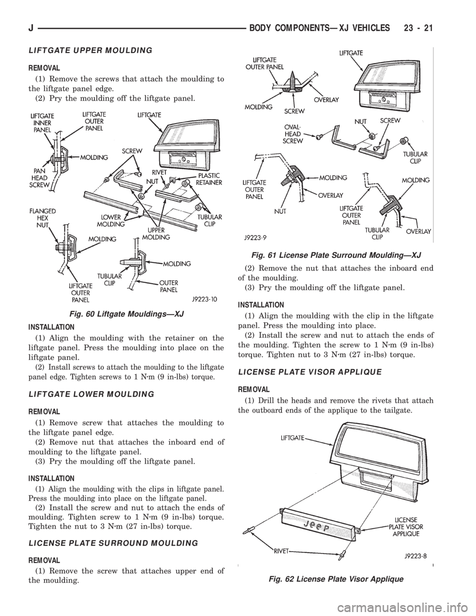
LIFTGATE UPPER MOULDING
REMOVAL
(1) Remove the screws that attach the moulding to
the liftgate panel edge.
(2) Pry the moulding off the liftgate panel.
INSTALLATION
(1) Align the moulding with the retainer on the
liftgate panel. Press the moulding into place on the
liftgate panel.
(2) Install screws to attach the moulding to the liftgate
panel edge. Tighten screws to 1 Nzm (9 in-lbs) torque.
LIFTGATE LOWER MOULDING
REMOVAL
(1) Remove screw that attaches the moulding to
the liftgate panel edge.
(2) Remove nut that attaches the inboard end of
moulding to the liftgate panel.
(3) Pry the moulding off the liftgate panel.
INSTALLATION
(1) Align the moulding with the clips in liftgate panel.
Press the moulding into place on the liftgate panel.
(2) Install the screw and nut to attach the ends of
moulding. Tighten screw to 1 Nzm (9 in-lbs) torque.
Tighten the nut to 3 Nzm (27 in-lbs) torque.
LICENSE PLATE SURROUND MOULDING
REMOVAL
(1) Remove the screw that attaches upper end of
the moulding.(2) Remove the nut that attaches the inboard end
of the moulding.
(3) Pry the moulding off the liftgate panel.
INSTALLATION
(1) Align the moulding with the clip in the liftgate
panel. Press the moulding into place.
(2) Install the screw and nut to attach the ends of
the moulding. Tighten the screw to 1 Nzm (9 in-lbs)
torque. Tighten nut to 3 Nzm (27 in-lbs) torque.
LICENSE PLATE VISOR APPLIQUE
REMOVAL
(1) Drill the heads and remove the rivets that attach
the outboard ends of the applique to the tailgate.
Fig. 61 License Plate Surround MouldingÐXJ
Fig. 62 License Plate Visor Applique
Fig. 60 Liftgate MouldingsÐXJ
JBODY COMPONENTSÐXJ VEHICLES 23 - 21
Page 1486 of 1784
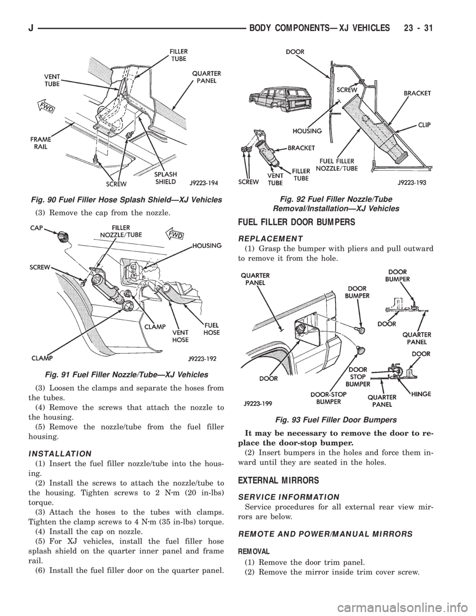
(3) Remove the cap from the nozzle.
(3) Loosen the clamps and separate the hoses from
the tubes.
(4) Remove the screws that attach the nozzle to
the housing.
(5) Remove the nozzle/tube from the fuel filler
housing.
INSTALLATION
(1) Insert the fuel filler nozzle/tube into the hous-
ing.
(2) Install the screws to attach the nozzle/tube to
the housing. Tighten screws to 2 Nzm (20 in-lbs)
torque.
(3) Attach the hoses to the tubes with clamps.
Tighten the clamp screws to 4 Nzm (35 in-lbs) torque.
(4) Install the cap on nozzle.
(5) For XJ vehicles, install the fuel filler hose
splash shield on the quarter inner panel and frame
rail.
(6) Install the fuel filler door on the quarter panel.
FUEL FILLER DOOR BUMPERS
REPLACEMENT
(1) Grasp the bumper with pliers and pull outward
to remove it from the hole.
It may be necessary to remove the door to re-
place the door-stop bumper.
(2) Insert bumpers in the holes and force them in-
ward until they are seated in the holes.
EXTERNAL MIRRORS
SERVICE INFORMATION
Service procedures for all external rear view mir-
rors are below.
REMOTE AND POWER/MANUAL MIRRORS
REMOVAL
(1) Remove the door trim panel.
(2) Remove the mirror inside trim cover screw.
Fig. 90 Fuel Filler Hose Splash ShieldÐXJ Vehicles
Fig. 91 Fuel Filler Nozzle/TubeÐXJ Vehicles
Fig. 92 Fuel Filler Nozzle/Tube
Removal/InstallationÐXJ Vehicles
Fig. 93 Fuel Filler Door Bumpers
JBODY COMPONENTSÐXJ VEHICLES 23 - 31
Page 1488 of 1784
(2) Remove the backing from the double-sided
tape, align each skid strip on the roof, and position it
on the roof panel.
(3) Verify that each skid strip is properly aligned.
(4) Press each skid strip onto the roof panel with a
roller (or use hand pressure).To prevent water leaks, apply 3M Drip-Chek
Sealant, or equivalent.
(5) Position the luggage rack on the roof with the
screw holes aligned.
(6) Install and tighten the slide rail screws to 3
Nzm (28 in-lbs) torque.
Fig. 114 Luggage RackÐXJ VehiclesFig. 115 Skid Strip Installation
JBODY COMPONENTSÐXJ VEHICLES 23 - 33
Page 1494 of 1784
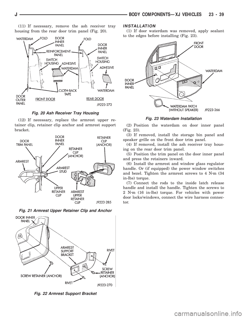
(11) If necessary, remove the ash receiver tray
housing from the rear door trim panel (Fig. 20).
(12) If necessary, replace the armrest upper re-
tainer clip, retainer clip anchor and armrest support
bracket.INSTALLATION
(1) If door waterdam was removed, apply sealant
to the edges before installing (Fig. 23).
(2) Position the waterdam on door inner panel
(Fig. 23).
(3) If removed, install the storage bin panel and
speaker grille on the front door trim panel.
(4) If removed, install the ash receiver tray hous-
ing on the rear door trim panel.
(5) Position the trim panel on the door inner panel
and press the retainers inward.
(6) Install the armrest and window glass regulator
handle. Or (if equipped) the power window switches
and bezel. Tighten the armrest screws to 4 Nzm (34
in-lbs) torque.
(7) Connect the rods to the inside latch release
handle and install the handle. Tighten the screws to
2Nzm (16 in-lbs) torque. For vehicles with power
door locks/windows, connect the wire harness connec-
tor.
Fig. 20 Ash Receiver Tray Housing
Fig. 21 Armrest Upper Retainer Clip and Anchor
Fig. 22 Armrest Support Bracket
Fig. 23 Waterdam Installation
JBODY COMPONENTSÐXJ VEHICLES 23 - 39