1994 JEEP CHEROKEE torque
[x] Cancel search: torquePage 1510 of 1784
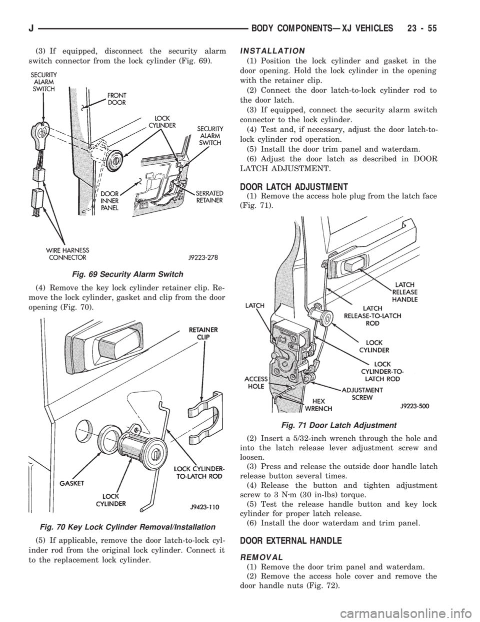
(3) If equipped, disconnect the security alarm
switch connector from the lock cylinder (Fig. 69).
(4) Remove the key lock cylinder retainer clip. Re-
move the lock cylinder, gasket and clip from the door
opening (Fig. 70).
(5) If applicable, remove the door latch-to-lock cyl-
inder rod from the original lock cylinder. Connect it
to the replacement lock cylinder.INSTALLATION
(1) Position the lock cylinder and gasket in the
door opening. Hold the lock cylinder in the opening
with the retainer clip.
(2) Connect the door latch-to-lock cylinder rod to
the door latch.
(3) If equipped, connect the security alarm switch
connector to the lock cylinder.
(4) Test and, if necessary, adjust the door latch-to-
lock cylinder rod operation.
(5) Install the door trim panel and waterdam.
(6) Adjust the door latch as described in DOOR
LATCH ADJUSTMENT.
DOOR LATCH ADJUSTMENT
(1) Remove the access hole plug from the latch face
(Fig. 71).
(2) Insert a 5/32-inch wrench through the hole and
into the latch release lever adjustment screw and
loosen.
(3) Press and release the outside door handle latch
release button several times.
(4) Release the button and tighten adjustment
screw to 3 Nzm (30 in-lbs) torque.
(5) Test the release handle button and key lock
cylinder for proper latch release.
(6) Install the door waterdam and trim panel.
DOOR EXTERNAL HANDLE
REMOVAL
(1) Remove the door trim panel and waterdam.
(2) Remove the access hole cover and remove the
door handle nuts (Fig. 72).
Fig. 71 Door Latch Adjustment
Fig. 69 Security Alarm Switch
Fig. 70 Key Lock Cylinder Removal/Installation
JBODY COMPONENTSÐXJ VEHICLES 23 - 55
Page 1512 of 1784
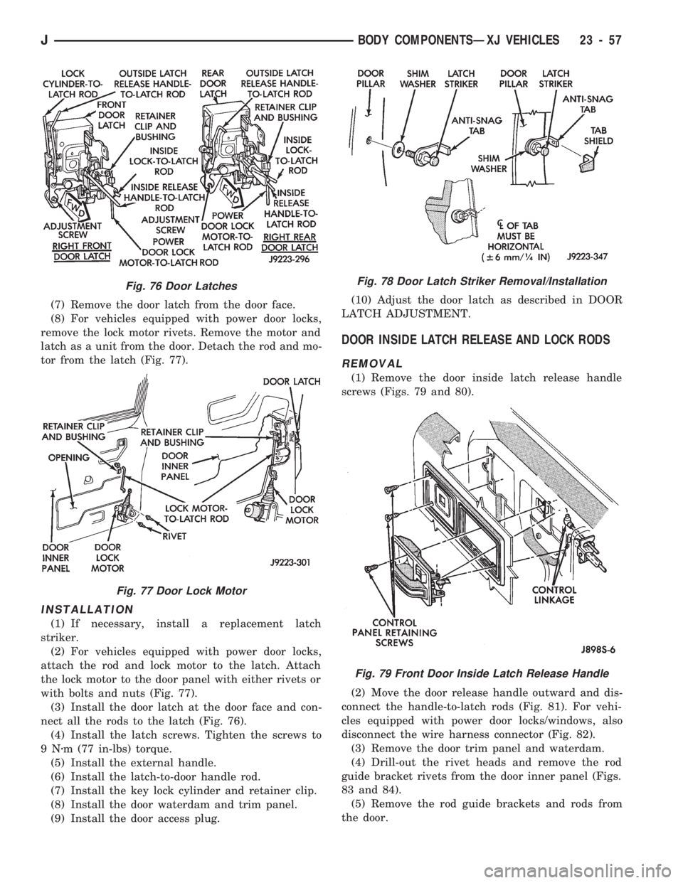
(7) Remove the door latch from the door face.
(8) For vehicles equipped with power door locks,
remove the lock motor rivets. Remove the motor and
latch as a unit from the door. Detach the rod and mo-
tor from the latch (Fig. 77).
INSTALLATION
(1) If necessary, install a replacement latch
striker.
(2) For vehicles equipped with power door locks,
attach the rod and lock motor to the latch. Attach
the lock motor to the door panel with either rivets or
with bolts and nuts (Fig. 77).
(3) Install the door latch at the door face and con-
nect all the rods to the latch (Fig. 76).
(4) Install the latch screws. Tighten the screws to
9Nzm (77 in-lbs) torque.
(5) Install the external handle.
(6) Install the latch-to-door handle rod.
(7) Install the key lock cylinder and retainer clip.
(8) Install the door waterdam and trim panel.
(9) Install the door access plug.(10) Adjust the door latch as described in DOOR
LATCH ADJUSTMENT.
DOOR INSIDE LATCH RELEASE AND LOCK RODS
REMOVAL
(1) Remove the door inside latch release handle
screws (Figs. 79 and 80).
(2) Move the door release handle outward and dis-
connect the handle-to-latch rods (Fig. 81). For vehi-
cles equipped with power door locks/windows, also
disconnect the wire harness connector (Fig. 82).
(3) Remove the door trim panel and waterdam.
(4) Drill-out the rivet heads and remove the rod
guide bracket rivets from the door inner panel (Figs.
83 and 84).
(5) Remove the rod guide brackets and rods from
the door.
Fig. 76 Door Latches
Fig. 77 Door Lock Motor
Fig. 78 Door Latch Striker Removal/Installation
Fig. 79 Front Door Inside Latch Release Handle
JBODY COMPONENTSÐXJ VEHICLES 23 - 57
Page 1516 of 1784
(3) Lower spacer block: install the screws in the
door face. Tighten the screws to 1 Nzm (11 in-lbs)
torque.
DOOR EDGE GUARD/EDGE PROTECTOR STRIP
REPLACEMENT
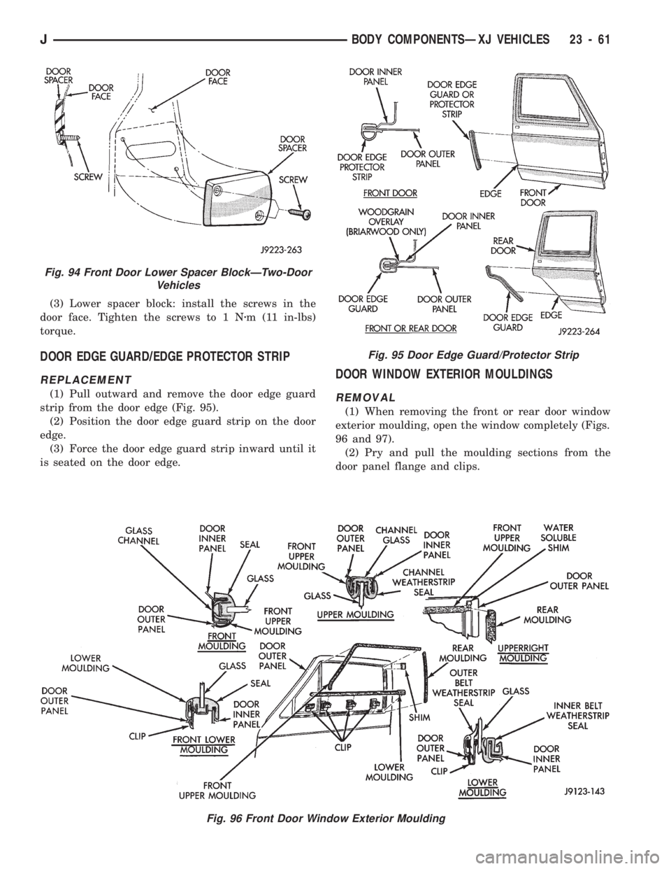
(1) Pull outward and remove the door edge guard
strip from the door edge (Fig. 95).
(2) Position the door edge guard strip on the door
edge.
(3) Force the door edge guard strip inward until it
is seated on the door edge.
DOOR WINDOW EXTERIOR MOULDINGS
REMOVAL
(1) When removing the front or rear door window
exterior moulding, open the window completely (Figs.
96 and 97).
(2) Pry and pull the moulding sections from the
door panel flange and clips.
Fig. 95 Door Edge Guard/Protector Strip
Fig. 96 Front Door Window Exterior Moulding
Fig. 94 Front Door Lower Spacer BlockÐTwo-Door
Vehicles
JBODY COMPONENTSÐXJ VEHICLES 23 - 61
Page 1520 of 1784
LIFTGATE SERVICE INFORMATIONÐXJ VEHICLES
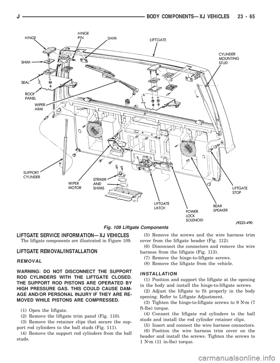
The liftgate components are illustrated in Figure 109.
LIFTGATE REMOVAL/INSTALLATION
REMOVAL
WARNING: DO NOT DISCONNECT THE SUPPORT
ROD CYLINDERS WITH THE LIFTGATE CLOSED.
THE SUPPORT ROD PISTONS ARE OPERATED BY
HIGH PRESSURE GAS. THIS COULD CAUSE DAM-
AGE AND/OR PERSONAL INJURY IF THEY ARE RE-
MOVED WHILE PISTONS ARE COMPRESSED.
(1) Open the liftgate.
(2) Remove the liftgate trim panel (Fig. 110).
(3) Remove the retainer clips that secure the sup-
port rod cylinders to the ball studs (Fig. 111).
(4) Remove the support rod cylinders from the ball
studs.(5) Remove the screws and the wire harness trim
cover from the liftgate header (Fig. 112).
(6) Disconnect the connectors and remove the wire
harness from the liftgate (Fig. 113).
(7) Remove the hinge-to-liftgate screws.
(8) Remove the liftgate from the vehicle.INSTALLATION
(1) Position and support the liftgate at the opening
in the body and install the hinge-to-liftgate screws.
(2) Adjust the liftgate to fit properly in the body
opening. Refer to Liftgate Adjustment.
(3) Tighten the hinge-to-liftgate screws to 9 Nzm(7
ft-lbs) torque.
(4) Connect the liftgate rod cylinders to the ball
studs and install the rod cylinder retainer clips.
(5) Insert and connect the wire harness connectors.
(6) Position the wire harness trim cover on the
header and install the screws. Tighten the screws to
1Nzm (11 in-lbs) torque.
Fig. 109 Liftgate Components
JBODY COMPONENTSÐXJ VEHICLES 23 - 65
Page 1522 of 1784
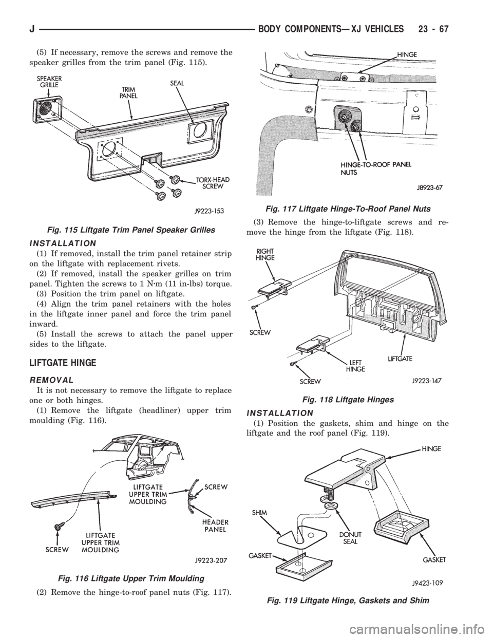
(5) If necessary, remove the screws and remove the
speaker grilles from the trim panel (Fig. 115).
INSTALLATION
(1) If removed, install the trim panel retainer strip
on the liftgate with replacement rivets.
(2) If removed, install the speaker grilles on trim
panel. Tighten the screws to 1 Nzm (11 in-lbs) torque.
(3) Position the trim panel on liftgate.
(4) Align the trim panel retainers with the holes
in the liftgate inner panel and force the trim panel
inward.
(5) Install the screws to attach the panel upper
sides to the liftgate.
LIFTGATE HINGE
REMOVAL
It is not necessary to remove the liftgate to replace
one or both hinges.
(1) Remove the liftgate (headliner) upper trim
moulding (Fig. 116).
(2) Remove the hinge-to-roof panel nuts (Fig. 117).(3) Remove the hinge-to-liftgate screws and re-
move the hinge from the liftgate (Fig. 118).
INSTALLATION
(1) Position the gaskets, shim and hinge on the
liftgate and the roof panel (Fig. 119).
Fig. 115 Liftgate Trim Panel Speaker Grilles
Fig. 116 Liftgate Upper Trim Moulding
Fig. 117 Liftgate Hinge-To-Roof Panel Nuts
Fig. 118 Liftgate Hinges
Fig. 119 Liftgate Hinge, Gaskets and Shim
JBODY COMPONENTSÐXJ VEHICLES 23 - 67
Page 1523 of 1784
(2) Install and tighten hinge-to-roof panel nuts to 9
Nzm (7 ft-lbs) torque.
(3) Install the liftgate-to-hinge screws. Tighten
screws to 9 Nzm (7 ft-lbs) torque.
(4) Install the liftgate (headliner) upper trim moul-
ding (Fig. 111).
LIFTGATE LATCH/KEY LOCK CYLINDER/STRIKER
REMOVAL
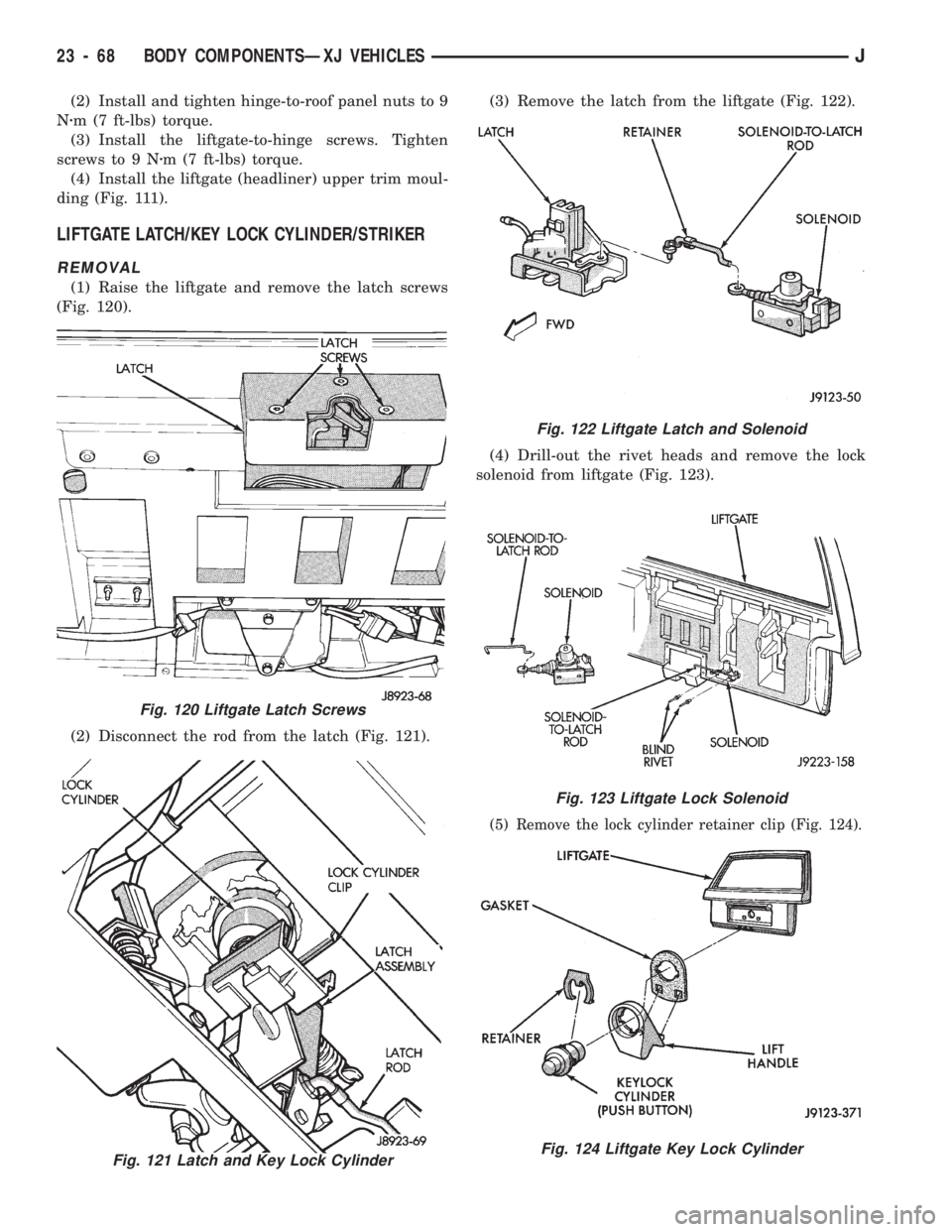
(1) Raise the liftgate and remove the latch screws
(Fig. 120).
(2) Disconnect the rod from the latch (Fig. 121).(3) Remove the latch from the liftgate (Fig. 122).
(4) Drill-out the rivet heads and remove the lock
solenoid from liftgate (Fig. 123).
(5) Remove the lock cylinder retainer clip (Fig. 124).
Fig. 121 Latch and Key Lock Cylinder
Fig. 122 Liftgate Latch and Solenoid
Fig. 123 Liftgate Lock Solenoid
Fig. 124 Liftgate Key Lock Cylinder
Fig. 120 Liftgate Latch Screws
23 - 68 BODY COMPONENTSÐXJ VEHICLESJ
Page 1524 of 1784
(6) Remove the key lock cylinder.
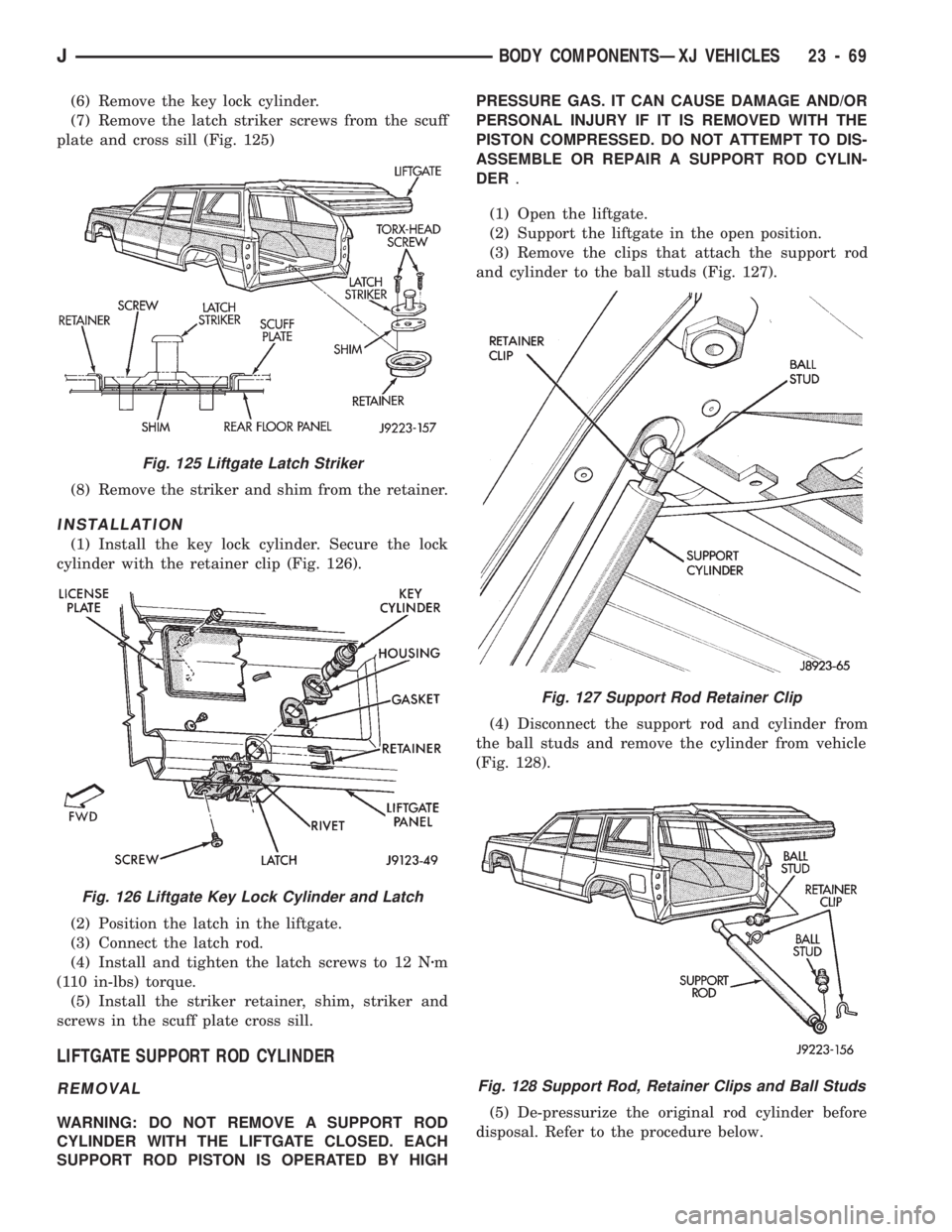
(7) Remove the latch striker screws from the scuff
plate and cross sill (Fig. 125)
(8) Remove the striker and shim from the retainer.
INSTALLATION
(1) Install the key lock cylinder. Secure the lock
cylinder with the retainer clip (Fig. 126).
(2) Position the latch in the liftgate.
(3) Connect the latch rod.
(4) Install and tighten the latch screws to 12 Nzm
(110 in-lbs) torque.
(5) Install the striker retainer, shim, striker and
screws in the scuff plate cross sill.
LIFTGATE SUPPORT ROD CYLINDER
REMOVAL
WARNING: DO NOT REMOVE A SUPPORT ROD
CYLINDER WITH THE LIFTGATE CLOSED. EACH
SUPPORT ROD PISTON IS OPERATED BY HIGHPRESSURE GAS. IT CAN CAUSE DAMAGE AND/OR
PERSONAL INJURY IF IT IS REMOVED WITH THE
PISTON COMPRESSED. DO NOT ATTEMPT TO DIS-
ASSEMBLE OR REPAIR A SUPPORT ROD CYLIN-
DER.
(1) Open the liftgate.
(2) Support the liftgate in the open position.
(3) Remove the clips that attach the support rod
and cylinder to the ball studs (Fig. 127).
(4) Disconnect the support rod and cylinder from
the ball studs and remove the cylinder from vehicle
(Fig. 128).
(5) De-pressurize the original rod cylinder before
disposal. Refer to the procedure below.
Fig. 127 Support Rod Retainer Clip
Fig. 128 Support Rod, Retainer Clips and Ball Studs
Fig. 125 Liftgate Latch Striker
Fig. 126 Liftgate Key Lock Cylinder and Latch
JBODY COMPONENTSÐXJ VEHICLES 23 - 69
Page 1525 of 1784
INSTALLATION
(1) Connect the replacement support rod and cylin-
der to the ball studs.
(2) Secure the support rod and cylinder to the ball
studs with the retainer clips.
(3) Remove the support from the liftgate and test
the operation of the support rod.
LIFTGATE SUPPORT ROD CYLINDER DISPOSAL
WARNING: SAFETY GOGGLES MUST BE WORN
DURING THE DISPOSAL PROCEDURE. THE HIGH
PRESSURE GAS CHARGE IN THE SUPPORT ROD
CYLINDERS WILL BE RELEASED DURING THE
PROCEDURE.
(1) Remove the support rod cylinder(s) from the
liftgate.
(2) Position the support rod cylinder horizontally
in a vise and clamp the cylinder securely.
(3) Wrap the cylinder with 4-5 layers of shop tow-
els.
(4) Measure 1 and 1/2 inches inward from the end
of the cylinder. Mark this location on the towels with
chalk. The cylinder will be punctured at this location
to release the gas charge.
(5) Use a punch and hammer to puncture cylinder.
Force the punch through towels and into the cylinder
with a hammer. Continue striking the punch until
the gas begins to escapebut do not remove the
punch.
(6) Hold the towels and punch in position until all
the gas has escaped. Complete de-pressurization will
require about 4 to 10 seconds. After all the gas has
escaped, slowly remove the punch.
(7) Hold a towel over the hole in cylinder and press
the support rod piston all the way into the cylinder
to purge remaining oil.
(8) Remove the support rod cylinder from the vise
and discard it.
(9) If both support rod cylinders are being re-
placed, repeat this procedure for the remaining cylin-
der.
LIFTGATE SUPPORT ROD BALL STUD
REPLACEMENT
REMOVAL
(1) Open the liftgate.
(2) Support the liftgate in the open position.
(3) Remove the retainer clip that attaches the sup-
port rod and cylinder to the ball stud.
(4) Disconnect the support rod from the ball stud.
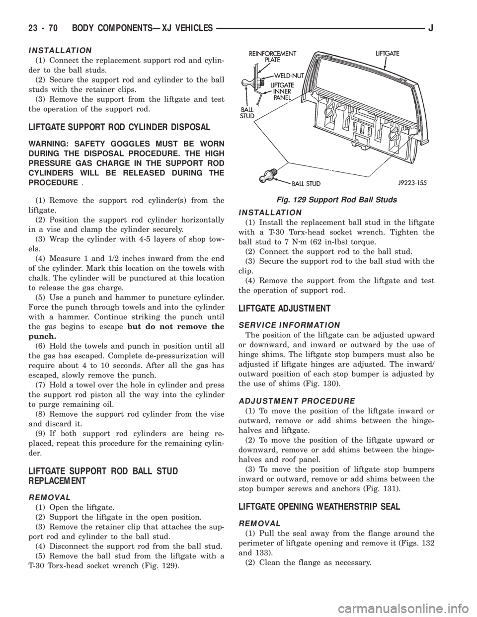
(5) Remove the ball stud from the liftgate with a
T-30 Torx-head socket wrench (Fig. 129).
INSTALLATION
(1) Install the replacement ball stud in the liftgate
with a T-30 Torx-head socket wrench. Tighten the
ball stud to 7 Nzm (62 in-lbs) torque.
(2) Connect the support rod to the ball stud.
(3) Secure the support rod to the ball stud with the
clip.
(4) Remove the support from the liftgate and test
the operation of support rod.
LIFTGATE ADJUSTMENT
SERVICE INFORMATION
The position of the liftgate can be adjusted upward
or downward, and inward or outward by the use of
hinge shims. The liftgate stop bumpers must also be
adjusted if liftgate hinges are adjusted. The inward/
outward position of each stop bumper is adjusted by
the use of shims (Fig. 130).
ADJUSTMENT PROCEDURE
(1) To move the position of the liftgate inward or
outward, remove or add shims between the hinge-
halves and liftgate.
(2) To move the position of the liftgate upward or
downward, remove or add shims between the hinge-
halves and roof panel.
(3) To move the position of liftgate stop bumpers
inward or outward, remove or add shims between the
stop bumper screws and anchors (Fig. 131).
LIFTGATE OPENING WEATHERSTRIP SEAL
REMOVAL
(1) Pull the seal away from the flange around the
perimeter of liftgate opening and remove it (Figs. 132
and 133).
(2) Clean the flange as necessary.
Fig. 129 Support Rod Ball Studs
23 - 70 BODY COMPONENTSÐXJ VEHICLESJ