1994 JEEP CHEROKEE torque
[x] Cancel search: torquePage 1569 of 1784
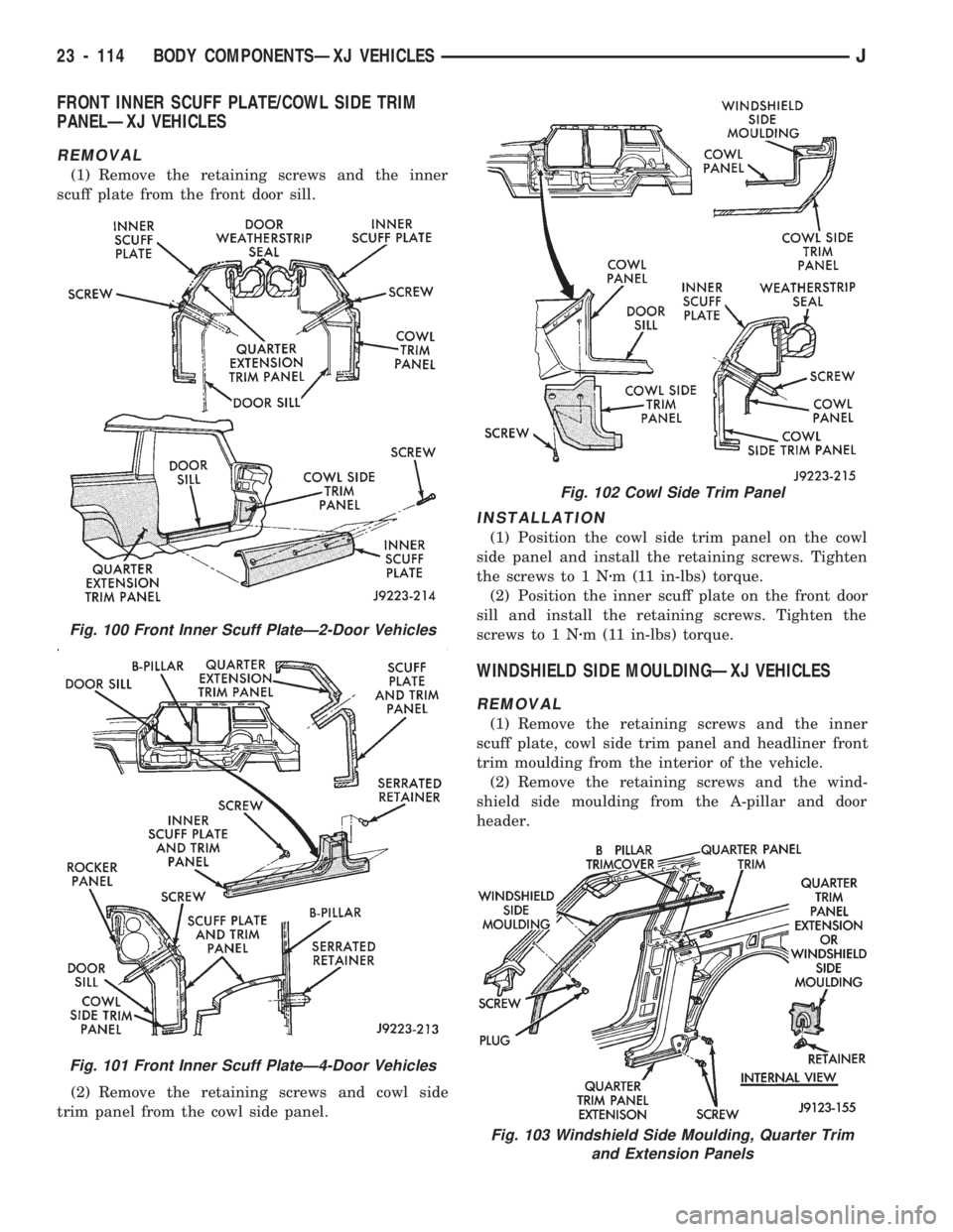
FRONT INNER SCUFF PLATE/COWL SIDE TRIM
PANELÐXJ VEHICLES
REMOVAL
(1) Remove the retaining screws and the inner
scuff plate from the front door sill.
(2) Remove the retaining screws and cowl side
trim panel from the cowl side panel.
INSTALLATION
(1) Position the cowl side trim panel on the cowl
side panel and install the retaining screws. Tighten
the screws to 1 Nzm (11 in-lbs) torque.
(2) Position the inner scuff plate on the front door
sill and install the retaining screws. Tighten the
screws to 1 Nzm (11 in-lbs) torque.
WINDSHIELD SIDE MOULDINGÐXJ VEHICLES
REMOVAL
(1) Remove the retaining screws and the inner
scuff plate, cowl side trim panel and headliner front
trim moulding from the interior of the vehicle.
(2) Remove the retaining screws and the wind-
shield side moulding from the A-pillar and door
header.
Fig. 100 Front Inner Scuff PlateÐ2-Door Vehicles
Fig. 101 Front Inner Scuff PlateÐ4-Door Vehicles
Fig. 102 Cowl Side Trim Panel
Fig. 103 Windshield Side Moulding, Quarter Trim
and Extension Panels
23 - 114 BODY COMPONENTSÐXJ VEHICLESJ
Page 1570 of 1784
INSTALLATION
(1) Position the windshield side moulding on the A-
pillar and door header. Install the retaining screws
and tighten to 1 Nzm (11 in-lbs) torque.
(2) Install the headliner front trim moulding, the
cowl side trim panel and the inner scuff plate in the
interior of the vehicle. Tighten the retaining screw to
1Nzm (11 in-lbs) torque.
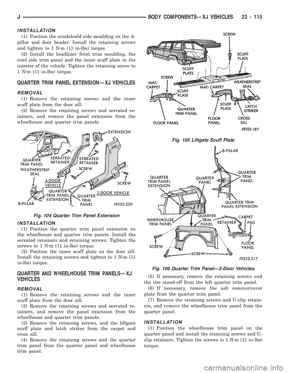
QUARTER TRIM PANEL EXTENSIONÐXJ VEHICLES
REMOVAL
(1) Remove the retaining screws and the inner
scuff plate from the door sill.
(2) Remove the retaining screws and serrated re-
tainers, and remove the panel extension from the
wheelhouse and quarter trim panels.
INSTALLATION
(1) Position the quarter trim panel extension on
the wheelhouse and quarter trim panels. Install the
serrated retainers and retaining screws. Tighten the
screws to 1 Nzm (11 in-lbs) torque.
(2) Position the inner scuff plate on the door sill.
Install the retaining screws and tighten to 1 Nzm(11
in-lbs) torque.
QUARTER AND WHEELHOUSE TRIM PANELSÐXJ
VEHICLES
REMOVAL
(1) Remove the retaining screws and the inner
scuff plate from the door sill.
(2) Remove the retaining screws and serrated re-
tainers, and remove the panel extension from the
wheelhouse and quarter trim panels.
(3) Remove the retaining screws, and the liftgate
scuff plate and latch striker from the carpet and
cross sill.
(4) Remove the retaining screws and the quarter
trim panel from the quarter panel and wheelhouse
trim panel.(5) If necessary, remove the retaining screws and
the tire stand-off from the left quarter trim panel.
(6) If necessary, remove the ash receiver/cover
plate from the quarter trim panel.
(7) Remove the retaining screws and U-clip retain-
ers, and remove the wheelhouse trim panel from the
quarter panel.
INSTALLATION
(1) Position the wheelhouse trim panel on the
quarter panel and install the retaining screws and U-
clip retainers. Tighten the screws to 1 Nzm (11 in-lbs)
torque.
Fig. 105 Liftgate Scuff Plate
Fig. 106 Quarter Trim PanelÐ2-Door Vehicles
Fig. 104 Quarter Trim Panel Extension
JBODY COMPONENTSÐXJ VEHICLES 23 - 115
Page 1571 of 1784
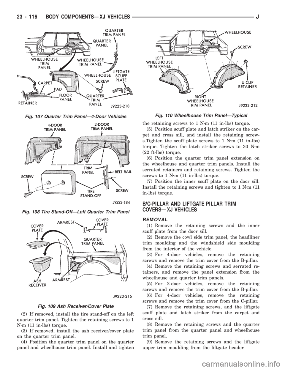
(2) If removed, install the tire stand-off on the left
quarter trim panel. Tighten the retaining screws to 1
Nzm (11 in-lbs) torque.
(3) If removed, install the ash receiver/cover plate
on the quarter trim panel.
(4) Position the quarter trim panel on the quarter
panel and wheelhouse trim panel. Install and tightenthe retaining screws to 1 Nzm (11 in-lbs) torque.
(5) Position scuff plate and latch striker on the car-
pet and cross sill, and install the retaining screw-
s.Tighten the scuff plate screws to 1 Nzm (11 in-lbs)
torque. Tighten the latch striker screws to 30 Nzm
(22 ft-lbs) torque.
(6) Position the quarter trim panel extension on
the wheelhouse and quarter trim panels. Install the
serrated retainers and retaining screws. Tighten the
screws to 1 Nzm (11 in-lbs) torque.
(7) Position the inner scuff plate on the door sill.
Install the retaining screws and tighten to 1 Nzm(11
in-lbs) torque.
B/C-PILLAR AND LIFTGATE PILLAR TRIM
COVERSÐXJ VEHICLES
REMOVAL
(1) Remove the retaining screws and the inner
scuff plate from the door sill.
(2) Remove the cowl side trim panel, the headliner
trim moulding and the windshield side moulding
from the interior of the vehicle.
(3) For 4-door vehicles, remove the retaining
screws and remove the trim cover from the B-pillar.
(4) Remove the retaining screws and serrated re-
tainers, and remove the panel extension from the
wheelhouse and quarter trim panels.
(5) For 2-door vehicles, remove the retaining
screws and remove the trim cover from the B-pillar.
(6) For 4-door vehicles, remove the retaining
screws and remove the trim cover from the C-pillar.
(7) Remove the retaining screws, and the liftgate
scuff plate and latch striker from the carpet and
cross sill.
(8) Remove the retaining screws and the quarter
trim panel from the quarter panel and wheelhouse
trim panel.
(9) Remove the retaining screws and the liftgate
upper trim moulding from the liftgate header.
Fig. 107 Quarter Trim PanelÐ4-Door Vehicles
Fig. 108 Tire Stand-OffÐLeft Quarter Trim Panel
Fig. 109 Ash Receiver/Cover Plate
Fig. 110 Wheelhouse Trim PanelÐTypical
23 - 116 BODY COMPONENTSÐXJ VEHICLESJ
Page 1572 of 1784
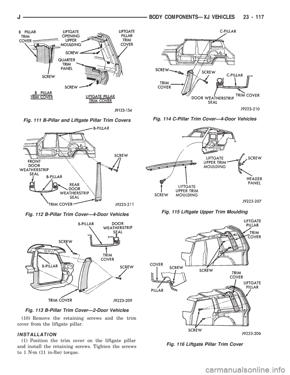
(10) Remove the retaining screws and the trim
cover from the liftgate pillar.
INSTALLATION
(1) Position the trim cover on the liftgate pillar
and install the retaining screws. Tighten the screws
to1Nzm (11 in-lbs) torque.
Fig. 111 B-Pillar and Liftgate Pillar Trim Covers
Fig. 112 B-Pillar Trim CoverÐ4-Door Vehicles
Fig. 113 B-Pillar Trim CoverÐ2-Door Vehicles
Fig. 114 C-Pillar Trim CoverÐ4-Door Vehicles
Fig. 115 Liftgate Upper Trim Moulding
Fig. 116 Liftgate Pillar Trim Cover
JBODY COMPONENTSÐXJ VEHICLES 23 - 117
Page 1573 of 1784
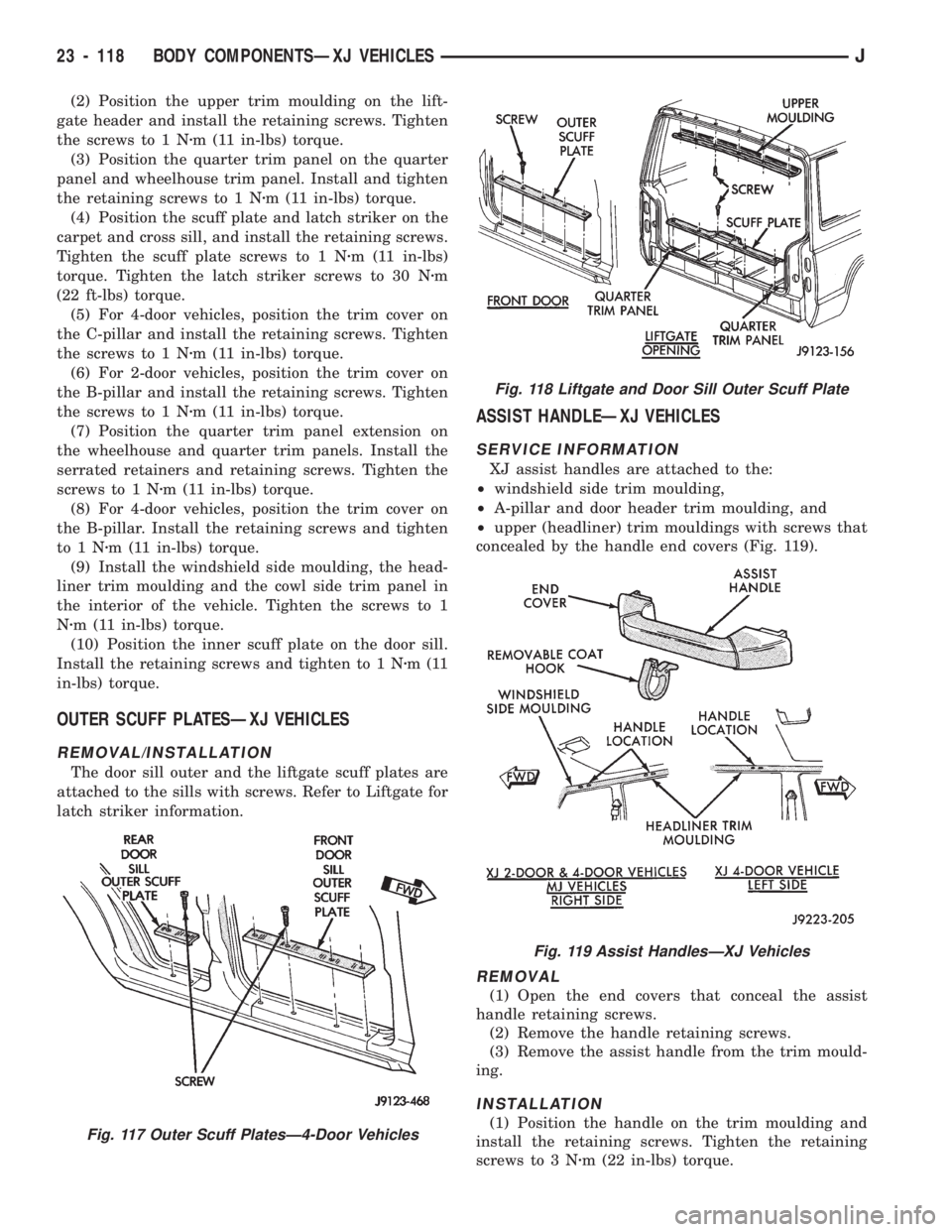
(2) Position the upper trim moulding on the lift-
gate header and install the retaining screws. Tighten
the screws to 1 Nzm (11 in-lbs) torque.
(3) Position the quarter trim panel on the quarter
panel and wheelhouse trim panel. Install and tighten
the retaining screws to 1 Nzm (11 in-lbs) torque.
(4) Position the scuff plate and latch striker on the
carpet and cross sill, and install the retaining screws.
Tighten the scuff plate screws to 1 Nzm (11 in-lbs)
torque. Tighten the latch striker screws to 30 Nzm
(22 ft-lbs) torque.
(5) For 4-door vehicles, position the trim cover on
the C-pillar and install the retaining screws. Tighten
the screws to 1 Nzm (11 in-lbs) torque.
(6) For 2-door vehicles, position the trim cover on
the B-pillar and install the retaining screws. Tighten
the screws to 1 Nzm (11 in-lbs) torque.
(7) Position the quarter trim panel extension on
the wheelhouse and quarter trim panels. Install the
serrated retainers and retaining screws. Tighten the
screws to 1 Nzm (11 in-lbs) torque.
(8) For 4-door vehicles, position the trim cover on
the B-pillar. Install the retaining screws and tighten
to1Nzm (11 in-lbs) torque.
(9) Install the windshield side moulding, the head-
liner trim moulding and the cowl side trim panel in
the interior of the vehicle. Tighten the screws to 1
Nzm (11 in-lbs) torque.
(10) Position the inner scuff plate on the door sill.
Install the retaining screws and tighten to 1 Nzm(11
in-lbs) torque.
OUTER SCUFF PLATESÐXJ VEHICLES
REMOVAL/INSTALLATION
The door sill outer and the liftgate scuff plates are
attached to the sills with screws. Refer to Liftgate for
latch striker information.
ASSIST HANDLEÐXJ VEHICLES
SERVICE INFORMATION
XJ assist handles are attached to the:
²windshield side trim moulding,
²A-pillar and door header trim moulding, and
²upper (headliner) trim mouldings with screws that
concealed by the handle end covers (Fig. 119).
REMOVAL
(1) Open the end covers that conceal the assist
handle retaining screws.
(2) Remove the handle retaining screws.
(3) Remove the assist handle from the trim mould-
ing.
INSTALLATION
(1) Position the handle on the trim moulding and
install the retaining screws. Tighten the retaining
screws to 3 Nzm (22 in-lbs) torque.Fig. 117 Outer Scuff PlatesÐ4-Door Vehicles
Fig. 118 Liftgate and Door Sill Outer Scuff Plate
Fig. 119 Assist HandlesÐXJ Vehicles
23 - 118 BODY COMPONENTSÐXJ VEHICLESJ
Page 1574 of 1784
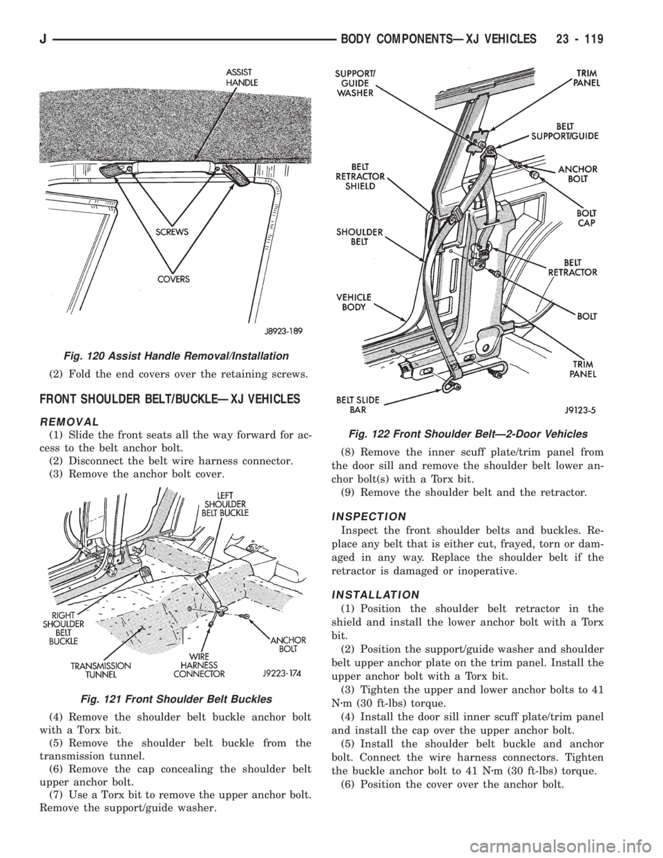
(2) Fold the end covers over the retaining screws.
FRONT SHOULDER BELT/BUCKLEÐXJ VEHICLES
REMOVAL
(1) Slide the front seats all the way forward for ac-
cess to the belt anchor bolt.
(2) Disconnect the belt wire harness connector.
(3) Remove the anchor bolt cover.
(4) Remove the shoulder belt buckle anchor bolt
with a Torx bit.
(5) Remove the shoulder belt buckle from the
transmission tunnel.
(6) Remove the cap concealing the shoulder belt
upper anchor bolt.
(7) Use a Torx bit to remove the upper anchor bolt.
Remove the support/guide washer.(8) Remove the inner scuff plate/trim panel from
the door sill and remove the shoulder belt lower an-
chor bolt(s) with a Torx bit.
(9) Remove the shoulder belt and the retractor.
INSPECTION
Inspect the front shoulder belts and buckles. Re-
place any belt that is either cut, frayed, torn or dam-
aged in any way. Replace the shoulder belt if the
retractor is damaged or inoperative.
INSTALLATION
(1) Position the shoulder belt retractor in the
shield and install the lower anchor bolt with a Torx
bit.
(2) Position the support/guide washer and shoulder
belt upper anchor plate on the trim panel. Install the
upper anchor bolt with a Torx bit.
(3) Tighten the upper and lower anchor bolts to 41
Nzm (30 ft-lbs) torque.
(4) Install the door sill inner scuff plate/trim panel
and install the cap over the upper anchor bolt.
(5) Install the shoulder belt buckle and anchor
bolt. Connect the wire harness connectors. Tighten
the buckle anchor bolt to 41 Nzm (30 ft-lbs) torque.
(6) Position the cover over the anchor bolt.
Fig. 120 Assist Handle Removal/Installation
Fig. 121 Front Shoulder Belt Buckles
Fig. 122 Front Shoulder BeltÐ2-Door Vehicles
JBODY COMPONENTSÐXJ VEHICLES 23 - 119
Page 1575 of 1784
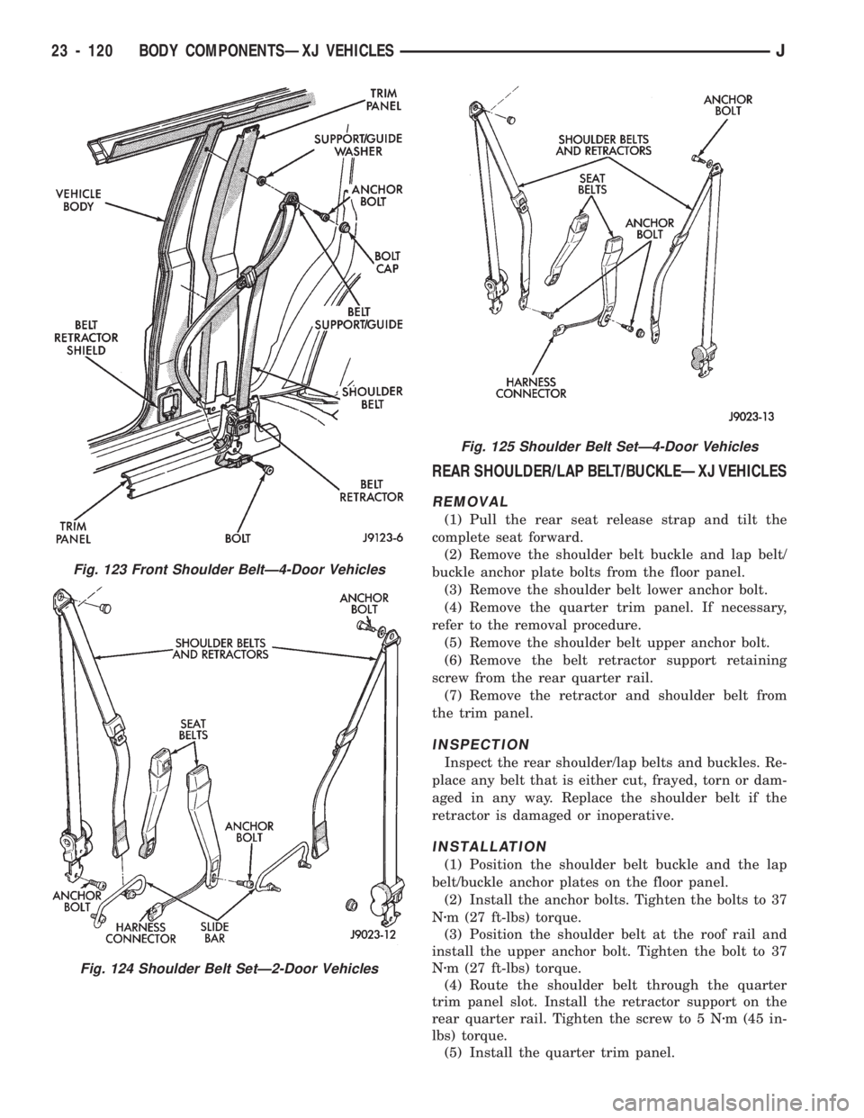
REAR SHOULDER/LAP BELT/BUCKLEÐXJ VEHICLES
REMOVAL
(1) Pull the rear seat release strap and tilt the
complete seat forward.
(2) Remove the shoulder belt buckle and lap belt/
buckle anchor plate bolts from the floor panel.
(3) Remove the shoulder belt lower anchor bolt.
(4) Remove the quarter trim panel. If necessary,
refer to the removal procedure.
(5) Remove the shoulder belt upper anchor bolt.
(6) Remove the belt retractor support retaining
screw from the rear quarter rail.
(7) Remove the retractor and shoulder belt from
the trim panel.
INSPECTION
Inspect the rear shoulder/lap belts and buckles. Re-
place any belt that is either cut, frayed, torn or dam-
aged in any way. Replace the shoulder belt if the
retractor is damaged or inoperative.
INSTALLATION
(1) Position the shoulder belt buckle and the lap
belt/buckle anchor plates on the floor panel.
(2) Install the anchor bolts. Tighten the bolts to 37
Nzm (27 ft-lbs) torque.
(3) Position the shoulder belt at the roof rail and
install the upper anchor bolt. Tighten the bolt to 37
Nzm (27 ft-lbs) torque.
(4) Route the shoulder belt through the quarter
trim panel slot. Install the retractor support on the
rear quarter rail. Tighten the screw to 5 Nzm (45 in-
lbs) torque.
(5) Install the quarter trim panel.
Fig. 123 Front Shoulder BeltÐ4-Door Vehicles
Fig. 124 Shoulder Belt SetÐ2-Door Vehicles
Fig. 125 Shoulder Belt SetÐ4-Door Vehicles
23 - 120 BODY COMPONENTSÐXJ VEHICLESJ
Page 1576 of 1784
(6) Install the shoulder belt lower anchor bolt.
Tighten the bolt to 37 Nzm (27 ft-lbs) torque.
(7) Return the rear seat to the normal position and
engage the latch.
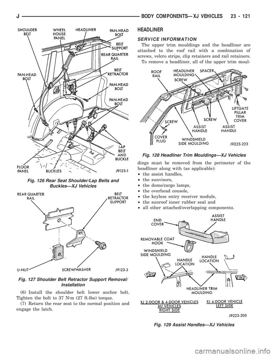
HEADLINER
SERVICE INFORMATION
The upper trim mouldings and the headliner are
attached to the roof rail with a combination of
screws, velcro strips, clip retainers and rail retainers.
To remove a headliner, all of the upper trim moul-
dings must be removed from the perimeter of the
headliner along with (as applicable):
²the assist handles,
²the sunvisors,
²the dome/cargo lamps,
²the overhead console,
²the keyless entry receiver module,
²the sunroof inner rubber seal and
²all other attached/overlapping components.
Fig. 128 Headliner Trim MouldingsÐXJ Vehicles
Fig. 129 Assist HandlesÐXJ Vehicles
Fig. 126 Rear Seat Shoulder/Lap Belts and
BucklesÐXJ Vehicles
Fig. 127 Shoulder Belt Retractor Support Removal/
Installation
JBODY COMPONENTSÐXJ VEHICLES 23 - 121