1994 JEEP CHEROKEE torque
[x] Cancel search: torquePage 1608 of 1784
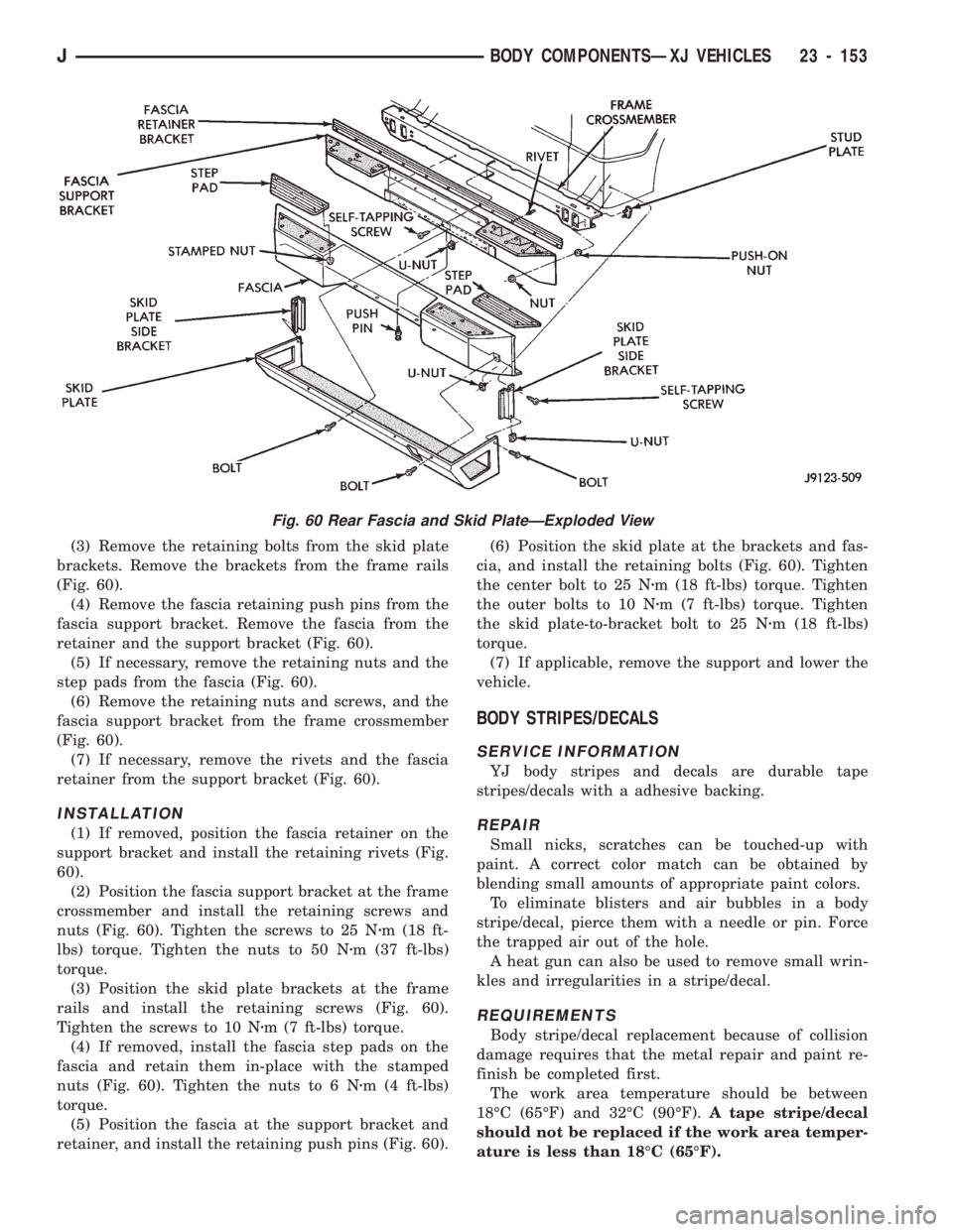
(3) Remove the retaining bolts from the skid plate
brackets. Remove the brackets from the frame rails
(Fig. 60).
(4) Remove the fascia retaining push pins from the
fascia support bracket. Remove the fascia from the
retainer and the support bracket (Fig. 60).
(5) If necessary, remove the retaining nuts and the
step pads from the fascia (Fig. 60).
(6) Remove the retaining nuts and screws, and the
fascia support bracket from the frame crossmember
(Fig. 60).
(7) If necessary, remove the rivets and the fascia
retainer from the support bracket (Fig. 60).
INSTALLATION
(1) If removed, position the fascia retainer on the
support bracket and install the retaining rivets (Fig.
60).
(2) Position the fascia support bracket at the frame
crossmember and install the retaining screws and
nuts (Fig. 60). Tighten the screws to 25 Nzm (18 ft-
lbs) torque. Tighten the nuts to 50 Nzm (37 ft-lbs)
torque.
(3) Position the skid plate brackets at the frame
rails and install the retaining screws (Fig. 60).
Tighten the screws to 10 Nzm (7 ft-lbs) torque.
(4) If removed, install the fascia step pads on the
fascia and retain them in-place with the stamped
nuts (Fig. 60). Tighten the nuts to 6 Nzm (4 ft-lbs)
torque.
(5) Position the fascia at the support bracket and
retainer, and install the retaining push pins (Fig. 60).(6) Position the skid plate at the brackets and fas-
cia, and install the retaining bolts (Fig. 60). Tighten
the center bolt to 25 Nzm (18 ft-lbs) torque. Tighten
the outer bolts to 10 Nzm (7 ft-lbs) torque. Tighten
the skid plate-to-bracket bolt to 25 Nzm (18 ft-lbs)
torque.
(7) If applicable, remove the support and lower the
vehicle.
BODY STRIPES/DECALS
SERVICE INFORMATION
YJ body stripes and decals are durable tape
stripes/decals with a adhesive backing.
REPAIR
Small nicks, scratches can be touched-up with
paint. A correct color match can be obtained by
blending small amounts of appropriate paint colors.
To eliminate blisters and air bubbles in a body
stripe/decal, pierce them with a needle or pin. Force
the trapped air out of the hole.
A heat gun can also be used to remove small wrin-
kles and irregularities in a stripe/decal.
REQUIREMENTS
Body stripe/decal replacement because of collision
damage requires that the metal repair and paint re-
finish be completed first.
The work area temperature should be between
18ÉC (65ÉF) and 32ÉC (90ÉF).A tape stripe/decal
should not be replaced if the work area temper-
ature is less than 18ÉC (65ÉF).
Fig. 60 Rear Fascia and Skid PlateÐExploded View
JBODY COMPONENTSÐXJ VEHICLES 23 - 153
Page 1613 of 1784
area and re-align stripe/decal with panel character
line.Do not lift the tape stripe/decal if only a
few air bubbles exist.
(10) Where applicable, allow 12 mm (1/2 in) extra
tape stripe/decal to extend beyond the edges to be
folded over.
(11) Fold the excess tape stripe/decal back onto in-
side flange area.Use care to avoid trapping air
under the tape stripe/decal.Where necessary,
trim excess tape stripe/decal.
(12) Inspect tape installation with reflected light to
detect any defects that could have developed during
the installation.
(13) Remove all air and moisture bubbles from the
tape stripe/decal with a needle or pin.
(14) Install any removed components and clean the
vehicle as necessary.
EXTERIOR NAMEPLATES (ADHESIVE-BACKED)
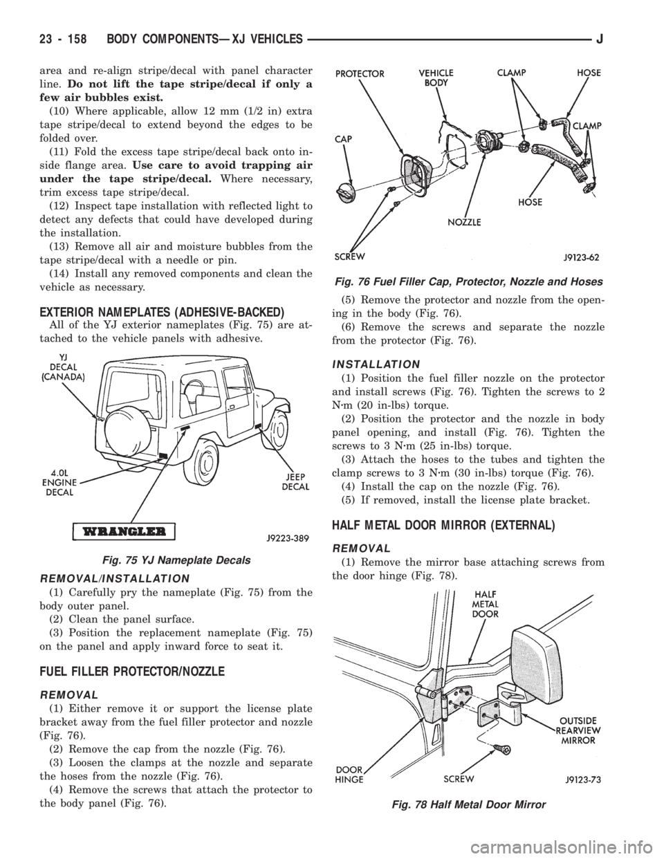
All of the YJ exterior nameplates (Fig. 75) are at-
tached to the vehicle panels with adhesive.
REMOVAL/INSTALLATION
(1) Carefully pry the nameplate (Fig. 75) from the
body outer panel.
(2) Clean the panel surface.
(3) Position the replacement nameplate (Fig. 75)
on the panel and apply inward force to seat it.
FUEL FILLER PROTECTOR/NOZZLE
REMOVAL
(1) Either remove it or support the license plate
bracket away from the fuel filler protector and nozzle
(Fig. 76).
(2) Remove the cap from the nozzle (Fig. 76).
(3) Loosen the clamps at the nozzle and separate
the hoses from the nozzle (Fig. 76).
(4) Remove the screws that attach the protector to
the body panel (Fig. 76).(5) Remove the protector and nozzle from the open-
ing in the body (Fig. 76).
(6) Remove the screws and separate the nozzle
from the protector (Fig. 76).
INSTALLATION
(1) Position the fuel filler nozzle on the protector
and install screws (Fig. 76). Tighten the screws to 2
Nzm (20 in-lbs) torque.
(2) Position the protector and the nozzle in body
panel opening, and install (Fig. 76). Tighten the
screws to 3 Nzm (25 in-lbs) torque.
(3) Attach the hoses to the tubes and tighten the
clamp screws to 3 Nzm (30 in-lbs) torque (Fig. 76).
(4) Install the cap on the nozzle (Fig. 76).
(5) If removed, install the license plate bracket.
HALF METAL DOOR MIRROR (EXTERNAL)
REMOVAL
(1) Remove the mirror base attaching screws from
the door hinge (Fig. 78).
Fig. 76 Fuel Filler Cap, Protector, Nozzle and Hoses
Fig. 78 Half Metal Door Mirror
Fig. 75 YJ Nameplate Decals
23 - 158 BODY COMPONENTSÐXJ VEHICLESJ
Page 1614 of 1784
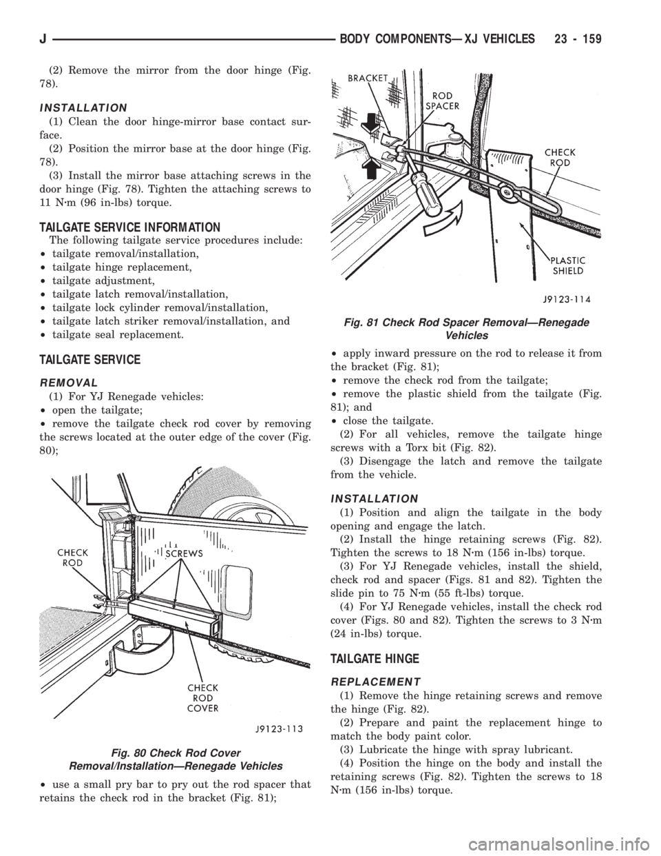
(2) Remove the mirror from the door hinge (Fig.
78).
INSTALLATION
(1) Clean the door hinge-mirror base contact sur-
face.
(2) Position the mirror base at the door hinge (Fig.
78).
(3) Install the mirror base attaching screws in the
door hinge (Fig. 78). Tighten the attaching screws to
11 Nzm (96 in-lbs) torque.
TAILGATE SERVICE INFORMATION
The following tailgate service procedures include:
²tailgate removal/installation,
²tailgate hinge replacement,
²tailgate adjustment,
²tailgate latch removal/installation,
²tailgate lock cylinder removal/installation,
²tailgate latch striker removal/installation, and
²tailgate seal replacement.
TAILGATE SERVICE
REMOVAL
(1) For YJ Renegade vehicles:
²open the tailgate;
²remove the tailgate check rod cover by removing
the screws located at the outer edge of the cover (Fig.
80);
²use a small pry bar to pry out the rod spacer that
retains the check rod in the bracket (Fig. 81);²apply inward pressure on the rod to release it from
the bracket (Fig. 81);
²remove the check rod from the tailgate;
²remove the plastic shield from the tailgate (Fig.
81); and
²close the tailgate.
(2) For all vehicles, remove the tailgate hinge
screws with a Torx bit (Fig. 82).
(3) Disengage the latch and remove the tailgate
from the vehicle.
INSTALLATION
(1) Position and align the tailgate in the body
opening and engage the latch.
(2) Install the hinge retaining screws (Fig. 82).
Tighten the screws to 18 Nzm (156 in-lbs) torque.
(3) For YJ Renegade vehicles, install the shield,
check rod and spacer (Figs. 81 and 82). Tighten the
slide pin to 75 Nzm (55 ft-lbs) torque.
(4) For YJ Renegade vehicles, install the check rod
cover (Figs. 80 and 82). Tighten the screws to 3 Nzm
(24 in-lbs) torque.
TAILGATE HINGE
REPLACEMENT
(1) Remove the hinge retaining screws and remove
the hinge (Fig. 82).
(2) Prepare and paint the replacement hinge to
match the body paint color.
(3) Lubricate the hinge with spray lubricant.
(4) Position the hinge on the body and install the
retaining screws (Fig. 82). Tighten the screws to 18
Nzm (156 in-lbs) torque.
Fig. 80 Check Rod Cover
Removal/InstallationÐRenegade Vehicles
Fig. 81 Check Rod Spacer RemovalÐRenegade
Vehicles
JBODY COMPONENTSÐXJ VEHICLES 23 - 159
Page 1615 of 1784
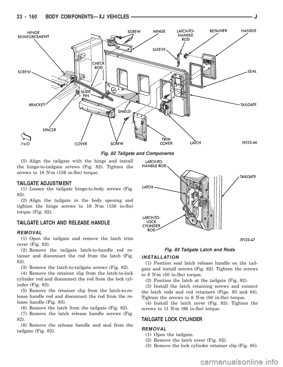
(5) Align the tailgate with the hinge and install
the hinge-to-tailgate screws (Fig. 82). Tighten the
screws to 18 Nzm (156 in-lbs) torque.
TAILGATE ADJUSTMENT
(1) Loosen the tailgate hinge-to-body screws (Fig.
82).
(2) Align the tailgate in the body opening and
tighten the hinge screws to 18 Nzm (156 in-lbs)
torque (Fig. 82).
TAILGATE LATCH AND RELEASE HANDLE
REMOVAL
(1) Open the tailgate and remove the latch trim
cover (Fig. 82).
(2) Remove the tailgate latch-to-handle rod re-
tainer and disconnect the rod from the latch (Fig.
82).
(3) Remove the latch-to-tailgate screws (Fig. 82).
(4) Remove the retainer clip from the latch-to-lock
cylinder rod and disconnect the rod from the lock cyl-
inder (Fig. 83).
(5) Remove the retainer clip from the latch-to-re-
lease handle rod and disconnect the rod from the re-
lease handle (Fig. 83).
(6) Remove the latch from the tailgate (Fig. 82).
(7) Remove the latch release handle screws (Fig.
82).
(8) Remove the release handle and seal from the
tailgate (Fig. 82).
INSTALLATION
(1) Position seal latch release handle on the tail-
gate and install screws (Fig. 82). Tighten the screws
to6Nzm (50 in-lbs) torque.
(2) Position the latch at the tailgate (Fig. 82).
(3) Install the latch retaining screws and connect
the latch rods and rod retainers (Figs. 83 and 84).
Tighten the screws to 6 Nzm (50 in-lbs) torque.
(4) Install the latch cover (Fig. 82). Tighten the
screws to 11 Nzm (96 in-lbs) torque.
TAILGATE LOCK CYLINDER
REMOVAL
(1) Open the tailgate.
(2) Remove the latch cover (Fig. 82).
(3) Remove the lock cylinder retainer clip (Fig. 85).
Fig. 82 Tailgate and Components
Fig. 83 Tailgate Latch and Rods
23 - 160 BODY COMPONENTSÐXJ VEHICLESJ
Page 1616 of 1784
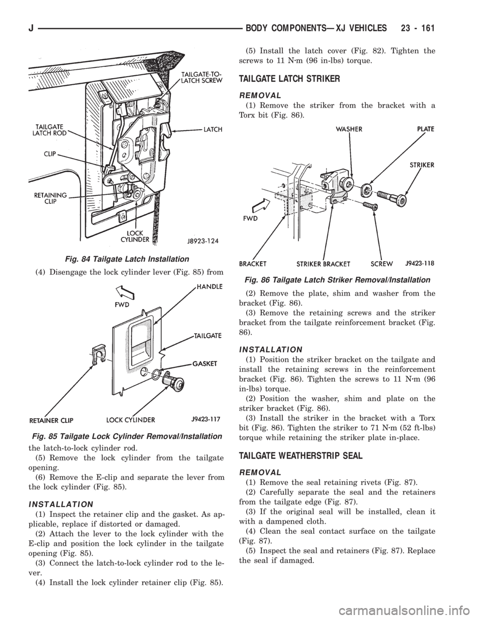
(4) Disengage the lock cylinder lever (Fig. 85) from
the latch-to-lock cylinder rod.
(5) Remove the lock cylinder from the tailgate
opening.
(6) Remove the E-clip and separate the lever from
the lock cylinder (Fig. 85).
INSTALLATION
(1) Inspect the retainer clip and the gasket. As ap-
plicable, replace if distorted or damaged.
(2) Attach the lever to the lock cylinder with the
E-clip and position the lock cylinder in the tailgate
opening (Fig. 85).
(3) Connect the latch-to-lock cylinder rod to the le-
ver.
(4) Install the lock cylinder retainer clip (Fig. 85).(5) Install the latch cover (Fig. 82). Tighten the
screws to 11 Nzm (96 in-lbs) torque.
TAILGATE LATCH STRIKER
REMOVAL
(1) Remove the striker from the bracket with a
Torx bit (Fig. 86).
(2) Remove the plate, shim and washer from the
bracket (Fig. 86).
(3) Remove the retaining screws and the striker
bracket from the tailgate reinforcement bracket (Fig.
86).
INSTALLATION
(1) Position the striker bracket on the tailgate and
install the retaining screws in the reinforcement
bracket (Fig. 86). Tighten the screws to 11 Nzm (96
in-lbs) torque.
(2) Position the washer, shim and plate on the
striker bracket (Fig. 86).
(3) Install the striker in the bracket with a Torx
bit (Fig. 86). Tighten the striker to 71 Nzm (52 ft-lbs)
torque while retaining the striker plate in-place.
TAILGATE WEATHERSTRIP SEAL
REMOVAL
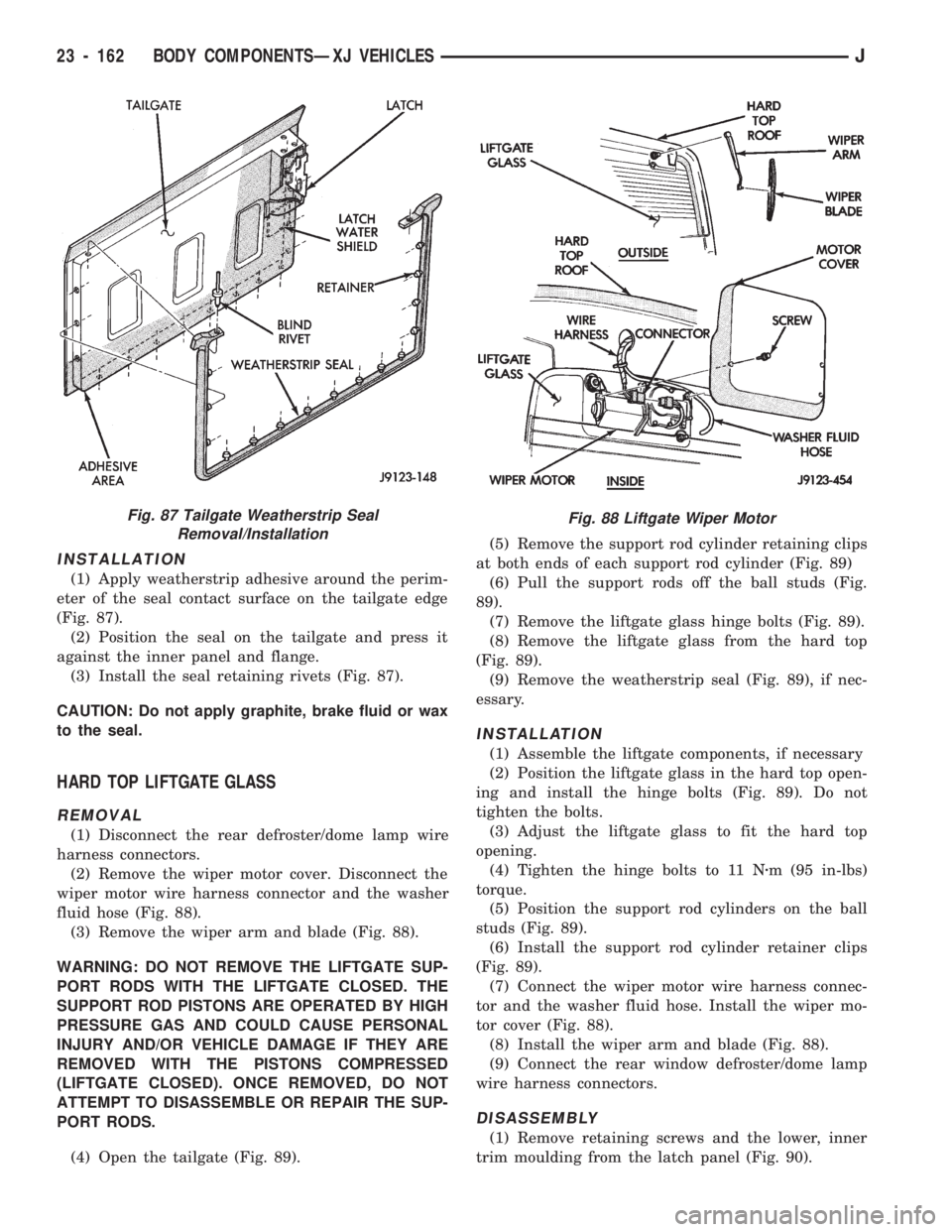
(1) Remove the seal retaining rivets (Fig. 87).
(2) Carefully separate the seal and the retainers
from the tailgate edge (Fig. 87).
(3) If the original seal will be installed, clean it
with a dampened cloth.
(4) Clean the seal contact surface on the tailgate
(Fig. 87).
(5) Inspect the seal and retainers (Fig. 87). Replace
the seal if damaged.
Fig. 84 Tailgate Latch Installation
Fig. 85 Tailgate Lock Cylinder Removal/Installation
Fig. 86 Tailgate Latch Striker Removal/Installation
JBODY COMPONENTSÐXJ VEHICLES 23 - 161
Page 1617 of 1784
INSTALLATION
(1) Apply weatherstrip adhesive around the perim-
eter of the seal contact surface on the tailgate edge
(Fig. 87).
(2) Position the seal on the tailgate and press it
against the inner panel and flange.
(3) Install the seal retaining rivets (Fig. 87).
CAUTION: Do not apply graphite, brake fluid or wax
to the seal.
HARD TOP LIFTGATE GLASS
REMOVAL
(1) Disconnect the rear defroster/dome lamp wire
harness connectors.
(2) Remove the wiper motor cover. Disconnect the
wiper motor wire harness connector and the washer
fluid hose (Fig. 88).
(3) Remove the wiper arm and blade (Fig. 88).
WARNING: DO NOT REMOVE THE LIFTGATE SUP-
PORT RODS WITH THE LIFTGATE CLOSED. THE
SUPPORT ROD PISTONS ARE OPERATED BY HIGH
PRESSURE GAS AND COULD CAUSE PERSONAL
INJURY AND/OR VEHICLE DAMAGE IF THEY ARE
REMOVED WITH THE PISTONS COMPRESSED
(LIFTGATE CLOSED). ONCE REMOVED, DO NOT
ATTEMPT TO DISASSEMBLE OR REPAIR THE SUP-
PORT RODS.
(4) Open the tailgate (Fig. 89).(5) Remove the support rod cylinder retaining clips
at both ends of each support rod cylinder (Fig. 89)
(6) Pull the support rods off the ball studs (Fig.
89).
(7) Remove the liftgate glass hinge bolts (Fig. 89).
(8) Remove the liftgate glass from the hard top
(Fig. 89).
(9) Remove the weatherstrip seal (Fig. 89), if nec-
essary.
INSTALLATION
(1) Assemble the liftgate components, if necessary
(2) Position the liftgate glass in the hard top open-
ing and install the hinge bolts (Fig. 89). Do not
tighten the bolts.
(3) Adjust the liftgate glass to fit the hard top
opening.
(4) Tighten the hinge bolts to 11 Nzm (95 in-lbs)
torque.
(5) Position the support rod cylinders on the ball
studs (Fig. 89).
(6) Install the support rod cylinder retainer clips
(Fig. 89).
(7) Connect the wiper motor wire harness connec-
tor and the washer fluid hose. Install the wiper mo-
tor cover (Fig. 88).
(8) Install the wiper arm and blade (Fig. 88).
(9) Connect the rear window defroster/dome lamp
wire harness connectors.
DISASSEMBLY
(1) Remove retaining screws and the lower, inner
trim moulding from the latch panel (Fig. 90).
Fig. 87 Tailgate Weatherstrip Seal
Removal/InstallationFig. 88 Liftgate Wiper Motor
23 - 162 BODY COMPONENTSÐXJ VEHICLESJ
Page 1618 of 1784
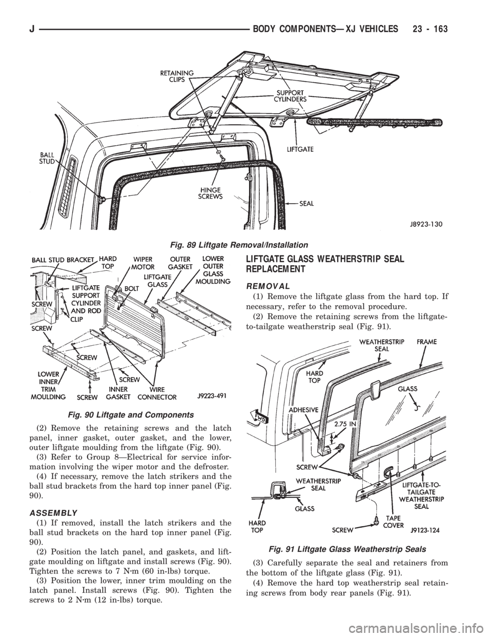
(2) Remove the retaining screws and the latch
panel, inner gasket, outer gasket, and the lower,
outer liftgate moulding from the liftgate (Fig. 90).
(3) Refer to Group 8ÐElectrical for service infor-
mation involving the wiper motor and the defroster.
(4) If necessary, remove the latch strikers and the
ball stud brackets from the hard top inner panel (Fig.
90).
ASSEMBLY
(1) If removed, install the latch strikers and the
ball stud brackets on the hard top inner panel (Fig.
90).
(2) Position the latch panel, and gaskets, and lift-
gate moulding on liftgate and install screws (Fig. 90).
Tighten the screws to 7 Nzm (60 in-lbs) torque.
(3) Position the lower, inner trim moulding on the
latch panel. Install screws (Fig. 90). Tighten the
screws to 2 Nzm (12 in-lbs) torque.
LIFTGATE GLASS WEATHERSTRIP SEAL
REPLACEMENT
REMOVAL
(1) Remove the liftgate glass from the hard top. If
necessary, refer to the removal procedure.
(2) Remove the retaining screws from the liftgate-
to-tailgate weatherstrip seal (Fig. 91).
(3) Carefully separate the seal and retainers from
the bottom of the liftgate glass (Fig. 91).
(4) Remove the hard top weatherstrip seal retain-
ing screws from body rear panels (Fig. 91).
Fig. 91 Liftgate Glass Weatherstrip Seals
Fig. 89 Liftgate Removal/Installation
Fig. 90 Liftgate and Components
JBODY COMPONENTSÐXJ VEHICLES 23 - 163
Page 1627 of 1784
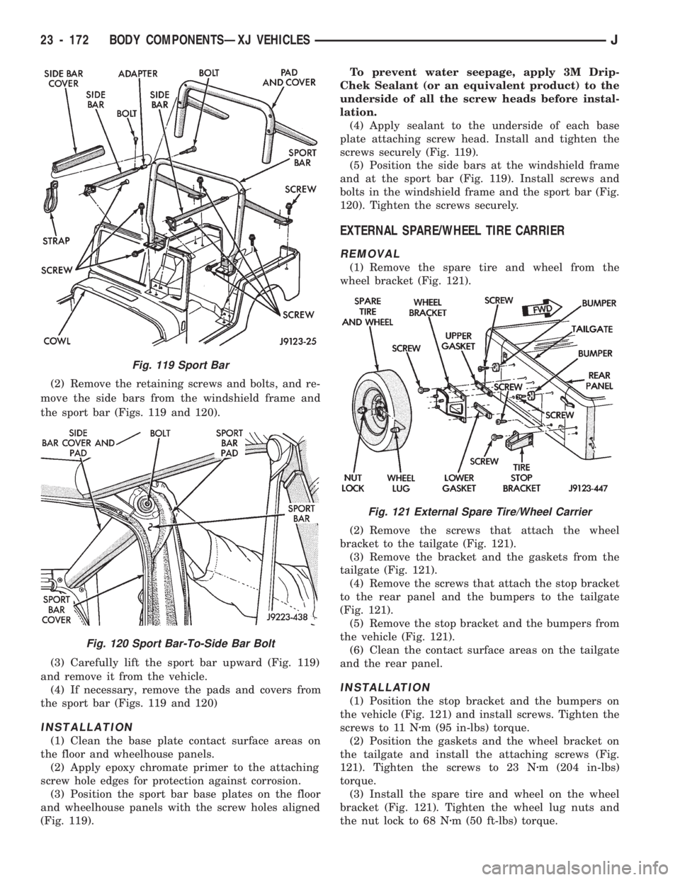
(2) Remove the retaining screws and bolts, and re-
move the side bars from the windshield frame and
the sport bar (Figs. 119 and 120).
(3) Carefully lift the sport bar upward (Fig. 119)
and remove it from the vehicle.
(4) If necessary, remove the pads and covers from
the sport bar (Figs. 119 and 120)
INSTALLATION
(1) Clean the base plate contact surface areas on
the floor and wheelhouse panels.
(2) Apply epoxy chromate primer to the attaching
screw hole edges for protection against corrosion.
(3) Position the sport bar base plates on the floor
and wheelhouse panels with the screw holes aligned
(Fig. 119).To prevent water seepage, apply 3M Drip-
Chek Sealant (or an equivalent product) to the
underside of all the screw heads before instal-
lation.
(4) Apply sealant to the underside of each base
plate attaching screw head. Install and tighten the
screws securely (Fig. 119).
(5) Position the side bars at the windshield frame
and at the sport bar (Fig. 119). Install screws and
bolts in the windshield frame and the sport bar (Fig.
120). Tighten the screws securely.
EXTERNAL SPARE/WHEEL TIRE CARRIER
REMOVAL
(1) Remove the spare tire and wheel from the
wheel bracket (Fig. 121).
(2) Remove the screws that attach the wheel
bracket to the tailgate (Fig. 121).
(3) Remove the bracket and the gaskets from the
tailgate (Fig. 121).
(4) Remove the screws that attach the stop bracket
to the rear panel and the bumpers to the tailgate
(Fig. 121).
(5) Remove the stop bracket and the bumpers from
the vehicle (Fig. 121).
(6) Clean the contact surface areas on the tailgate
and the rear panel.
INSTALLATION
(1) Position the stop bracket and the bumpers on
the vehicle (Fig. 121) and install screws. Tighten the
screws to 11 Nzm (95 in-lbs) torque.
(2) Position the gaskets and the wheel bracket on
the tailgate and install the attaching screws (Fig.
121). Tighten the screws to 23 Nzm (204 in-lbs)
torque.
(3) Install the spare tire and wheel on the wheel
bracket (Fig. 121). Tighten the wheel lug nuts and
the nut lock to 68 Nzm (50 ft-lbs) torque.
Fig. 119 Sport Bar
Fig. 120 Sport Bar-To-Side Bar Bolt
Fig. 121 External Spare Tire/Wheel Carrier
23 - 172 BODY COMPONENTSÐXJ VEHICLESJ