1994 JEEP CHEROKEE torque
[x] Cancel search: torquePage 1595 of 1784
INSTALLATION
(1) Position the cowl screen and grille on the cowl.
(2) Attach the grille and screen to the cowl and the
air intake duct with the screws (Fig. 16).
BATTERY TRAY
REMOVAL
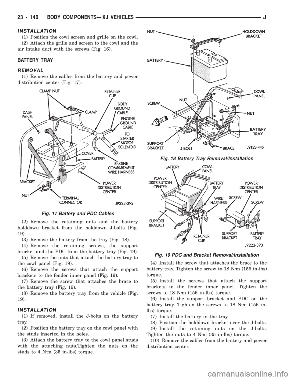
(1) Remove the cables from the battery and power
distribution center (Fig. 17).
(2) Remove the retaining nuts and the battery
holddown bracket from the holddown J-bolts (Fig.
19).
(3) Remove the battery from the tray (Fig. 18).
(4) Remove the retaining screws, the support
bracket and the PDC from the battery tray (Fig. 19).
(5) Remove the nuts that attach the battery tray to
the cowl panel (Fig. 19).
(6) Remove the screws that attach the support
brackets to the fender inner panel (Fig. 19).
(7) Remove the screw that attaches the brace to
the battery tray (Fig. 19).
(8) Remove the battery tray from the vehicle (Fig.
19).
INSTALLATION
(1) If removed, install the J-bolts on the battery
tray.
(2) Position the battery tray on the cowl panel with
the studs inserted in the holes.
(3) Attach the battery tray to the cowl panel studs
with the attaching nuts.Tighten the nuts on the
studs to 4 Nzm (35 in-lbs) torque.(4) Install the screw that attaches the brace to the
battery tray. Tighten the screw to 18 Nzm (156 in-lbs)
torque.
(5) Install the screws that attach the support
brackets to the fender inner panel. Tighten the
screws to 18 Nzm (156 in-lbs) torque.
(6) Install the support bracket and PDC on the
battery tray. Tighten the screws to 18 Nzm (156 in-
lbs) torque.
(7) Install the battery in the tray.
(8) Position the holddown bracket over the J-bolts.
(9) Install the retaining nuts on the J-bolts.
Tighten the nuts to 4 Nzm (35 in-lbs) torque.
(10) Remove the cables from the battery and power
distribution center.
Fig. 17 Battery and PDC Cables
Fig. 18 Battery Tray Removal/Installation
Fig. 19 PDC and Bracket Removal/Installation
23 - 140 BODY COMPONENTSÐXJ VEHICLESJ
Page 1599 of 1784
INSTALLATION
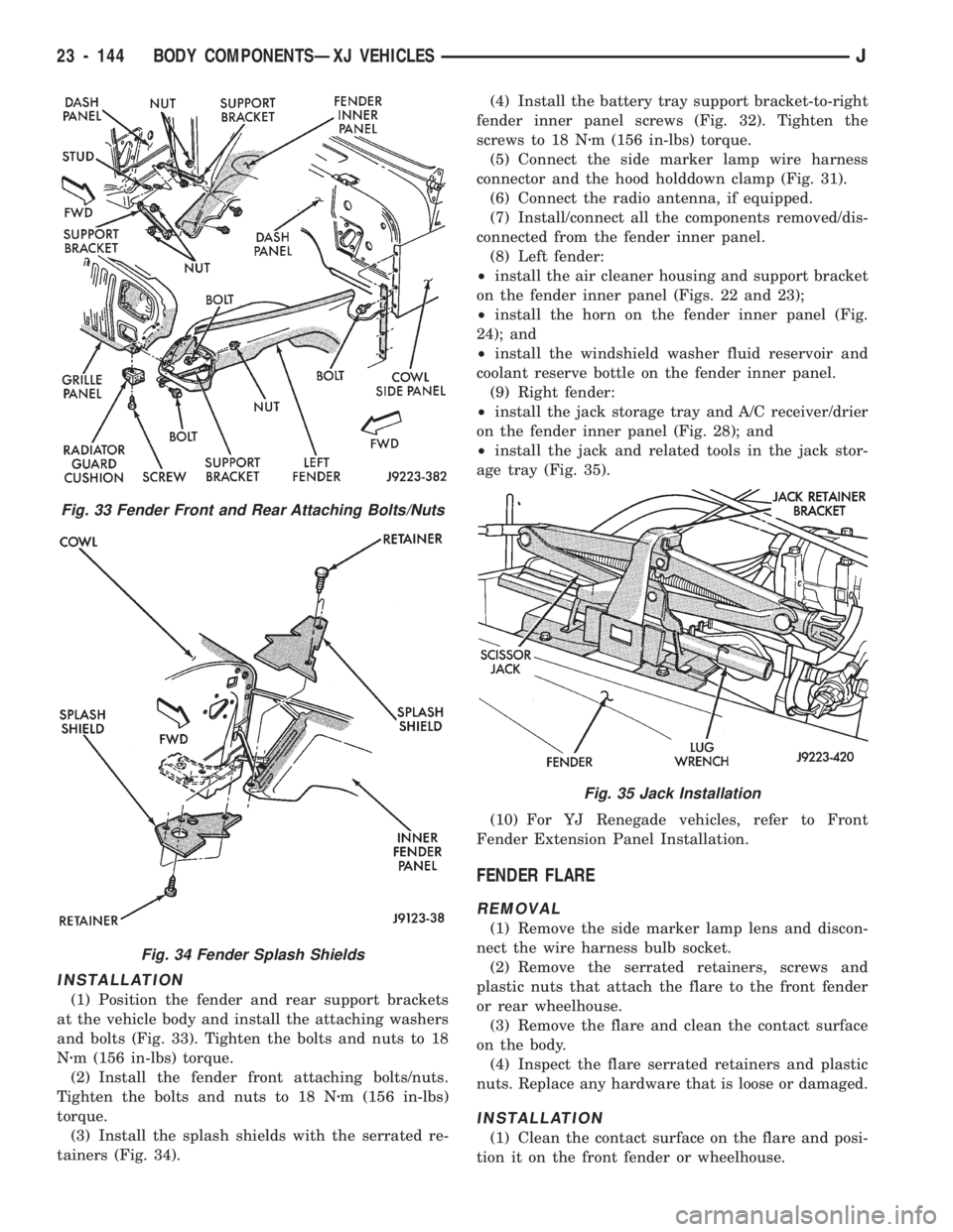
(1) Position the fender and rear support brackets
at the vehicle body and install the attaching washers
and bolts (Fig. 33). Tighten the bolts and nuts to 18
Nzm (156 in-lbs) torque.
(2) Install the fender front attaching bolts/nuts.
Tighten the bolts and nuts to 18 Nzm (156 in-lbs)
torque.
(3) Install the splash shields with the serrated re-
tainers (Fig. 34).(4) Install the battery tray support bracket-to-right
fender inner panel screws (Fig. 32). Tighten the
screws to 18 Nzm (156 in-lbs) torque.
(5) Connect the side marker lamp wire harness
connector and the hood holddown clamp (Fig. 31).
(6) Connect the radio antenna, if equipped.
(7) Install/connect all the components removed/dis-
connected from the fender inner panel.
(8) Left fender:
²install the air cleaner housing and support bracket
on the fender inner panel (Figs. 22 and 23);
²install the horn on the fender inner panel (Fig.
24); and
²install the windshield washer fluid reservoir and
coolant reserve bottle on the fender inner panel.
(9) Right fender:
²install the jack storage tray and A/C receiver/drier
on the fender inner panel (Fig. 28); and
²install the jack and related tools in the jack stor-
age tray (Fig. 35).
(10) For YJ Renegade vehicles, refer to Front
Fender Extension Panel Installation.
FENDER FLARE
REMOVAL
(1) Remove the side marker lamp lens and discon-
nect the wire harness bulb socket.
(2) Remove the serrated retainers, screws and
plastic nuts that attach the flare to the front fender
or rear wheelhouse.
(3) Remove the flare and clean the contact surface
on the body.
(4) Inspect the flare serrated retainers and plastic
nuts. Replace any hardware that is loose or damaged.
INSTALLATION
(1) Clean the contact surface on the flare and posi-
tion it on the front fender or wheelhouse.
Fig. 33 Fender Front and Rear Attaching Bolts/Nuts
Fig. 34 Fender Splash Shields
Fig. 35 Jack Installation
23 - 144 BODY COMPONENTSÐXJ VEHICLESJ
Page 1600 of 1784
(2) Install the flare serrated retainers, screws and
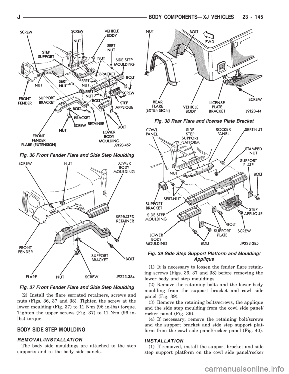
nuts (Figs. 36, 37 and 38). Tighten the screw at the
lower moulding (Fig. 37) to 11 Nzm (96 in-lbs) torque.
Tighten the upper screws (Fig. 37) to 11 Nzm (96 in-
lbs) torque.
BODY SIDE STEP MOULDING
REMOVAL/INSTALLATION
The body side mouldings are attached to the step
supports and to the body side panels.(1) It is necessary to loosen the fender flare retain-
ing screws (Figs. 36, 37 and 38) before removing the
lower body and step mouldings.
(2) Remove the retaining bolts and the lower body
moulding from the support bracket and cowl side
panel (Fig. 39).
(3) Remove the retaining bolts/screws, the applique
and the side step moulding from the cowl side panel/
rocker panel (Fig. 39).
(4) If necessary, remove the retaining bolt/screws
and the support bracket and side step support plat-
form from the cowl side panel/rocker panel (Fig. 40).
INSTALLATION
(1) If removed, install the support bracket and side
step support platform on the cowl side panel/rocker
Fig. 38 Rear Flare and license Plate Bracket
Fig. 39 Side Step Support Platform and Moulding/
Applique
Fig. 36 Front Fender Flare and Side Step Moulding
Fig. 37 Front Fender Flare and Side Step Moulding
JBODY COMPONENTSÐXJ VEHICLES 23 - 145
Page 1601 of 1784
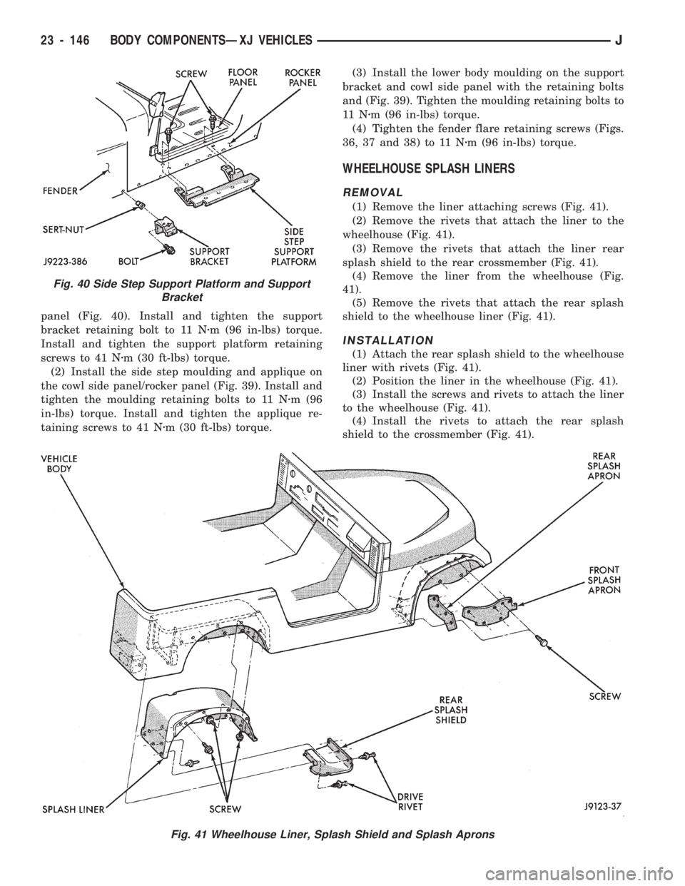
panel (Fig. 40). Install and tighten the support
bracket retaining bolt to 11 Nzm (96 in-lbs) torque.
Install and tighten the support platform retaining
screws to 41 Nzm (30 ft-lbs) torque.
(2) Install the side step moulding and applique on
the cowl side panel/rocker panel (Fig. 39). Install and
tighten the moulding retaining bolts to 11 Nzm (96
in-lbs) torque. Install and tighten the applique re-
taining screws to 41 Nzm (30 ft-lbs) torque.(3) Install the lower body moulding on the support
bracket and cowl side panel with the retaining bolts
and (Fig. 39). Tighten the moulding retaining bolts to
11 Nzm (96 in-lbs) torque.
(4) Tighten the fender flare retaining screws (Figs.
36, 37 and 38) to 11 Nzm (96 in-lbs) torque.
WHEELHOUSE SPLASH LINERS
REMOVAL
(1) Remove the liner attaching screws (Fig. 41).
(2) Remove the rivets that attach the liner to the
wheelhouse (Fig. 41).
(3) Remove the rivets that attach the liner rear
splash shield to the rear crossmember (Fig. 41).
(4) Remove the liner from the wheelhouse (Fig.
41).
(5) Remove the rivets that attach the rear splash
shield to the wheelhouse liner (Fig. 41).
INSTALLATION
(1) Attach the rear splash shield to the wheelhouse
liner with rivets (Fig. 41).
(2) Position the liner in the wheelhouse (Fig. 41).
(3) Install the screws and rivets to attach the liner
to the wheelhouse (Fig. 41).
(4) Install the rivets to attach the rear splash
shield to the crossmember (Fig. 41).
Fig. 41 Wheelhouse Liner, Splash Shield and Splash Aprons
Fig. 40 Side Step Support Platform and Support
Bracket
23 - 146 BODY COMPONENTSÐXJ VEHICLESJ
Page 1604 of 1784
(5) Remove the retaining screws and the fascia
step pad support bracket from the frame crossmem-
ber (Fig. 47).
(6) Remove the retaining bolts from the skid plate.
Remove the skid plate from the brackets.
(7) Remove the retaining screws from the skid
plate brackets. Remove the brackets from the frame
rails.
(8) Remove the retaining bolts and the fascia sup-
port from the cover plate.
INSTALLATION
(1) Position the fascia support on the cover plate
and install the retaining bolts (Fig. 47). Tighten the
bolts to 5 Nzm (44 in-lbs) torque.
(2) Position the skid plate brackets at the frame
rails and install the retaining screws. Tighten the
screws to 25 Nzm (18 ft-lbs) torque.
(3) Position the skid plate at the brackets and in-
stall the retaining bolts. Tighten the bolts to 25 Nzm
(18 ft-lbs) torque.
(4) Position the fascia step pad support bracket at
the frame crossmember and install the retaining
screws. Tighten the screws to 25 Nzm (18 ft-lbs)
torque.
(5) Position the fascia spacer at the frame cross-
member and install the retaining bolts. Tighten the
nuts to 6 Nzm (53 in-lbs) torque.
(6) Position the fascia at the frame crossmember
and install the retaining bolts and push pins.
Tighten the bolts to 10 Nzm (7 ft-lbs) torque.
(7) Install the step pad on the fascia.
(8) If applicable, remove the support and lower the
vehicle.
FRONT FENDER EXTENSION PANELÐYJ RENEGADE
VEHICLES
REMOVAL
(1) For convenience, lift the vehicle to a comfort-
able height on a hoist. Support the vehicle.
(2) Remove the radio antenna mast from the
fender extension panel.
(3) Remove the hood bumper from the extension
panel.
(4) Remove the fog lamp from the extension panel.
If necessary, refer to the removal procedure.
(5) Detach the hood latch from the hood.
(6) Disconnect the side marker lamp wire harness
bulb socket.
(7) Remove the push pins that attach the fender
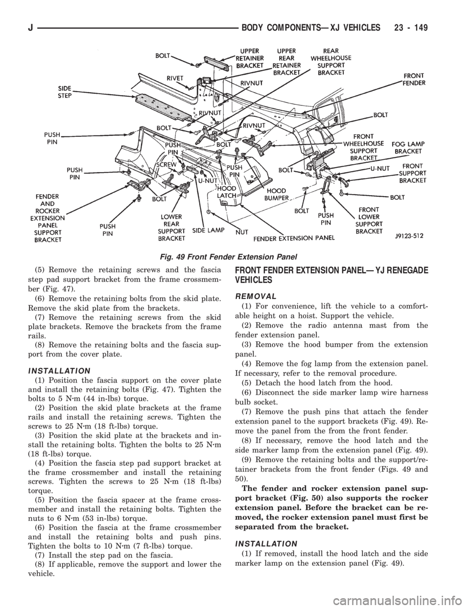
extension panel to the support brackets (Fig. 49). Re-
move the panel from the from the front fender.
(8) If necessary, remove the hood latch and the
side marker lamp from the extension panel (Fig. 49).
(9) Remove the retaining bolts and the support/re-
tainer brackets from the front fender (Figs. 49 and
50).
The fender and rocker extension panel sup-
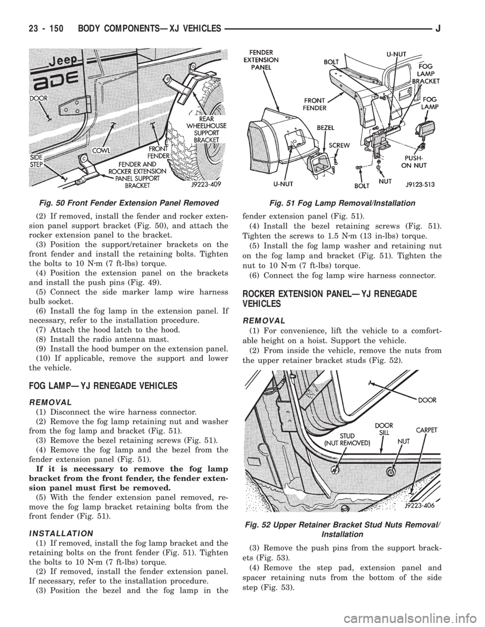
port bracket (Fig. 50) also supports the rocker
extension panel. Before the bracket can be re-
moved, the rocker extension panel must first be
separated from the bracket.
INSTALLATION
(1) If removed, install the hood latch and the side
marker lamp on the extension panel (Fig. 49).
Fig. 49 Front Fender Extension Panel
JBODY COMPONENTSÐXJ VEHICLES 23 - 149
Page 1605 of 1784
(2) If removed, install the fender and rocker exten-
sion panel support bracket (Fig. 50), and attach the
rocker extension panel to the bracket.
(3) Position the support/retainer brackets on the
front fender and install the retaining bolts. Tighten
the bolts to 10 Nzm (7 ft-lbs) torque.
(4) Position the extension panel on the brackets
and install the push pins (Fig. 49).
(5) Connect the side marker lamp wire harness
bulb socket.
(6) Install the fog lamp in the extension panel. If
necessary, refer to the installation procedure.
(7) Attach the hood latch to the hood.
(8) Install the radio antenna mast.
(9) Install the hood bumper on the extension panel.
(10) If applicable, remove the support and lower
the vehicle.
FOG LAMPÐYJ RENEGADE VEHICLES
REMOVAL
(1) Disconnect the wire harness connector.
(2) Remove the fog lamp retaining nut and washer
from the fog lamp and bracket (Fig. 51).
(3) Remove the bezel retaining screws (Fig. 51).
(4) Remove the fog lamp and the bezel from the
fender extension panel (Fig. 51).
If it is necessary to remove the fog lamp
bracket from the front fender, the fender exten-
sion panel must first be removed.
(5) With the fender extension panel removed, re-
move the fog lamp bracket retaining bolts from the
front fender (Fig. 51).
INSTALLATION
(1) If removed, install the fog lamp bracket and the
retaining bolts on the front fender (Fig. 51). Tighten
the bolts to 10 Nzm (7 ft-lbs) torque.
(2) If removed, install the fender extension panel.
If necessary, refer to the installation procedure.
(3) Position the bezel and the fog lamp in thefender extension panel (Fig. 51).
(4) Install the bezel retaining screws (Fig. 51).
Tighten the screws to 1.5 Nzm (13 in-lbs) torque.
(5) Install the fog lamp washer and retaining nut
on the fog lamp and bracket (Fig. 51). Tighten the
nut to 10 Nzm (7 ft-lbs) torque.
(6) Connect the fog lamp wire harness connector.
ROCKER EXTENSION PANELÐYJ RENEGADE
VEHICLES
REMOVAL
(1) For convenience, lift the vehicle to a comfort-
able height on a hoist. Support the vehicle.
(2) From inside the vehicle, remove the nuts from
the upper retainer bracket studs (Fig. 52).
(3) Remove the push pins from the support brack-
ets (Fig. 53).
(4) Remove the step pad, extension panel and
spacer retaining nuts from the bottom of the side
step (Fig. 53).
Fig. 50 Front Fender Extension Panel RemovedFig. 51 Fog Lamp Removal/Installation
Fig. 52 Upper Retainer Bracket Stud Nuts Removal/
Installation
23 - 150 BODY COMPONENTSÐXJ VEHICLESJ
Page 1606 of 1784
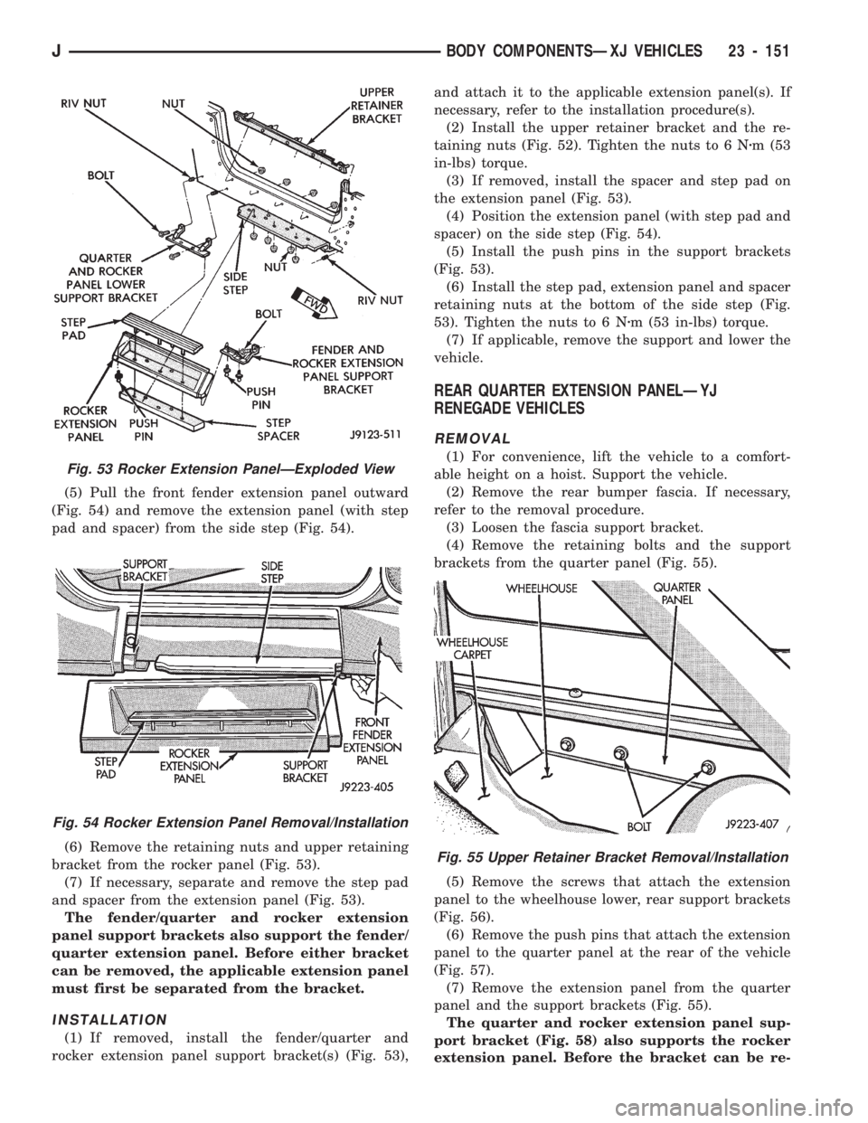
(5) Pull the front fender extension panel outward
(Fig. 54) and remove the extension panel (with step
pad and spacer) from the side step (Fig. 54).
(6) Remove the retaining nuts and upper retaining
bracket from the rocker panel (Fig. 53).
(7) If necessary, separate and remove the step pad
and spacer from the extension panel (Fig. 53).
The fender/quarter and rocker extension
panel support brackets also support the fender/
quarter extension panel. Before either bracket
can be removed, the applicable extension panel
must first be separated from the bracket.
INSTALLATION
(1) If removed, install the fender/quarter and
rocker extension panel support bracket(s) (Fig. 53),and attach it to the applicable extension panel(s). If
necessary, refer to the installation procedure(s).
(2) Install the upper retainer bracket and the re-
taining nuts (Fig. 52). Tighten the nuts to 6 Nzm (53
in-lbs) torque.
(3) If removed, install the spacer and step pad on
the extension panel (Fig. 53).
(4) Position the extension panel (with step pad and
spacer) on the side step (Fig. 54).
(5) Install the push pins in the support brackets
(Fig. 53).
(6) Install the step pad, extension panel and spacer
retaining nuts at the bottom of the side step (Fig.
53). Tighten the nuts to 6 Nzm (53 in-lbs) torque.
(7) If applicable, remove the support and lower the
vehicle.
REAR QUARTER EXTENSION PANELÐYJ
RENEGADE VEHICLES
REMOVAL
(1) For convenience, lift the vehicle to a comfort-
able height on a hoist. Support the vehicle.
(2) Remove the rear bumper fascia. If necessary,
refer to the removal procedure.
(3) Loosen the fascia support bracket.
(4) Remove the retaining bolts and the support
brackets from the quarter panel (Fig. 55).
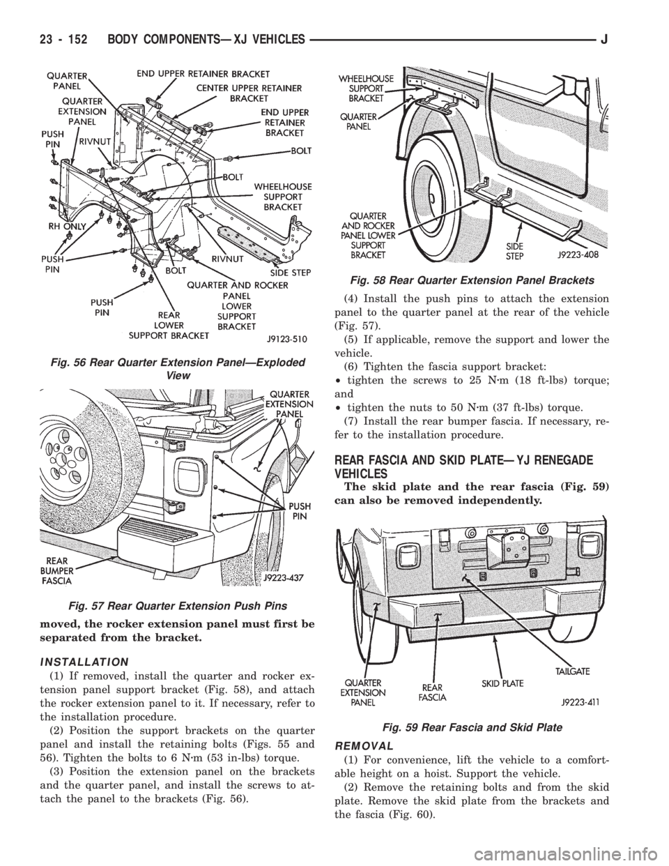
(5) Remove the screws that attach the extension
panel to the wheelhouse lower, rear support brackets
(Fig. 56).
(6) Remove the push pins that attach the extension
panel to the quarter panel at the rear of the vehicle
(Fig. 57).
(7) Remove the extension panel from the quarter
panel and the support brackets (Fig. 55).
The quarter and rocker extension panel sup-
port bracket (Fig. 58) also supports the rocker
extension panel. Before the bracket can be re-
Fig. 55 Upper Retainer Bracket Removal/Installation
Fig. 53 Rocker Extension PanelÐExploded View
Fig. 54 Rocker Extension Panel Removal/Installation
JBODY COMPONENTSÐXJ VEHICLES 23 - 151
Page 1607 of 1784
moved, the rocker extension panel must first be
separated from the bracket.
INSTALLATION
(1) If removed, install the quarter and rocker ex-
tension panel support bracket (Fig. 58), and attach
the rocker extension panel to it. If necessary, refer to
the installation procedure.
(2) Position the support brackets on the quarter
panel and install the retaining bolts (Figs. 55 and
56). Tighten the bolts to 6 Nzm (53 in-lbs) torque.
(3) Position the extension panel on the brackets
and the quarter panel, and install the screws to at-
tach the panel to the brackets (Fig. 56).(4) Install the push pins to attach the extension
panel to the quarter panel at the rear of the vehicle
(Fig. 57).
(5) If applicable, remove the support and lower the
vehicle.
(6) Tighten the fascia support bracket:
²tighten the screws to 25 Nzm (18 ft-lbs) torque;
and
²tighten the nuts to 50 Nzm (37 ft-lbs) torque.
(7) Install the rear bumper fascia. If necessary, re-
fer to the installation procedure.
REAR FASCIA AND SKID PLATEÐYJ RENEGADE
VEHICLES
The skid plate and the rear fascia (Fig. 59)
can also be removed independently.
REMOVAL
(1) For convenience, lift the vehicle to a comfort-
able height on a hoist. Support the vehicle.
(2) Remove the retaining bolts and from the skid
plate. Remove the skid plate from the brackets and
the fascia (Fig. 60).
Fig. 56 Rear Quarter Extension PanelÐExploded
View
Fig. 57 Rear Quarter Extension Push Pins
Fig. 58 Rear Quarter Extension Panel Brackets
Fig. 59 Rear Fascia and Skid Plate
23 - 152 BODY COMPONENTSÐXJ VEHICLESJ