1993 FORD MONDEO radiator cap
[x] Cancel search: radiator capPage 90 of 279
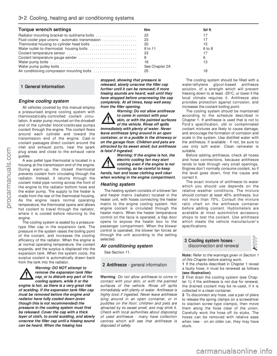
Torque wrench settingsNm lbf ft
Radiator mounting bracket-to-subframe bolts . . . . . . . . . . . . . . . . . . . . 23 17
Fluid cooler pipe unions - automatic transmission . . . . . . . . . . . . . . . . . 23 17
Thermostat housing-to-cylinder head bolts . . . . . . . . . . . . . . . . . . . . . . 20 15
Water outlet-to-thermostat housing bolts . . . . . . . . . . . . . . . . . . . . . . . 8 to 11 6 to 8
Coolant temperature sensor . . . . . . . . . . . . . . . . . . . . . . . . . . . . . . . . . . 23 17
Coolant temperature gauge sender . . . . . . . . . . . . . . . . . . . . . . . . . . . . 8 6
Water pump bolts . . . . . . . . . . . . . . . . . . . . . . . . . . . . . . . . . . . . . . . . . . 18 13
Water pump pulley bolts . . . . . . . . . . . . . . . . . . . . . . . . . . . . . . . . . . . . . See Chapter 2A
Air conditioning compressor mounting bolts . . . . . . . . . . . . . . . . . . . . . 25 18
3•2 Cooling, heating and air conditioning systems
Engine cooling system
All vehicles covered by this manual employ
a pressurised engine cooling system with
thermostatically-controlled coolant circu-
lation. A water pump mounted on the drivebelt
end of the cylinder block/crankcase pumps
coolant through the engine. The coolant flows
around each cylinder and toward the
transmission end of the engine. Cast-in
coolant passages direct coolant around the
inlet and exhaust ports, near the spark
plug areas and close to the exhaust valve
guides.
A wax pellet type thermostat is located in a
housing at the transmission end of the engine.
During warm-up, the closed thermostat
prevents coolant from circulating through the
radiator. Instead, it returns through the
coolant metal pipe running across the front of
the engine to the radiator bottom hose and
the water pump. The supply to the heater is
made from the rear of the thermostat housing.
As the engine nears normal operating
temperature, the thermostat opens and allows
hot coolant to travel through the radiator,
where it is cooled before returning to the
engine.
The cooling system is sealed by a pressure-
type filler cap in the expansion tank. The
pressure in the system raises the boiling point
of the coolant, and increases the cooling
efficiency of the radiator. When the engine is
at normal operating temperature, the coolant
expands, and the surplus is displaced into the
expansion tank. When the system cools, the
surplus coolant is automatically drawn back
from the tank into the radiator.
Warning: DO NOT attempt to
remove the expansion tank filler
cap, or to disturb any part of the
cooling system, while it or the
engine is hot, as there is a very great risk
of scalding. If the expansion tank filler cap
must be removed before the engine and
radiator have fully cooled down (even
though this is not recommended) the
pressure in the cooling system must first
be released. Cover the cap with a thick
layer of cloth, to avoid scalding, and slowly
unscrew the filler cap until a hissing sound
can be heard. When the hissing hasstopped, showing that pressure is
released, slowly unscrew the filler cap
further until it can be removed; if more
hissing sounds are heard, wait until they
have stopped before unscrewing the cap
completely. At all times, keep well away
from the filler opening.
Warning: Do not allow antifreeze
to come in contact with your
skin, or with the painted surfaces
of the vehicle. Rinse off spills
immediately with plenty of water. Never
leave antifreeze lying around in an open
container, or in a puddle in the driveway or
on the garage floor. Children and pets are
attracted by its sweet smell, but antifreeze
is fatal if ingested.
Warning: If the engine is hot, the
electric cooling fan may start
rotating even if the engine is not
running, so be careful to keep
hands, hair and loose clothing well clear
when working in the engine compartment.
Heating system
The heating system consists of a blower fan
and heater matrix (radiator) located in the
heater unit, with hoses connecting the heater
matrix to the engine cooling system. Hot
engine coolant is circulated through the
heater matrix. When the heater temperature
control on the facia is operated, a flap door
opens to expose the heater box to the
passenger compartment. When the blower
control is operated, the blower fan forces air
through the unit according to the setting
selected.
Air conditioning system
See Section 11.
Warning: Do not allow antifreeze to come in
contact with your skin, or with the painted
surfaces of the vehicle. Rinse off spills
immediately with plenty of water. Antifreeze is
highly toxic if ingested. Never leave antifreeze
lying around in an open container, or in
puddles on the floor; children and pets are
attracted by its sweet smell, and may drink it.
Check with local authorities about disposing
of used antifreeze - many have collection
centres which will see that antifreeze is
disposed of safely.The cooling system should be filled with a
water/ethylene glycol-based antifreeze
solution, of a strength which will prevent
freezing down to at least -25°C, or lower if the
local climate requires it. Antifreeze also
provides protection against corrosion, and
increases the coolant boiling point.
The cooling system should be maintained
according to the schedule described in
Chapter 1. If antifreeze is used that is not to
Ford’s specification, old or contaminated
coolant mixtures are likely to cause damage,
and encourage the formation of corrosion and
scale in the system. Use distilled water with
the antifreeze, if available - if not, be sure to
use only soft water. Clean rainwater is
suitable.
Before adding antifreeze, check all hoses
and hose connections, because antifreeze
tends to leak through very small openings.
Engines don’t normally consume coolant, so if
the level goes down, find the cause and
correct it.
The exact mixture of antifreeze-to-water
which you should use depends on the
relative weather conditions. The mixture
should contain at least 40% antifreeze, but
not more than 70%. Consult the mixture
ratio chart on the antifreeze container
before adding coolant. Hydrometers are
available at most automotive accessory
shops to test the coolant. Use antifreeze
which meets the vehicle manufacturer’s
specifications.
Note:Refer to the warnings given in Section 1
of this Chapter before starting work.
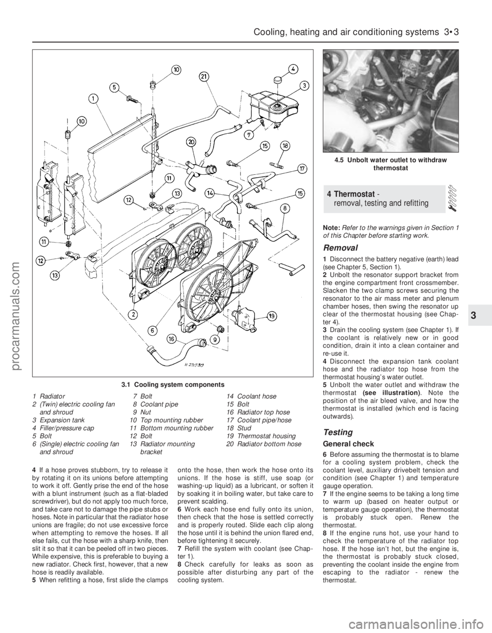
1If the checks described in Chapter 1 reveal
a faulty hose, it must be renewed as follows
(see illustration).
2First drain the cooling system (see Chap-
ter 1); if the antifreeze is not due for renewal,
the drained coolant may be re-used, if it is
collected in a clean container.
3To disconnect any hose, use a pair of pliers
to release the spring clamps (or a screwdriver
to slacken screw-type clamps), then move
them along the hose clear of the union.
Carefully work the hose off its stubs. The
hoses can be removed with relative ease
when new - on an older car, they may have
stuck.
3 Cooling system hoses -
disconnection and renewal
2 Antifreeze - general information
1 General information
procarmanuals.com
Page 91 of 279
4If a hose proves stubborn, try to release it
by rotating it on its unions before attempting
to work it off. Gently prise the end of the hose
with a blunt instrument (such as a flat-bladed
screwdriver), but do not apply too much force,
and take care not to damage the pipe stubs or
hoses. Note in particular that the radiator hose
unions are fragile; do not use excessive force
when attempting to remove the hoses. If all
else fails, cut the hose with a sharp knife, then
slit it so that it can be peeled off in two pieces.
While expensive, this is preferable to buying a
new radiator. Check first, however, that a new
hose is readily available.
5When refitting a hose, first slide the clampsonto the hose, then work the hose onto its
unions. If the hose is stiff, use soap (or
washing-up liquid) as a lubricant, or soften it
by soaking it in boiling water, but take care to
prevent scalding.
6Work each hose end fully onto its union,
then check that the hose is settled correctly
and is properly routed. Slide each clip along
the hose until it is behind the union flared end,
before tightening it securely.
7Refill the system with coolant (see Chap-
ter 1).
8Check carefully for leaks as soon as
possible after disturbing any part of the
cooling system.Note:Refer to the warnings given in Section 1
of this Chapter before starting work.
Removal
1Disconnect the battery negative (earth) lead
(see Chapter 5, Section 1).
2Unbolt the resonator support bracket from
the engine compartment front crossmember.
Slacken the two clamp screws securing the
resonator to the air mass meter and plenum
chamber hoses, then swing the resonator up
clear of the thermostat housing (see Chap-
ter 4).
3Drain the cooling system (see Chapter 1). If
the coolant is relatively new or in good
condition, drain it into a clean container and
re-use it.
4Disconnect the expansion tank coolant
hose and the radiator top hose from the
thermostat housing’s water outlet.
5Unbolt the water outlet and withdraw the
thermostat (see illustration). Note the
position of the air bleed valve, and how the
thermostat is installed (which end is facing
outwards).
Testing
General check
6Before assuming the thermostat is to blame
for a cooling system problem, check the
coolant level, auxiliary drivebelt tension and
condition (see Chapter 1) and temperature
gauge operation.
7If the engine seems to be taking a long time
to warm up (based on heater output or
temperature gauge operation), the thermostat
is probably stuck open. Renew the
thermostat.
8If the engine runs hot, use your hand to
check the temperature of the radiator top
hose. If the hose isn’t hot, but the engine is,
the thermostat is probably stuck closed,
preventing the coolant inside the engine from
escaping to the radiator - renew the
thermostat.
4 Thermostat -
removal, testing and refitting
Cooling, heating and air conditioning systems 3•3
3
4.5 Unbolt water outlet to withdraw
thermostat
3.1 Cooling system components
1 Radiator
2 (Twin) electric cooling fan
and shroud
3 Expansion tank
4 Filler/pressure cap
5 Bolt
6 (Single) electric cooling fan
and shroud7 Bolt
8 Coolant pipe
9 Nut
10 Top mounting rubber
11 Bottom mounting rubber
12 Bolt
13 Radiator mounting
bracket14 Coolant hose
15 Bolt
16 Radiator top hose
17 Coolant pipe/hose
18 Stud
19 Thermostat housing
20 Radiator bottom hose
procarmanuals.com
Page 93 of 279
sender’s electrical connector, and use a
jumper wire to connect the white/red wire to a
clean earth point (bare metal) on the engine.
Switch on the ignition without starting the
engine. If the gauge now indicates Hot, renew
the sender.
5If the gauge still does not work, the circuit
may be open, or the gauge may be faulty. See
Chapter 12 for additional information.
Removal
6Unbolt the resonator support bracket from
the engine compartment front crossmember.
Slacken the two clamp screws securing the
resonator to the air mass meter and plenum
chamber hoses, then swing the resonator up
clear of the thermostat housing (see Chap-
ter 4).
7Drain the cooling system (see Chapter 1).
8Disconnect the expansion tank coolant
hose and the radiator top hose from the
thermostat housing’s water outlet, then
disconnect the metal coolant pipe/hose from
the thermostat.
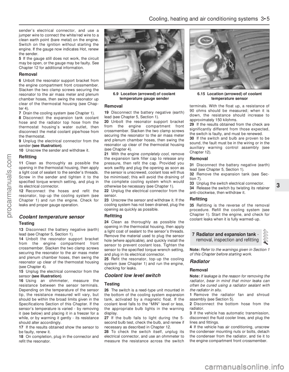
9Unplug the electrical connector from the
sender (see illustration).
10Unscrew the sender and withdraw it.
Refitting
11Clean as thoroughly as possible the
opening in the thermostat housing, then apply
a light coat of sealant to the sender’s threads.
Screw in the sender and tighten it to the
specified torque wrench setting, and plug in
its electrical connector.
12Reconnect the hoses and refit the
resonator, top-up the cooling system (see
Chapter 1) and run the engine. Check for
leaks and proper gauge operation.
Coolant temperature sensor
Testing
13Disconnect the battery negative (earth)
lead (see Chapter 5, Section 1).
14Unbolt the resonator support bracket
from the engine compartment front
crossmember. Slacken the two clamp screws
securing the resonator to the air mass meter
and plenum chamber hoses, then swing the
resonator up clear of the thermostat housing
(see Chapter 4).
15Unplug the electrical connector from the
sensor (see illustration).
16Using an ohmmeter, measure the
resistance between the sensor terminals.
Depending on the temperature of the sensor
tip, the resistance measured will vary, but
should be within the broad limits given in the
Specifications Section of this Chapter. If the
sensor’s temperature is varied - by removing
it (see below) and placing it in a freezer for a
while, or by warming it gently - its resistance
should alter accordingly.
17If the results obtained show the sensor to
be faulty, renew it.
18On completion, plug in the connector and
refit the resonator.
Removal
19Disconnect the battery negative (earth)
lead (see Chapter 5, Section 1).
20Unbolt the resonator support bracket
from the engine compartment front
crossmember. Slacken the two clamp screws
securing the resonator to the air mass meter
and plenum chamber hoses, then swing the
resonator up clear of the thermostat housing
(see Chapter 4).
21With the engine completely cool, remove
the expansion tank filler cap to release any
pressure, then refit the cap. Provided you
work swiftly and plug the opening as soon as
the sensor is unscrewed, coolant loss will thus
be minimised; this will avoid the draining of
the complete cooling system which would
otherwise be necessary (see Chapter 1).
22Unplug the electrical connector from the
sensor.
23Unscrew the sensor and withdraw it. If the
cooling system has not been drained, plug the
opening as quickly as possible.
Refitting
24Clean as thoroughly as possible the
opening in the thermostat housing, then apply
a light coat of sealant to the sensor’s threads.
Remove the material used to plug the sensor
hole (where applicable), and quickly install the
sensor to prevent coolant loss. Tighten the
sensor to the specified torque wrench setting,
and plug in its electrical connector.
25Refit the resonator, top-up the cooling
system (see Chapter 1) and run the engine,
checking for leaks.
Coolant low level switch
Testing
26The switch is a reed-type unit mounted in
the bottom of the cooling system expansion
tank, activated by a magnetic float. If the
coolant level falls to the “MIN” level or less,
the appropriate bulb lights in the warning
display.
27If the bulb fails to light during the 5-
second bulb test, check the bulb, and renew if
necessary as described in Chapter 12.
28To check the switch itself, unplug its
electrical connector, and use an ohmmeter to
measure the resistance across the switchterminals. With the float up, a resistance of
90 ohms should be measured; when it is
down, the resistance should increase to
approximately 150 kilohms.
29If the results obtained from the check are
significantly different from those expected,
the switch is faulty, and must be renewed.
30If the switch and bulb are proven to be
sound, the fault must be in the wiring or in the
auxiliary warning control assembly (see
Chapter 12).
Removal
31Disconnect the battery negative (earth)
lead (see Chapter 5, Section 1).
32Remove the expansion tank (see Sec-
tion 7).
33Unplug the switch electrical connector.
34Release the switch by twisting its retainer
anti-clockwise, then withdraw it.
Refitting
35Refitting is the reverse of the removal
procedure. Refill the cooling system (see
Chapter 1). Start the engine, and check for
coolant leaks when it is fully warmed-up.
Note:Refer to the warnings given in Section 1
of this Chapter before starting work.
Radiator
Removal
Note:If leakage is the reason for removing the
radiator, bear in mind that minor leaks can
often be cured using a radiator sealant with
the radiator in situ.
1Remove the radiator fan and shroud
assembly (see Section 5).
2Disconnect the bottom hose from the
radiator.
3If the vehicle has automatic transmission,
disconnect the fluid cooler lines, and plug the
lines and fittings.
4If the vehicle has air conditioning, unscrew
the condenser mounting nuts or bolts, detach
the condenser from the radiator, and tie it to
the engine compartment front crossmember.
7 Radiator and expansion tank -
removal, inspection and refitting
Cooling, heating and air conditioning systems 3•5
3
6.9 Location (arrowed) of coolant
temperature gauge sender6.15 Location (arrowed) of coolant
temperature sensor
procarmanuals.com
Page 94 of 279
Warning: Do not disconnect any
of the refrigerant hoses.
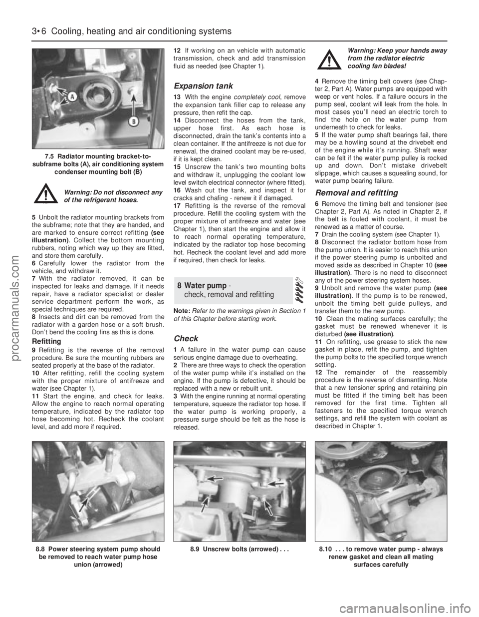
5Unbolt the radiator mounting brackets from
the subframe; note that they are handed, and
are marked to ensure correct refitting (see
illustration). Collect the bottom mounting
rubbers, noting which way up they are fitted,
and store them carefully.
6Carefully lower the radiator from the
vehicle, and withdraw it.
7With the radiator removed, it can be
inspected for leaks and damage. If it needs
repair, have a radiator specialist or dealer
service department perform the work, as
special techniques are required.
8Insects and dirt can be removed from the
radiator with a garden hose or a soft brush.
Don’t bend the cooling fins as this is done.
Refitting
9Refitting is the reverse of the removal
procedure. Be sure the mounting rubbers are
seated properly at the base of the radiator.
10After refitting, refill the cooling system
with the proper mixture of antifreeze and
water (see Chapter 1).
11Start the engine, and check for leaks.
Allow the engine to reach normal operating
temperature, indicated by the radiator top
hose becoming hot. Recheck the coolant
level, and add more if required.12If working on an vehicle with automatic
transmission, check and add transmission
fluid as needed (see Chapter 1).
Expansion tank
13With the engine completely cool, remove
the expansion tank filler cap to release any
pressure, then refit the cap.
14Disconnect the hoses from the tank,
upper hose first. As each hose is
disconnected, drain the tank’s contents into a
clean container. If the antifreeze is not due for
renewal, the drained coolant may be re-used,
if it is kept clean.
15Unscrew the tank’s two mounting bolts
and withdraw it, unplugging the coolant low
level switch electrical connector (where fitted).
16Wash out the tank, and inspect it for
cracks and chafing - renew it if damaged.
17Refitting is the reverse of the removal
procedure. Refill the cooling system with the
proper mixture of antifreeze and water (see
Chapter 1), then start the engine and allow it
to reach normal operating temperature,
indicated by the radiator top hose becoming
hot. Recheck the coolant level and add more
if required, then check for leaks.
Note:Refer to the warnings given in Section 1
of this Chapter before starting work.
Check
1A failure in the water pump can cause
serious engine damage due to overheating.
2There are three ways to check the operation
of the water pump while it’s installed on the
engine. If the pump is defective, it should be
replaced with a new or rebuilt unit.
3With the engine running at normal operating
temperature, squeeze the radiator top hose. If
the water pump is working properly, a
pressure surge should be felt as the hose is
released. Warning: Keep your hands away
from the radiator electric
cooling fan blades!
4Remove the timing belt covers (see Chap-
ter 2, Part A). Water pumps are equipped with
weep or vent holes. If a failure occurs in the
pump seal, coolant will leak from the hole. In
most cases you’ll need an electric torch to
find the hole on the water pump from
underneath to check for leaks.
5If the water pump shaft bearings fail, there
may be a howling sound at the drivebelt end
of the engine while it’s running. Shaft wear
can be felt if the water pump pulley is rocked
up and down. Don’t mistake drivebelt
slippage, which causes a squealing sound, for
water pump bearing failure.
Removal and refitting
6Remove the timing belt and tensioner (see
Chapter 2, Part A). As noted in Chapter 2, if
the belt is fouled with coolant, it must be
renewed as a matter of course.
7Drain the cooling system (see Chapter 1).
8Disconnect the radiator bottom hose from
the pump union. It is easier to reach this union
if the power steering pump is unbolted and
moved aside as described in Chapter 10 (see
illustration). There is no need to disconnect
any of the power steering system hoses.
9Unbolt and remove the water pump (see
illustration). If the pump is to be renewed,
unbolt the timing belt guide pulleys, and
transfer them to the new pump.
10Clean the mating surfaces carefully; the
gasket must be renewed whenever it is
disturbed (see illustration).
11On refitting, use grease to stick the new
gasket in place, refit the pump, and tighten
the pump bolts to the specified torque wrench
setting.
12The remainder of the reassembly
procedure is the reverse of dismantling. Note
that a new tensioner spring and retaining pin
must be fitted if the timing belt has been
removed for the first time. Tighten all
fasteners to the specified torque wrench
settings, and refill the system with coolant as
described in Chapter 1.
8 Water pump -
check, removal and refitting
3•6 Cooling, heating and air conditioning systems
7.5 Radiator mounting bracket-to-
subframe bolts (A), air conditioning system
condenser mounting bolt (B)
8.8 Power steering system pump should
be removed to reach water pump hose
union (arrowed)8.9 Unscrew bolts (arrowed) . . .8.10 . . . to remove water pump - always
renew gasket and clean all mating
surfaces carefully
procarmanuals.com
Page 97 of 279
the refrigerant. The liquid refrigerant boils off
into low-pressure vapour, taking the heat with
it when it leaves the evaporator.
Precautions
Warning: The air conditioning
system is under high pressure.
Do not loosen any fittings or
remove any components until
after the system has been discharged. Air
conditioning refrigerant should be properly
discharged into an approved type of
container, at a dealer service department
or an automotive air conditioning repair
facility capable of handling R134a
refrigerant. Always wear eye protection
when disconnecting air conditioning
system fittings.
When an air conditioning system is fitted, it
is necessary to observe the following special
precautions whenever dealing with any part of
the system, its associated components, and
any items which necessitate disconnection of
the system:
(a) While the refrigerant used - R134a - is
less damaging to the environment than
the previously-used R12, it is still a very
dangerous substance. It must not be
allowed into contact with the skin or eyes,
or there is a risk of frostbite. It must also
not be discharged in an enclosed space -
while it is not toxic, there is a risk of
suffocation. The refrigerant is heavier than
air, and so must never be discharged over
a pit.
(b) The refrigerant must not be allowed to
come in contact with a naked flame,
otherwise a poisonous gas will be created
- under certain circumstances, this can
form an explosive mixture with air. For
similar reasons, smoking in the presence
of refrigerant is highly dangerous,
particularly if the vapour is inhaled
through a lighted cigarette.
(c) Never discharge the system to the
atmosphere - R134a is not an ozone-
depleting ChloroFluoroCarbon (CFC) as is
R12, but is instead a hydrofluorocarbon,
which causes environmental damage by
contributing to the “greenhouse effect” if
released into the atmosphere.
(d) R134a refrigerant must notbe mixed with
R12; the system uses different seals (now
green-coloured, previously black) and has
different fittings requiring different tools,
so that there is no chance of the two
types of refrigerant becoming mixed
accidentally.
(e) If for any reason the system must be
disconnected, entrust this task to your
Ford dealer or a refrigeration engineer.
(f) It is essential that the system be
professionally discharged prior to using
any form of heat - welding, soldering,
brazing, etc - in the vicinity of the system,
before having the vehicle oven-dried at a
temperature exceeding 70°C after
repainting, and before disconnecting any
part of the system.Warning: The air conditioning
system is under high pressure.
Do not loosen any fittings or
remove any components until after the
system has been discharged. Air
conditioning refrigerant should be properly
discharged into an approved type of
container, at a dealer service department
or an automotive air conditioning repair
facility capable of handling R134a
refrigerant. Cap or plug the pipe lines as
soon as they are disconnected, to prevent
the entry of moisture. Always wear eye
protection when disconnecting air
conditioning system fittings.
Note: This Section refers to the components
of the air conditioning system itself - refer to
Sections 9 and 10 for details of components
common to the heating/ventilation system.
Condenser
1Have the refrigerant discharged at a dealer
service department or an automotive air
conditioning repair facility.
2Disconnect the battery negative (earth) lead
(see Chapter 5, Section 1).
3Remove the radiator undershield (see
Chapter 1).
4Using the Ford service tool 34-001,
disconnect the refrigerant lines from the
condenser. Immediately cap the open fittings,
to prevent the entry of dirt and moisture.
5Unbolt the condenser (see illustration 7.5)
and lift it out of the vehicle. Store it upright, to
prevent oil loss.
6Refitting is the reverse of removal.
7If a new condenser was installed, add 20 cc
of refrigerant oil to the system.
8Have the system evacuated, charged and
leak-tested by the specialist who discharged
it.
Evaporator
9The evaporator is mounted with the heater
matrix. Apart from the need to have the
refrigerant discharged, and to use Ford
service tools 34-001 and 34-003 to
disconnect the lines, the procedure is as
described in Section 9 of this Chapter.
10On reassembly, if a new evaporator was
installed, add 20 cc of refrigerant oil to the
system.
11Have the system evacuated, charged and
leak-tested by the specialist who discharged
it.
Compressor
12Have the refrigerant discharged at a
dealer service department or an automotive
air conditioning repair facility.
13Disconnect the battery negative (earth)
lead (see Chapter 5, Section 1).
14Remove the radiator undershield (see
Chapter 1).15Remove the auxiliary drivebelt (see
Chapter 1).
16Unbolt the compressor from the cylinder
block/crankcase, press it to one side, and
unscrew the clamping bolt to disconnect the
refrigerant lines. Plug the line connections,
swing the compressor upright, unplug its
electrical connector, then withdraw the
compressor from the vehicle. Note:Keep the
compressor level during handling and storage.
If the compressor has seized, or if you find
metal particles in the refrigerant lines, the
system must be flushed out by an air
conditioning technician, and the
accumulator/dehydrator must be renewed.
17Prior to installation, turn the compressor
clutch centre six times, to disperse any oil that
has collected in the head.
18Refit the compressor in the reverse order
of removal; renew all seals disturbed.
19If you are installing a new compressor,
refer to the compressor manufacturer’s
instructions for adding refrigerant oil to the
system.
20Have the system evacuated, charged and
leak-tested by the specialist that discharged
it.
Accumulator/dehydrator
21Have the refrigerant discharged at a
dealer service department or an automotive
air conditioning repair facility.
22Disconnect the battery negative (earth)
lead (see Chapter 5, Section 1).
23The accumulator/dehydrator, which acts
as a reservoir and filter for the refrigerant, is
located in the left-hand front corner of the
engine compartment. Using the Ford service
tool 34-003, disconnect the refrigerant line
next to the accumulator/dehydrator from the
compressor. Immediately cap the open
fittings, to prevent the entry of dirt and
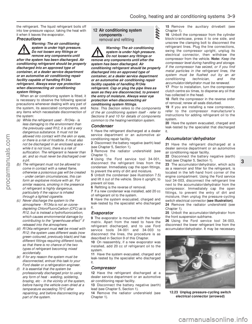
moisture, then unplug the pressure-cycling
switch electrical connector (see illustration).
24Remove the radiator undershield (see
Chapter 1).
25Unbolt the accumulator/dehydrator from
the front suspension subframe.
26Using the Ford service tool 34-003,
disconnect the lower refrigerant line from the
accumulator/dehydrator. It may be necessary
12 Air conditioning system
components -
removal and refitting
Cooling, heating and air conditioning systems 3•9
3
12.23 Unplug pressure-cycling switch
electrical connector (arrowed)
procarmanuals.com
Page 140 of 279
back again, as an assistant depresses the
accelerator pedal. If the valve shows any sign
of stiffness, sticking or otherwise-inhibited
movement (and the accelerator cable is
known from the previous check to be in good
condition), spray the throttle linkage with
penetrating lubricant, allow time for it to work,
and repeat the check; if no improvement is
obtained, the complete throttle housing must
be renewed (Chapter 4).
15Unclip the air cleaner cover, and check
that the air filter element and the crankcase
ventilation system filter are not clogged or
soaked. (A clogged air filter will obstruct the
intake air flow, causing a noticeable effect on
engine performance; a clogged crankcase
ventilation system filter will inhibit crankcase
“breathing”). Renew or clean the filter(s) as
appropriate; refer to the relevant Sections of
Chapter 1 for further information, if required.
Before refitting the air cleaner cover, check
that the air intake (located under the front left-
hand wing, opening behind the direction
indicator/headlight assembly) is clear. It
should be possible to blow through the intake,
or to probe it (carefully) as far as the rear of
the direction indicator light.
16Start the engine and allow it to idle.
Note:Working in the engine compartment
while the engine is running requires great care
if the risk of personal injury is to be avoided;
among the dangers are burns from contact
with hot components, or contact with moving
components such as the radiator cooling fan
or the auxiliary drivebelt. Refer to “Safety
first!” at the front of this manual before
starting, and ensure that your hands, and long
hair or loose clothing, are kept well clear of hot
or moving components at all times.
17Working from the air intake junction at the
inner wing panel, via the air cleaner assembly
and air mass meter, to the resonator, plenum
chamber, throttle housing and inlet manifold
(and including the various vacuum hoses and
pipes connected to these), check for air leaks.
Usually, these will be revealed by sucking or
hissing noises, but minor leaks may be traced
by spraying a solution of soapy water on to
the suspect joint; if a leak exists, it will be
shown by the change in engine note and the
accompanying air bubbles (or sucking-in of
the liquid, depending on the pressure
difference at that point). If a leak is found at
any point, tighten the fastening clamp and/or
renew the faulty components, as applicable.
18Similarly, work from the cylinder head, via
the manifold (and not forgetting the related
EGR and pulse-air system components) to the
tailpipe, to check that the exhaust system is
free from leaks. The simplest way of doing
this, if the vehicle can be raised and
supported safely and with complete security
while the check is made, is to temporarily
block the tailpipe while listening for the sound
of escaping exhaust gases; any leak should
be evident. If a leak is found at any point,
tighten the fastening clamp bolts and/or nuts,
renew the gasket, and/or renew the faultysection of the system, as necessary, to seal
the leak.
19It is possible to make a further check of
the electrical connections by wiggling each
electrical connector of the system in turn as
the engine is idling; a faulty connector will be
immediately evident from the engine’s
response as contact is broken and remade. A
faulty connector should be renewed to ensure
the future reliability of the system; note that
this may mean the renewal of that entire
section of the loom - see your local Ford
dealer for details.
20Switch off the engine. If the fault is not yet
identified, the next step is to check the
ignition voltages, using an engine analyser
with an oscilloscope - without such
equipment, the only tests possible are to
remove and check each spark plug in turn, to
check the spark plug (HT) lead connections
and resistances, and to check the
connections and resistances of the ignition
coil. Refer to the relevant Sections of
Chapters 1 and 5.
21The final step in these preliminary checks
would be to use an exhaust gas analyser to
measure the CO level at the exhaust tailpipe.This check cannot be made without special
test equipment - see your local Ford dealer for
details.
Fault code read-out
22As noted in the general comments at the
beginning of this Section, the preliminary
checks outlined above should eliminate the
majority of faults from the engine
management system. If the fault is not yet
identified, the next step is to connect a fault
code reader to the ECU, so that its self-
diagnosis facility can be used to identify the
faulty part of the system; further tests can
then be made to identify the exact cause of
the fault.
23In their basic form, fault code readers are
simply hand-held electronic devices, which
take data stored within an ECU’s memory and
display it when required as two- or three-digit
fault codes. The more sophisticated versions
now available can also control sensors and
actuators, to provide more effective testing;
some can store information, so that a road
test can be carried out, and any faults
encountered during the test can be displayed
afterwards.
6•6 Emissions control systems
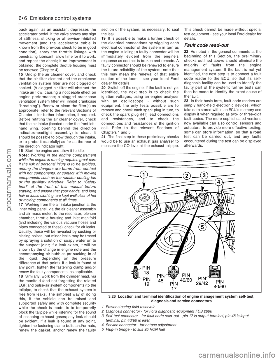
3.26 Location and terminal identification of engine management system self-test,
diagnosis and service connectors
1 Power steering fluid reservoir
2 Diagnosis connector - for Ford diagnostic equipment FDS 2000
3 Self-test connector - for fault code read-out - pin 17 is output terminal, pin 48 is input
terminal, pin 40/60 is earth
4 Service connector - for octane adjustment
5 Plug-in bridge - to suit 95 RON fuel
procarmanuals.com
Page 144 of 279
Ignition timing and base idle
speed check
Note:The following procedure is a check only,
essentially of the ECU. Both the ignition timing
and the base idle speed are controlled by the
ECU. The ignition timing is not adjustable at
all; the base idle speed is set in production,
and should not be altered.
38If the fault code read-out (with any checks
resulting from it) has not eliminated the fault,
the next step is to check the ECU’s control of
the ignition timing and the base idle speed.
This task requires the use of a Ford STAR
tester (a proprietary fault code reader can be
used only if it is capable of inducing the ECU
to enter its “Service Adjustment Programme”),
coupled with an accurate tachometer and a
good-quality timing light. Without this
equipment, the task is not possible; the
vehicle must be taken to a Ford dealer for
attention.
39To make the check, apply the handbrake,
switch off the air conditioning (where fitted)
and any other electrical loads (lights, heated
rear window, etc), then select neutral (manual
transmission) or the “P” position (automatic
transmission). Start the engine, and warm it
up to normal operating temperature. The
radiator electric cooling fan must be running
continuously while the check is made; this
should be activated by the ECU, when
prompted by the tester. Switch off the engine,
and connect the test equipment as directed
by the manufacturer - refer to paragraph 26
above for details of STAR tester connection.
40Raise and support the front of the vehicle
securely, and remove the auxiliary drivebelt
cover (see Chapter 1). Emphasise the two
pairs of notches in the inner and outer rims of
the crankshaft pulley, using white paint. Note
that an ignition timing reference mark is not
provided on the pulley - in the normal
direction of crankshaft rotation (clockwise,
seen from the right-hand side of the vehicle)
the first pair of notches are irrelevant to the
vehicles covered in this manual, while the
second pair indicate Top Dead Centre (TDC)
when aligned with the rear edge of the raised
mark on the sump; when checking the ignition
timing, therefore, the (rear edge of the) sumpmark should appear just before the TDC
notches (see Part A of Chapter 2, Section 4,
for further information if required).
41Start the engine and allow it to idle. Work
through the engine-running test procedure
until the ECU enters its “Service Adjustment
Programme” - see paragraph 35 above.
42Use the timing light to check that the
timing marks appear approximately as
outlined above at idle speed. Do not spend
too much time on this check; if the timing
appears to be incorrect, the system may have
a fault, and a full system test must be carried
out (see below) to establish its cause.
43Using the tachometer, check that the
base idle speed is as given in the
Specifications Section of Chapter 4.
44If the recorded speed differs significantly
from the specified value, check for air leaks,
as described in the preliminary checks
(paragraphs 15 to 18 above), or any other
faults which might cause the discrepancy.
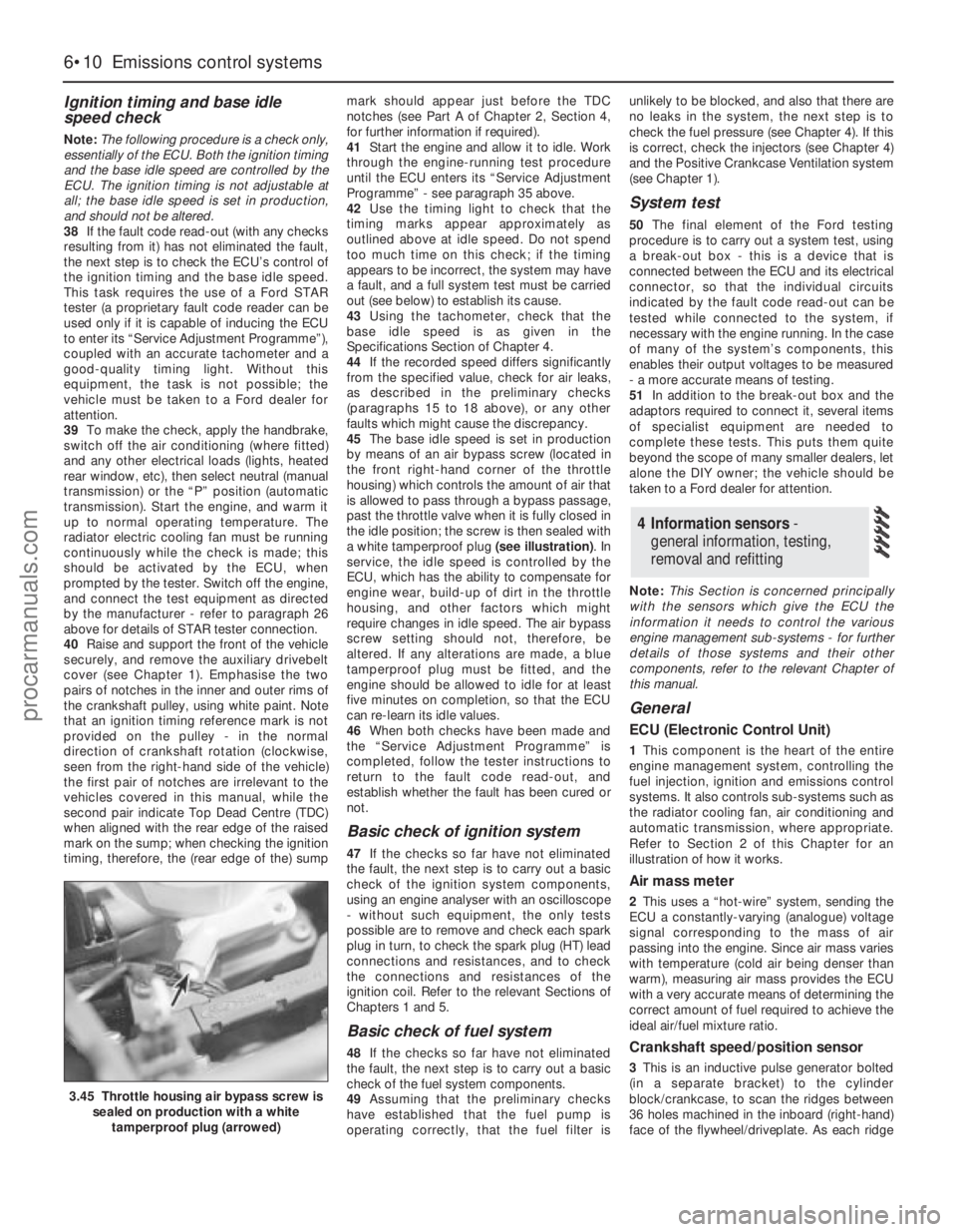
45The base idle speed is set in production
by means of an air bypass screw (located in
the front right-hand corner of the throttle
housing) which controls the amount of air that
is allowed to pass through a bypass passage,
past the throttle valve when it is fully closed in
the idle position; the screw is then sealed with
a white tamperproof plug (see illustration). In
service, the idle speed is controlled by the
ECU, which has the ability to compensate for
engine wear, build-up of dirt in the throttle
housing, and other factors which might
require changes in idle speed. The air bypass
screw setting should not, therefore, be
altered. If any alterations are made, a blue
tamperproof plug must be fitted, and the
engine should be allowed to idle for at least
five minutes on completion, so that the ECU
can re-learn its idle values.
46When both checks have been made and
the “Service Adjustment Programme” is
completed, follow the tester instructions to
return to the fault code read-out, and
establish whether the fault has been cured or
not.
Basic check of ignition system
47If the checks so far have not eliminated
the fault, the next step is to carry out a basic
check of the ignition system components,
using an engine analyser with an oscilloscope
- without such equipment, the only tests
possible are to remove and check each spark
plug in turn, to check the spark plug (HT) lead
connections and resistances, and to check
the connections and resistances of the
ignition coil. Refer to the relevant Sections of
Chapters 1 and 5.
Basic check of fuel system
48If the checks so far have not eliminated
the fault, the next step is to carry out a basic
check of the fuel system components.
49Assuming that the preliminary checks
have established that the fuel pump is
operating correctly, that the fuel filter isunlikely to be blocked, and also that there are
no leaks in the system, the next step is to
check the fuel pressure (see Chapter 4). If this
is correct, check the injectors (see Chapter 4)
and the Positive Crankcase Ventilation system
(see Chapter 1).
System test
50The final element of the Ford testing
procedure is to carry out a system test, using
a break-out box - this is a device that is
connected between the ECU and its electrical
connector, so that the individual circuits
indicated by the fault code read-out can be
tested while connected to the system, if
necessary with the engine running. In the case
of many of the system’s components, this
enables their output voltages to be measured
- a more accurate means of testing.
51In addition to the break-out box and the
adaptors required to connect it, several items
of specialist equipment are needed to
complete these tests. This puts them quite
beyond the scope of many smaller dealers, let
alone the DIY owner; the vehicle should be
taken to a Ford dealer for attention.
Note:This Section is concerned principally
with the sensors which give the ECU the
information it needs to control the various
engine management sub-systems - for further
details of those systems and their other
components, refer to the relevant Chapter of
this manual.
General
ECU (Electronic Control Unit)
1This component is the heart of the entire
engine management system, controlling the
fuel injection, ignition and emissions control
systems. It also controls sub-systems such as
the radiator cooling fan, air conditioning and
automatic transmission, where appropriate.
Refer to Section 2 of this Chapter for an
illustration of how it works.
Air mass meter
2This uses a “hot-wire” system, sending the
ECU a constantly-varying (analogue) voltage
signal corresponding to the mass of air
passing into the engine. Since air mass varies
with temperature (cold air being denser than
warm), measuring air mass provides the ECU
with a very accurate means of determining the
correct amount of fuel required to achieve the
ideal air/fuel mixture ratio.
Crankshaft speed/position sensor
3This is an inductive pulse generator bolted
(in a separate bracket) to the cylinder
block/crankcase, to scan the ridges between
36 holes machined in the inboard (right-hand)
face of the flywheel/driveplate. As each ridge
4 Information sensors -
general information, testing,
removal and refitting
6•10 Emissions control systems
3.45 Throttle housing air bypass screw is
sealed on production with a white
tamperproof plug (arrowed)
procarmanuals.com
Page 205 of 279
compartment, but on Estate models, it is on
the right-hand side.
Some models are fitted with a headlight
levelling system, which is controlled by a knob
on the facia. On position “0”, the headlights
are in their base position, and on position “5”,
the headlights are in their maximum inclined
angle.
It should be noted that, when portions of
the electrical system are serviced, the cable
should be disconnected from the battery
negative terminal, to prevent electrical shorts
and fires.
Caution: When disconnecting the
battery for work described in the
following Sections, refer to
Chapter 5, Section 1.
Note:Refer to the precautions given in
“Safety first!” and in Section 1 of this Chapter
before starting work. The following tests relate
to testing of the main electrical circuits, and
should not be used to test delicate electronic
circuits (such as engine management systems,
anti-lock braking systems, etc), particularly
where an electronic control module is used.
Also refer to the precautions given in Chapter
5, Section 1.
General
1A typical electrical circuit consists of an
electrical component, any switches, relays,
motors, fuses, fusible links or circuit breakers
related to that component, and the wiring and
connectors which link the component to both
the battery and the chassis. To help to
pinpoint a problem in an electrical circuit,
wiring diagrams are included at the end of this
manual.
2Before attempting to diagnose an electrical
fault, first study the appropriate wiring
diagram, to obtain a complete understanding
of the components included in the particular
circuit concerned. The possible sources of a
fault can be narrowed down by noting if other
components related to the circuit are
operating properly. If several components or
circuits fail at one time, the problem is likely to
be related to a shared fuse or earth
connection.
3Electrical problems usually stem from
simple causes, such as loose or corroded
connections, a faulty earth connection, a
blown fuse, a melted fusible link, or a faulty
relay (refer to Section 3 for details of testing
relays). Visually inspect the condition of all
fuses, wires and connections in a problem
circuit before testing the components. Use
the wiring diagrams to determine which
terminal connections will need to be checked
in order to pinpoint the trouble-spot.
4The basic tools required for electrical fault-
finding include a circuit tester or voltmeter (a
12-volt bulb with a set of test leads can alsobe used for certain tests); an ohmmeter (to
measure resistance and check for continuity);
a battery and set of test leads; and a jumper
wire, preferably with a circuit breaker or fuse
incorporated, which can be used to bypass
suspect wires or electrical components.
Before attempting to locate a problem with
test instruments, use the wiring diagram to
determine where to make the connections.
5To find the source of an intermittent wiring
fault (usually due to a poor or dirty
connection, or damaged wiring insulation), a
“wiggle” test can be performed on the wiring.
This involves wiggling the wiring by hand to
see if the fault occurs as the wiring is moved.
It should be possible to narrow down the
source of the fault to a particular section of
wiring. This method of testing can be used in
conjunction with any of the tests described in
the following sub-Sections.
6Apart from problems due to poor
connections, two basic types of fault can
occur in an electrical circuit - open-circuit, or
short-circuit.
7Open-circuit faults are caused by a break
somewhere in the circuit, which prevents
current from flowing. An open-circuit fault will
prevent a component from working.
8Short-circuit faults are caused by a “short”
somewhere in the circuit, which allows the
current flowing in the circuit to “escape” along
an alternative route, usually to earth. Short-
circuit faults are normally caused by a
breakdown in wiring insulation, which allows a
feed wire to touch either another wire, or an
earthed component such as the bodyshell. A
short-circuit fault will normally cause the
relevant circuit fuse to blow.
Finding an open-circuit
9To check for an open-circuit, connect one
lead of a circuit tester or the negative lead of a
voltmeter either to the battery negative
terminal or to a known good earth.
10Connect the other lead to a connector in
the circuit being tested, preferably nearest to
the battery or fuse. At this point, battery
voltage should be present, unless the lead
from the battery or the fuse itself is faulty
(bearing in mind that some circuits are live
only when the ignition switch is moved to a
particular position).
11Switch on the circuit, then connect the
tester lead to the connector nearest the circuit
switch on the component side.
12If voltage is present (indicated either by
the tester bulb lighting or a voltmeter reading,
as applicable), this means that the section of
the circuit between the relevant connector
and the switch is problem-free.
13Continue to check the remainder of the
circuit in the same fashion.
14When a point is reached at which no
voltage is present, the problem must lie
between that point and the previous test point
with voltage. Most problems can be traced to
a broken, corroded or loose connection.
Finding a short-circuit
15To check for a short-circuit, first
disconnect the load(s) from the circuit (loads
are the components which draw current from
a circuit, such as bulbs, motors, heating
elements, etc).
16Remove the relevant fuse from the circuit,
and connect a circuit tester or voltmeter to the
fuse connections.
17Switch on the circuit, bearing in mind that
some circuits are live only when the ignition
switch is moved to a particular position.
18If voltage is present (indicated either by
the tester bulb lighting or a voltmeter reading,
as applicable), this means that there is a
short-circuit.
19If no voltage is present during this test,
but the fuse still blows with the load(s)
reconnected, this indicates an internal fault in
the load(s).
Finding an earth fault
20The battery negative terminal is
connected to “earth” - the metal of the
engine/transmission unit and the vehicle body
- and many systems are wired so that they
only receive a positive feed, the current
returning via the metal of the car body. This
means that the component mounting and the
body form part of that circuit. Loose or
corroded mountings can therefore cause a
range of electrical faults, ranging from total
failure of a circuit, to a puzzling partial failure.
In particular, lights may shine dimly (especially
when another circuit sharing the same earth
point is in operation), motors (eg wiper motors
or the radiator cooling fan motor) may run
slowly, and the operation of one circuit may
have an apparently-unrelated effect on
another. Note that on many vehicles, earth
straps are used between certain components,
such as the engine/transmission and the
body, usually where there is no metal-to-
metal contact between components, due to
flexible rubber mountings, etc.
21To check whether a component is
properly earthed, disconnect the battery (refer
to Chapter 5, Section 1) and connect one lead
of an ohmmeter to a known good earth point.
Connect the other lead to the wire or earth
connection being tested. The resistance
reading should be zero; if not, check the
connection as follows.
22If an earth connection is thought to be
faulty, dismantle the connection, and clean
both the bodyshell and the wire terminal (or
the component earth connection mating
surface) back to bare metal. Be careful to
remove all traces of dirt and corrosion, then
use a knife to trim away any paint, so that a
clean metal-to-metal joint is made. On
reassembly, tighten the joint fasteners
securely; if a wire terminal is being refitted,
use serrated washers between the terminal
and the bodyshell, to ensure a clean and
secure connection. When the connection is
2 Electrical fault finding -
general information
12•4 Body electrical system
procarmanuals.com