1993 FORD MONDEO radiator cap
[x] Cancel search: radiator capPage 216 of 279
6Similarly remove the fuel gauge and
temperature gauge by unscrewing the single
screws.
7Remove all the pin contacts.
8Using a small punch, push in the multi-plug
securing pins, and remove the multi-plugs.
9Carefully lift the printed circuit from the
location dowels on the housing, taking care
not to damage it.
Refitting
10Refitting is a reversal of the removal
procedure.
Removal
1Remove the windscreen wiper arms as
described in Section 15.
2With the bonnet closed, release the grille
panel upper edge from just in front of the
windscreen, by prising off the caps and
unscrewing the upper retaining screws.
3Open the bonnet, and support with the
stay.
4Pull off the sealing strip from the cross
panel at the rear of the engine compartment.
5Unscrew the lower screws, and remove the
grille panel halves from in front of thewindscreen, withdrawing first one side and
then the other.
6Disconnect the battery negative (earth) lead
(refer to Chapter 5, Section 1).
7Reach in behind the bulkhead. Squeeze the
collar on the upper end of the speedometer
cable, where it is attached to the intermediate
cable from the rear of the speedometer head.
Disconnect the cable, and withdraw it from
the bulkhead inner panel, together with the
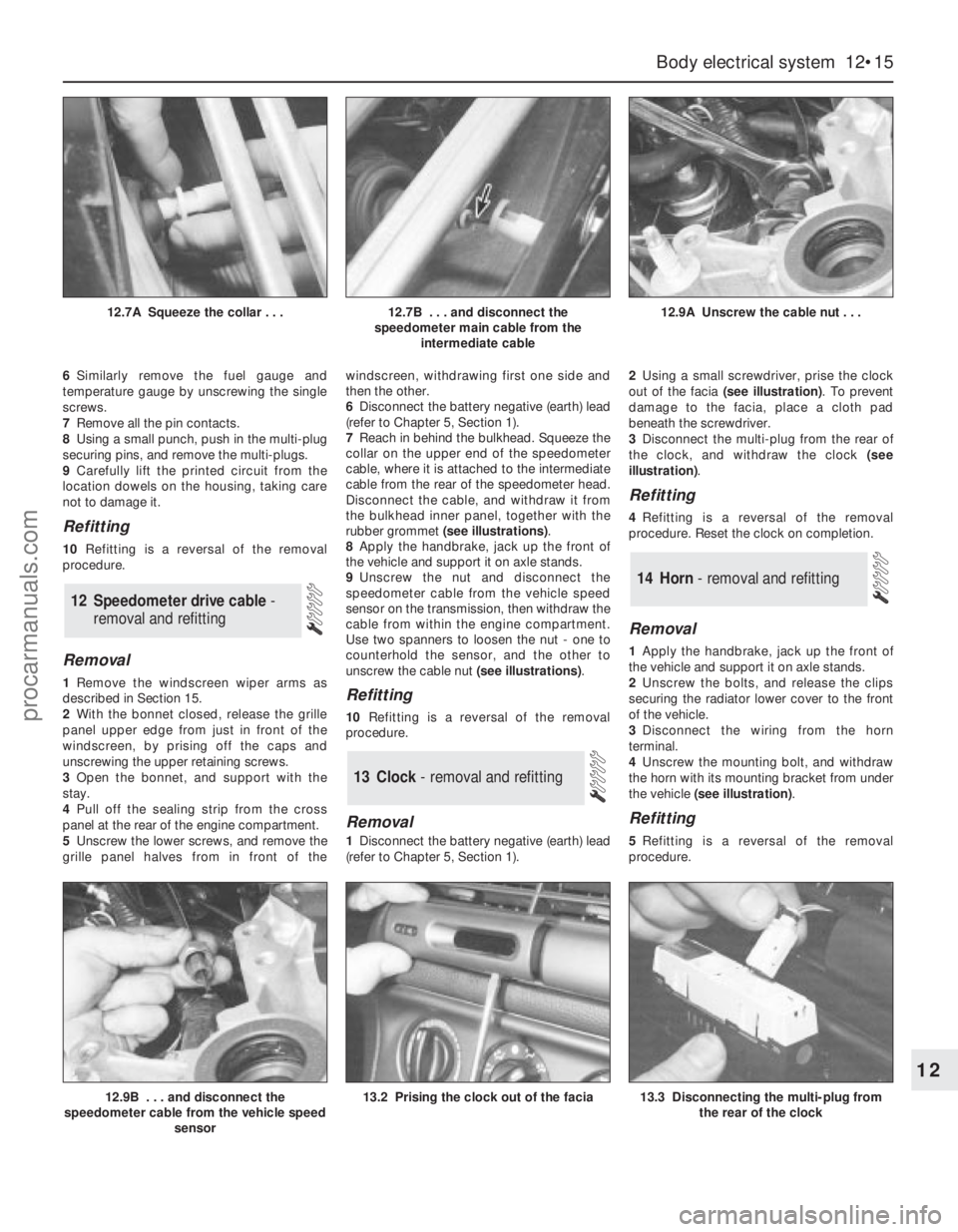
rubber grommet (see illustrations).
8Apply the handbrake, jack up the front of
the vehicle and support it on axle stands.
9Unscrew the nut and disconnect the
speedometer cable from the vehicle speed
sensor on the transmission, then withdraw the
cable from within the engine compartment.
Use two spanners to loosen the nut - one to
counterhold the sensor, and the other to
unscrew the cable nut (see illustrations).Refitting
10Refitting is a reversal of the removal
procedure.
Removal
1Disconnect the battery negative (earth) lead
(refer to Chapter 5, Section 1).2Using a small screwdriver, prise the clock
out of the facia (see illustration). To prevent
damage to the facia, place a cloth pad
beneath the screwdriver.
3Disconnect the multi-plug from the rear of
the clock, and withdraw the clock (see
illustration).
Refitting
4Refitting is a reversal of the removal
procedure. Reset the clock on completion.
Removal
1Apply the handbrake, jack up the front of
the vehicle and support it on axle stands.
2Unscrew the bolts, and release the clips
securing the radiator lower cover to the front
of the vehicle.
3Disconnect the wiring from the horn
terminal.
4Unscrew the mounting bolt, and withdraw
the horn with its mounting bracket from under
the vehicle (see illustration).
Refitting
5Refitting is a reversal of the removal
procedure.
14 Horn - removal and refitting
13 Clock- removal and refitting
12 Speedometer drive cable -
removal and refitting
Body electrical system 12•15
12
12.9B . . . and disconnect the
speedometer cable from the vehicle speed
sensor13.2 Prising the clock out of the facia13.3 Disconnecting the multi-plug from
the rear of the clock
12.7A Squeeze the collar . . .12.7B . . . and disconnect the
speedometer main cable from the
intermediate cable12.9A Unscrew the cable nut . . .
procarmanuals.com
Page 221 of 279
switches mounted in the engine compartment
with a control cable connected to the throttle
valve actuator, driver-operated switches,
brake and clutch pedal switches, an indicator
light, and a road speed sensor.
4The driver-operated switches are mounted
on the steering wheel, and allow the driver to
control the various functions.
5The vehicle speed sensor uses the
speedometer cable drive pinion to generate
pulses which are fed to the speed control unit.
6The stop-light switch, brake pedal switch
and (when applicable) clutch pedal switch are
used to disable the cruise control system. The
stop-light switch is activated when the brake
pedal is applied gently, and the brake pedal
switch is activated when the brake pedal is
applied forcibly.
7An indicator light on the instrument panel is
illuminated when the system is in operation.
8The following paragraphs describe brief
removal procedures for the cruise control
system components. The battery negative
(earth) lead should be disconnected before
commencing work (refer to Chapter 5, Sec-
tion 1). Refitting is a reversal of removal.
Speed control switch
9Remove the steering column upper and
lower shrouds, with reference to Chapter 10.
10Remove the air bag module as described
in Section 29.11Disconnect the multi-plugs, then unscrew
the screws and remove the switch.
Disable switches
12Remove the lower facia panel from under
the steering column.
13Disconnect the multi-plugs from the
clutch switch, brake pedal switch and stop-
light switch.
14To remove the clutch and brake pedal
switches, twist them anti-clockwise. To
remove the stop-light switch, twist it
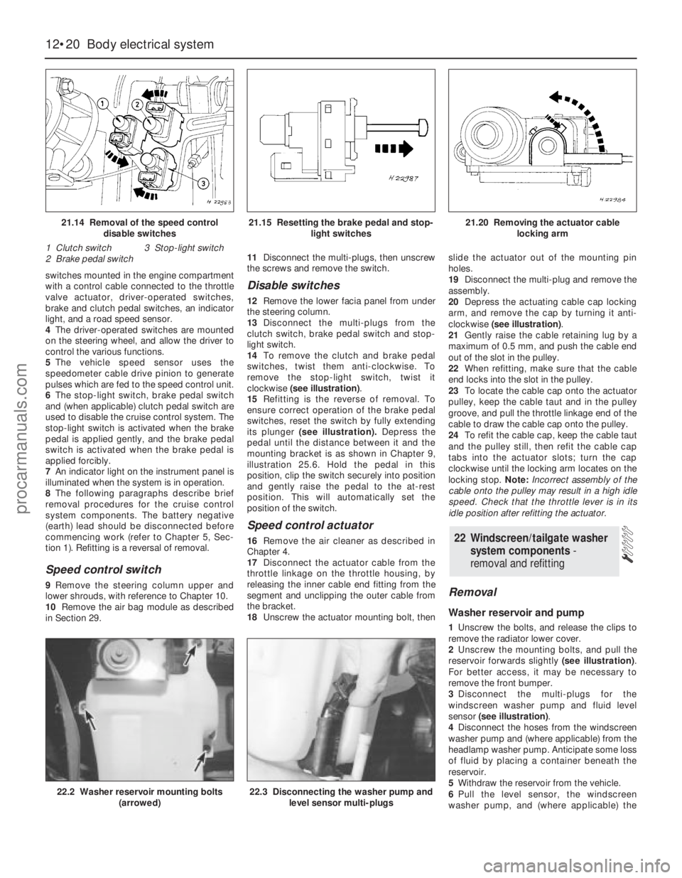
clockwise (see illustration).
15Refitting is the reverse of removal. To
ensure correct operation of the brake pedal
switches, reset the switch by fully extending
its plunger (see illustration).Depress the
pedal until the distance between it and the
mounting bracket is as shown in Chapter 9,
illustration 25.6. Hold the pedal in this
position, clip the switch securely into position
and gently raise the pedal to the at-rest
position. This will automatically set the
position of the switch.
Speed control actuator
16Remove the air cleaner as described in
Chapter 4.
17Disconnect the actuator cable from the
throttle linkage on the throttle housing, by
releasing the inner cable end fitting from the
segment and unclipping the outer cable from
the bracket.
18Unscrew the actuator mounting bolt, thenslide the actuator out of the mounting pin
holes.
19Disconnect the multi-plug and remove the
assembly.
20Depress the actuating cable cap locking
arm, and remove the cap by turning it anti-
clockwise (see illustration).
21Gently raise the cable retaining lug by a
maximum of 0.5 mm, and push the cable end
out of the slot in the pulley.
22When refitting, make sure that the cable
end locks into the slot in the pulley.
23To locate the cable cap onto the actuator
pulley, keep the cable taut and in the pulley
groove, and pull the throttle linkage end of the
cable to draw the cable cap onto the pulley.
24To refit the cable cap, keep the cable taut
and the pulley still, then refit the cable cap
tabs into the actuator slots; turn the cap
clockwise until the locking arm locates on the
locking stop. Note:Incorrect assembly of the
cable onto the pulley may result in a high idle
speed. Check that the throttle lever is in its
idle position after refitting the actuator.
Removal
Washer reservoir and pump
1Unscrew the bolts, and release the clips to
remove the radiator lower cover.
2Unscrew the mounting bolts, and pull the
reservoir forwards slightly (see illustration).
For better access, it may be necessary to
remove the front bumper.
3Disconnect the multi-plugs for the
windscreen washer pump and fluid level
sensor (see illustration).
4Disconnect the hoses from the windscreen
washer pump and (where applicable) from the
headlamp washer pump. Anticipate some loss
of fluid by placing a container beneath the
reservoir.
5Withdraw the reservoir from the vehicle.
6Pull the level sensor, the windscreen
washer pump, and (where applicable) the
22 Windscreen/tailgate washer
system components -
removal and refitting
12•20 Body electrical system
21.14 Removal of the speed control
disable switches
1 Clutch switch 3 Stop-light switch
2 Brake pedal switch21.15 Resetting the brake pedal and stop-
light switches21.20 Removing the actuator cable
locking arm
22.2 Washer reservoir mounting bolts
(arrowed)22.3 Disconnecting the washer pump and
level sensor multi-plugs
procarmanuals.com
Page 267 of 279
Engine misfires throughout the driving speed range
m mFuel filter choked (Chapter 1).
m mFuel pump faulty or delivery pressure low (Chapter 4).
m mFuel tank vent blocked or fuel pipes restricted (Chapter 4).
m mVacuum leak at the inlet manifold or associated hoses (Chap-
ters 1, 4 and 6).
m mWorn, faulty or incorrectly-gapped spark plugs (Chapter 1).
m mFaulty spark plug HT leads (Chapter 1).
m mFaulty ignition coil (Chapter 5).
m mEngine management system fault (Chapters 1, 4, 5 and 6)
m mUneven or low cylinder compressions (Chapter 2, Part A).
Engine hesitates on acceleration
m
mWorn, faulty or incorrectly-gapped spark plugs (Chapter 1).
m mEngine management system fault (Chapters 1, 4, 5 and 6).
m mVacuum leak at the inlet manifold or associated hoses (Chap-
ters 1, 4 and 6).
Engine stalls
m mIdle speed control valve faulty (Chapter 4).
m mEngine management system fault (Chapters 1, 4, 5 and 6).
m mVacuum leak at the inlet manifold or associated hoses (Chap-
ters 1, 4 and 6).
m mFuel filter choked (Chapter 1).
m mFuel pump faulty or delivery pressure low (Chapter 4).
m mFuel tank vent blocked or fuel pipes restricted (Chapter 4).
Engine lacks power
m
mIncorrect ignition timing (Chapters 5 and 6).
m mEngine management system fault (Chapters 1, 4, 5 and 6).
m mTiming belt incorrectly fitted or incorrectly tensioned (Chapter 2,
Part A).
m mFuel filter choked (Chapter 1).
m mFuel pump faulty or delivery pressure low (Chapter 4).
m mUneven or low cylinder compressions (Chapter 2, Part A).
m mWorn, faulty or incorrectly-gapped spark plugs (Chapter 1).
m mVacuum leak at the inlet manifold or associated hoses (Chap-
ters 1, 4 and 6).
m mBrakes binding (Chapters 1 and 9).
m mClutch slipping (Chapter 8).
m mAutomatic transmission fluid level incorrect (Chapter 1).
Engine runs-on after switching off
m
mIdle speed excessively high (Chapters 4 and 6).
m mEngine management system fault (Chapters 1, 4, 5 and 6).
m mExcessive carbon build-up in engine (Chapter 2, Part A).
m mHigh engine operating temperature (Chapter 3).
Engine backfires
m
mIgnition timing incorrect (Chapters 5 and 6).
m mEngine management system fault (Chapters 1, 4, 5 and 6).
m mTiming belt incorrectly fitted or incorrectly tensioned (Chapter 2,
Part A).
m mVacuum leak at the inlet manifold or associated hoses (Chap-
ters 1, 4 and 6).
Oil pressure warning light illuminated with engine
running
m mLow oil level or incorrect oil grade (Chapter 1).
m mFaulty oil pressure warning light switch (Chapter 2, Part A).
m mWorn engine bearings and/or oil pump (Chapter 2).
m mHigh engine operating temperature (Chapter 3).
m mOil pressure relief valve defective (Chapter 2, Part A).
m mOil pick-up strainer clogged (Chapter 2, Part A).
Engine noises
Pre-ignition (pinking) or knocking during acceleration or under
load
m mIgnition timing incorrect (Chapters 5 and 6).
m mIncorrect grade of fuel (Chapter 4).
m mVacuum leak at the inlet manifold or associated hoses (Chap-
ters 1, 4 and 6).
m mExcessive carbon build-up in engine (Chapter 2, Part A).
Whistling or wheezing noises
m mLeaking inlet manifold gasket (Chapter 2, Part A).
m mLeaking exhaust manifold gasket or downpipe-to-manifold joint
(Chapters 1, 2 Part A, and 4).
m mLeaking vacuum hose (Chapters 1, 4, 6 and 9).
m mBlowing cylinder head gasket (Chapter 2, Part A).
Tapping or rattling noises
m mFaulty hydraulic tappet(s) (Chapter 2, Part A).
m mWorn valve gear or camshaft (Chapter 2, Part A).
m mWorn timing belt or tensioner (Chapter 2, Part A).
m mAncillary component fault (water pump, alternator, etc) (Chap-
ters 3 and 5).
Knocking or thumping noises
m mWorn big-end bearings (regular heavy knocking, perhaps less
under load) (Chapter 2, Part B).
m mWorn main bearings (rumbling and knocking, perhaps worsening
under load) (Chapter 2, Part B).
m mPiston slap (most noticeable when cold) (Chapter 2, Part B).
m mAncillary component fault (water pump, alternator, etc) (Chap-
ters 3 and 5).
REF•8Fault Finding
2 Cooling system
Overheating
m mInsufficient coolant in system (Chapter 1).
m mThermostat faulty (Chapter 3).
m mRadiator core blocked or grille restricted (Chapter 3).
m mRadiator electric cooling fan(s) or coolant temperature sensor faulty
(Chapter 3).
m mEngine management system fault (Chapters 1, 4, 5 and 6).
m mPressure cap faulty (Chapter 3).
m mAuxiliary drivebelt worn or slipping (Chapter 1).
m mIgnition timing incorrect (Chapters 5 and 6).
m mInaccurate coolant temperature gauge sender (Chapter 3).
m mAir-lock in cooling system (Chapter 1).
Overcooling
m
mThermostat faulty (Chapter 3).
m mInaccurate coolant temperature gauge sender (Chapter 3).
External coolant leakage
m
mDeteriorated or damaged hoses or hose clips (Chapter 1).
m mRadiator core or heater matrix leaking (Chapter 3).
m mPressure cap faulty (Chapter 3).
m mWater pump seal leaking (Chapter 3).
m mBoiling due to overheating (Chapter 3).
m mCore plug leaking (Chapter 2, Part B).
procarmanuals.com
Page 274 of 279
REF•15Glossary of Technical Terms
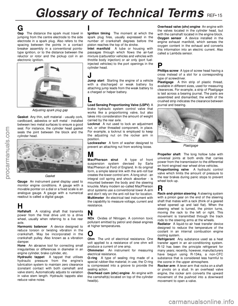
GGapThe distance the spark must travel in
jumping from the centre electrode to the side
electrode in a spark plug. Also refers to the
spacing between the points in a contact
breaker assembly in a conventional points-
type ignition, or to the distance between the
reluctor or rotor and the pickup coil in an
electronic ignition.
GasketAny thin, soft material - usually cork,
cardboard, asbestos or soft metal - installed
between two metal surfaces to ensure a good
seal. For instance, the cylinder head gasket
seals the joint between the block and the
cylinder head.
GaugeAn instrument panel display used to
monitor engine conditions. A gauge with a
movable pointer on a dial or a fixed scale is an
analogue gauge. A gauge with a numerical
readout is called a digital gauge.
HHalfshaftA rotating shaft that transmits
power from the final drive unit to a drive
wheel, usually when referring to a live rear
axle.
Harmonic balancerA device designed to
reduce torsion or twisting vibration in the
crankshaft. May be incorporated in the
crankshaft pulley. Also known as a vibration
damper.
HoneAn abrasive tool for correcting small
irregularities or differences in diameter in an
engine cylinder, brake cylinder, etc.
Hydraulic tappetA tappet that utilises
hydraulic pressure from the engine’s
lubrication system to maintain zero clearance
(constant contact with both camshaft and
valve stem). Automatically adjusts to variation
in valve stem length. Hydraulic tappets also
reduce valve noise.
IIgnition timingThe moment at which the
spark plug fires, usually expressed in the
number of crankshaft degrees before the
piston reaches the top of its stroke.
Inlet manifoldA tube or housing with
passages through which flows the air-fuel
mixture (carburettor vehicles and vehicles with
throttle body injection) or air only (port fuel-
injected vehicles) to the port openings in the
cylinder head.
JJump startStarting the engine of a vehicle
with a discharged or weak battery by
attaching jump leads from the weak battery to
a charged or helper battery.
LLoad Sensing Proportioning Valve (LSPV)A
brake hydraulic system control valve that
works like a proportioning valve, but also
takes into consideration the amount of weight
carried by the rear axle.
LocknutA nut used to lock an adjustment
nut, or other threaded component, in place.
For example, a locknut is employed to keep
the adjusting nut on the rocker arm in
position.
LockwasherA form of washer designed to
prevent an attaching nut from working loose.
MMacPherson strutA type of front
suspension system devised by Earle
MacPherson at Ford of England. In its original
form, a simple lateral link with the anti-roll bar
creates the lower control arm. A long strut - an
integral coil spring and shock absorber - is
mounted between the body and the steering
knuckle. Many modern so-called MacPherson
strut systems use a conventional lower A-arm
and don’t rely on the anti-roll bar for location.
MultimeterAn electrical test instrument with
the capability to measure voltage, current and
resistance.
NNOxOxides of Nitrogen. A common toxic
pollutant emitted by petrol and diesel engines
at higher temperatures.
OOhmThe unit of electrical resistance. One
volt applied to a resistance of one ohm will
produce a current of one amp.
OhmmeterAn instrument for measuring
electrical resistance.
O-ringA type of sealing ring made of a
special rubber-like material; in use, the O-ring
is compressed into a groove to provide the
sealing action.
Overhead cam (ohc) engineAn engine with
the camshaft(s) located on top of the cylinder
head(s).Overhead valve (ohv) engineAn engine with
the valves located in the cylinder head, but
with the camshaft located in the engine block.
Oxygen sensorA device installed in the
engine exhaust manifold, which senses the
oxygen content in the exhaust and converts
this information into an electric current. Also
called a Lambda sensor.
PPhillips screwA type of screw head having a
cross instead of a slot for a corresponding
type of screwdriver.
PlastigageA thin strip of plastic thread,
available in different sizes, used for measuring
clearances. For example, a strip of Plastigage
is laid across a bearing journal. The parts are
assembled and dismantled; the width of the
crushed strip indicates the clearance between
journal and bearing.
Propeller shaftThe long hollow tube with
universal joints at both ends that carries
power from the transmission to the differential
on front-engined rear wheel drive vehicles.
Proportioning valveA hydraulic control
valve which limits the amount of pressure to
the rear brakes during panic stops to prevent
wheel lock-up.
RRack-and-pinion steeringA steering system
with a pinion gear on the end of the steering
shaft that mates with a rack (think of a geared
wheel opened up and laid flat). When the
steering wheel is turned, the pinion turns,
moving the rack to the left or right. This
movement is transmitted through the track
rods to the steering arms at the wheels.
RadiatorA liquid-to-air heat transfer device
designed to reduce the temperature of the
coolant in an internal combustion engine
cooling system.
RefrigerantAny substance used as a heat
transfer agent in an air-conditioning system.
R-12 has been the principle refrigerant for
many years; recently, however, manufacturers
have begun using R-134a, a non-CFC
substance that is considered less harmful to
the ozone in the upper atmosphere.
Rocker armA lever arm that rocks on a shaft
or pivots on a stud. In an overhead valve
engine, the rocker arm converts the upward
movement of the pushrod into a downward
movement to open a valve.
Adjusting spark plug gap
Plastigage
Gasket
procarmanuals.com
Page 275 of 279
REF•16Glossary of Technical Terms
RotorIn a distributor, the rotating device
inside the cap that connects the centre
electrode and the outer terminals as it turns,
distributing the high voltage from the coil
secondary winding to the proper spark plug.
Also, that part of an alternator which rotates
inside the stator. Also, the rotating assembly
of a turbocharger, including the compressor
wheel, shaft and turbine wheel.
RunoutThe amount of wobble (in-and-out
movement) of a gear or wheel as it’s rotated.
The amount a shaft rotates “out-of-true.” The
out-of-round condition of a rotating part.
SSealantA liquid or paste used to prevent
leakage at a joint. Sometimes used in
conjunction with a gasket.
Sealed beam lampAn older headlight design
which integrates the reflector, lens and
filaments into a hermetically-sealed one-piece
unit. When a filament burns out or the lens
cracks, the entire unit is simply replaced.
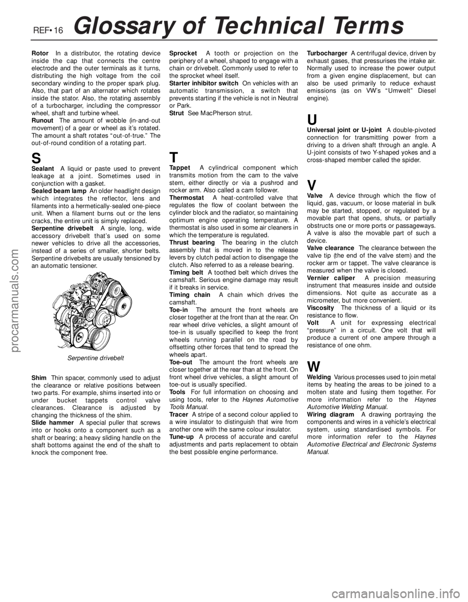
Serpentine drivebeltA single, long, wide
accessory drivebelt that’s used on some
newer vehicles to drive all the accessories,
instead of a series of smaller, shorter belts.
Serpentine drivebelts are usually tensioned by
an automatic tensioner.
ShimThin spacer, commonly used to adjust
the clearance or relative positions between
two parts. For example, shims inserted into or
under bucket tappets control valve
clearances. Clearance is adjusted by
changing the thickness of the shim.
Slide hammerA special puller that screws
into or hooks onto a component such as a
shaft or bearing; a heavy sliding handle on the
shaft bottoms against the end of the shaft to
knock the component free.SprocketA tooth or projection on the
periphery of a wheel, shaped to engage with a
chain or drivebelt. Commonly used to refer to
the sprocket wheel itself.
Starter inhibitor switchOn vehicles with an
automatic transmission, a switch that
prevents starting if the vehicle is not in Neutral
or Park.
StrutSee MacPherson strut.
TTappetA cylindrical component which
transmits motion from the cam to the valve
stem, either directly or via a pushrod and
rocker arm. Also called a cam follower.
ThermostatA heat-controlled valve that
regulates the flow of coolant between the
cylinder block and the radiator, so maintaining
optimum engine operating temperature. A
thermostat is also used in some air cleaners in
which the temperature is regulated.
Thrust bearingThe bearing in the clutch
assembly that is moved in to the release
levers by clutch pedal action to disengage the
clutch. Also referred to as a release bearing.
Timing beltA toothed belt which drives the
camshaft. Serious engine damage may result
if it breaks in service.
Timing chainA chain which drives the
camshaft.
Toe-inThe amount the front wheels are
closer together at the front than at the rear. On
rear wheel drive vehicles, a slight amount of
toe-in is usually specified to keep the front
wheels running parallel on the road by
offsetting other forces that tend to spread the
wheels apart.
Toe-outThe amount the front wheels are
closer together at the rear than at the front. On
front wheel drive vehicles, a slight amount of
toe-out is usually specified.
ToolsFor full information on choosing and
using tools, refer to the Haynes Automotive
Tools Manual.
TracerA stripe of a second colour applied to
a wire insulator to distinguish that wire from
another one with the same colour insulator.
Tune-upA process of accurate and careful
adjustments and parts replacement to obtain
the best possible engine performance.TurbochargerA centrifugal device, driven by
exhaust gases, that pressurises the intake air.
Normally used to increase the power output
from a given engine displacement, but can
also be used primarily to reduce exhaust
emissions (as on VW’s “Umwelt” Diesel
engine).
UUniversal joint or U-jointA double-pivoted
connection for transmitting power from a
driving to a driven shaft through an angle. A
U-joint consists of two Y-shaped yokes and a
cross-shaped member called the spider.
VValveA device through which the flow of
liquid, gas, vacuum, or loose material in bulk
may be started, stopped, or regulated by a
movable part that opens, shuts, or partially
obstructs one or more ports or passageways.
A valve is also the movable part of such a
device.
Valve clearanceThe clearance between the
valve tip (the end of the valve stem) and the
rocker arm or tappet. The valve clearance is
measured when the valve is closed.
Vernier caliperA precision measuring
instrument that measures inside and outside
dimensions. Not quite as accurate as a
micrometer, but more convenient.
ViscosityThe thickness of a liquid or its
resistance to flow.
VoltA unit for expressing electrical
“pressure” in a circuit. One volt that will
produce a current of one ampere through a
resistance of one ohm.
WWeldingVarious processes used to join metal
items by heating the areas to be joined to a
molten state and fusing them together. For
more information refer to the Haynes
Automotive Welding Manual.
Wiring diagramA drawing portraying the
components and wires in a vehicle’s electrical
system, using standardised symbols. For
more information refer to the Haynes
Automotive Electrical and Electronic Systems
Manual.
Serpentine drivebelt
procarmanuals.com