1993 DODGE TRUCK heating
[x] Cancel search: heatingPage 919 of 1502
14-100
FUEL
SYSTEM
•
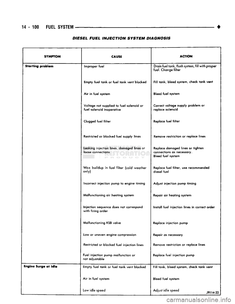
DIESEL
FUEL
INJECTION
SYSTEM DIAGNOSIS
SYMPTOM CAUSE
ACTION
Starting problem Improper
fuel
Drain
fuel
tank,
flush
system,
fill
with
proper
fuel.
Change
filter
Empty
fuel
tank
or
fuel
tank
vent
blocked
Fill
tank, bleed system, check
tank
vent
Air in
fuel
system Bleed
fuel
system
Voltage not supplied to
fuel
solenoid or
fuel
solenoid
inoperative
Correct voltage supply problem or
replace solenoid
Clogged
fuel
filter
Replace
fuel
filter
Restricted or blocked
fuel
supply lines Remove restriction or replace lines
Leaking
injection
lines, damaged lines or
loose
connections Replace damaged lines or tighten
connections as necessary. Bleed
fuel
system
Wax buildup in
fuel
filter
(cold
weather
only) Replace
fuel
filter,
use recommended
diesel
fuel
Incorrect
injection
pump to engine timing Adjust
injection
pump timing
Malfunctioning air heating system Repair air heating system
Injection
sequence does not correspond
with
firing
order Install
fuel
injection
lines in correct order
Malfunctioning
KSB
valve Replace
injection
pump
Low or uneven engine compression Repair as necessary
Restricted or blocked
fuel
injection
lines Remove restriction or replace lines
Fuel
injection
pump malfunction or not adjustable Replace
fuel
injection
pump
Engine
Surge at
idle
Empty
fuel
tank
or
fuel
tank
vent
blocked
Fill
tank, bleed system, check
tank
vent
Air in
fuel
system Bleed
fuel
system
Low
idle
speed Adjust
idle
speed
J9H4-22
Page 1087 of 1502
21 - 86
AUTOMATIC
TRANSMISSION-32RH/36RH/37RH/42RH/46RH
•
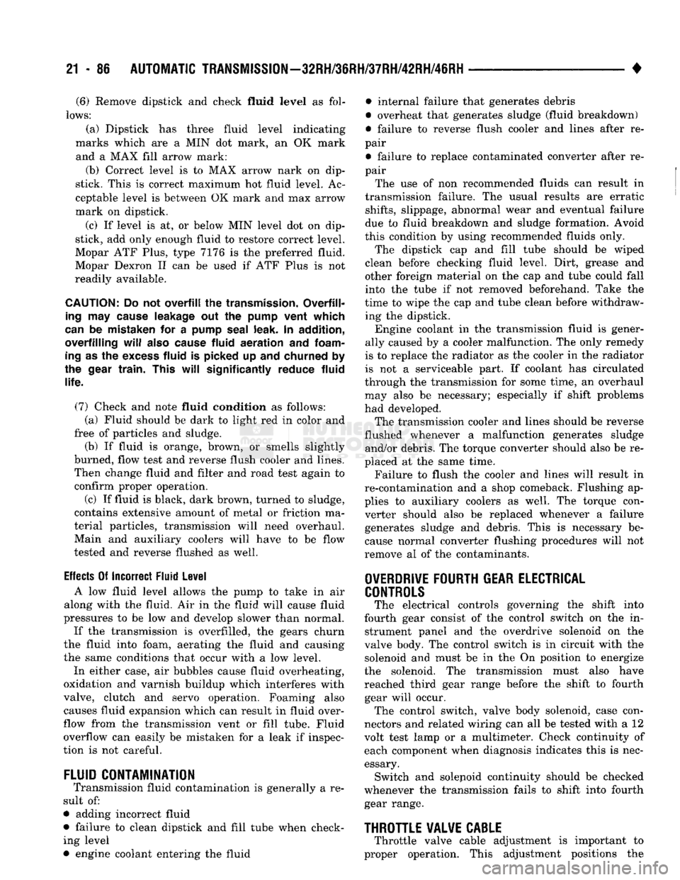
(6)
Remove dipstick and check fluid
level
as fol
lows:
(a) Dipstick has three fluid level indicating
marks which are a MIN dot mark, an OK mark and a MAX fill arrow mark:
(b) Correct level is to MAX arrow nark on dip
stick. This is correct maximum hot fluid level. Ac
ceptable level is between OK mark and max arrow
mark on dipstick.
(c) If level is at, or below MIN level dot on dip
stick, add only enough fluid to restore correct level.
Mopar ATF Plus, type 7176 is the preferred fluid.
Mopar Dexron II can be used if ATF Plus is not
readily available.
CAUTION:
Do not
overfill
the
transmission.
Overfill
ing
may
cause
leakage out the
pump
vent which
can
be mistaken for a
pump
seal
leak. In addition,
overfilling
will
also
cause
fluid
aeration
and
foam
ing
as the
excess
fluid is picked up and churned by
the
gear
train.
This
will
significantly
reduce fluid
life.
(7) Check and note fluid condition as follows: (a) Fluid should be dark to light red in color and
free of particles and sludge.
(b) If fluid is orange, brown, or smells slightly
burned, flow test and reverse flush cooler and lines. Then change fluid and filter and road test again to
confirm proper operation.
(c) If fluid is black, dark brown, turned to sludge,
contains extensive amount of metal or friction ma
terial particles, transmission will need overhaul. Main and auxiliary coolers will have to be flow
tested and reverse flushed as well.
Effects
Of Incorrect Fluid Level A low fluid level allows the pump to take in air
along with the fluid. Air in the fluid will cause fluid
pressures to be low and develop slower than normal.
If the transmission is overfilled, the gears churn
the fluid into foam, aerating the fluid and causing
the same conditions that occur with a low level.
In either case, air bubbles cause fluid overheating,
oxidation and varnish buildup which interferes with
valve, clutch and servo operation. Foaming also causes fluid expansion which can result in fluid over
flow from the transmission vent or fill tube. Fluid
overflow can easily be mistaken for a leak if inspec
tion is not careful.
FLUID
CONTAMINATION
Transmission fluid contamination is generally a re
sult of:
• adding incorrect fluid
• failure to clean dipstick and fill tube when check ing level
• engine coolant entering the fluid • internal failure that generates debris
• overheat that generates sludge (fluid breakdown)
• failure to reverse flush cooler and lines after re
pair
• failure to replace contaminated converter after re
pair
The use of non recommended fluids can result in
transmission failure. The usual results are erratic
shifts,
slippage, abnormal wear and eventual failure
due to fluid breakdown and sludge formation. Avoid
this condition by using recommended fluids only.
The dipstick cap and fill tube should be wiped
clean before checking fluid level. Dirt, grease and
other foreign material on the cap and tube could fall
into the tube if not removed beforehand. Take the
time to wipe the cap and tube clean before withdraw ing the dipstick.
Engine coolant in the transmission fluid is gener
ally caused by a cooler malfunction. The only remedy
is to replace the radiator as the cooler in the radiator
is not a serviceable part. If coolant has circulated
through the transmission for some time, an overhaul may also be necessary; especially if shift problems
had developed.
The transmission cooler and lines should be reverse
flushed whenever a malfunction generates sludge and/or debris. The torque converter should also be re
placed at the same time.
Failure to flush the cooler and lines will result in
re-contamination and a shop comeback. Flushing ap
plies to auxiliary coolers as well. The torque con verter should also be replaced whenever a failure
generates sludge and debris. This is necessary be
cause normal converter flushing procedures will not
remove al of the contaminants.
OVERDRIVE
FOURTH
GEAR
ELECTRICAL
CONTROLS
The electrical controls governing the shift into
fourth gear consist of the control switch on the in strument panel and the overdrive solenoid on the
valve body. The control switch is in circuit with the solenoid and must be in the On position to energize
the solenoid. The transmission must also have
reached third gear range before the shift to fourth gear will occur. The control switch, valve body solenoid, case con
nectors and related wiring can all be tested with a 12
volt test lamp or a multimeter. Check continuity of each component when diagnosis indicates this is nec
essary. Switch and solejioid continuity should be checked
whenever the transmission fails to shift into fourth
gear range.
THROTTLE
VALVE
CABLE
Throttle valve cable adjustment is important to
proper operation. This adjustment positions the
Page 1111 of 1502
21 - 110
AUTOMATIC TRANSMISSION-32RH/36RH/37RH/42RH/46RH
•
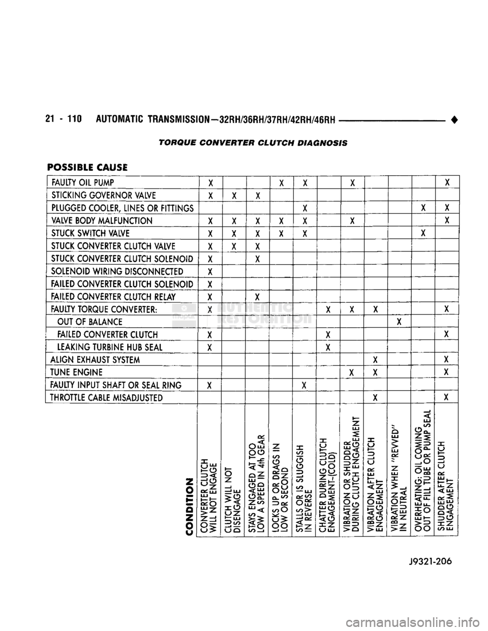
POSSIBLE CAUSE
FAULTY OIL PUMP X X X X X
STICKING GOVERNOR VALVE X X X
PLUGGED COOLER, LINES OR FITTINGS X X
X
VALVE BODY MALFUNCTION X X X X X X X
STUCK SWITCH VALVE X X X X X X
STUCK CONVERTER CLUTCH VALVE X X X
STUCK CONVERTER CLUTCH SOLENOID X X
SOLENOID WIRING DISCONNECTED X
FAILED CONVERTER CLUTCH SOLENOID X
FAILED CONVERTER CLUTCH RELAY X X
FAULTY TORQUE CONVERTER: X X X X X
OUT OF BALANCE X
FAILED CONVERTER CLUTCH X X X
LEAKING TURBINE HUB SEAL X X
ALIGN EXHAUST SYSTEM X X
TUNE ENGINE X X X
FAULTY INPUT SHAFT OR SEAL RING X X
THROTTLE CABLE MISADJUSTED X X
Z
0
o
z
o
CONVERTER CLUTCH
WILL
NOT
ENGAGE
CLUTCH WILL
NOT
DISENGAGE
STAYS
ENGAGED
AT
TOO
LOW
A
SPEED
IN
4th
GEAR
LOCKS UP
OR
DRAGS
IN
LOW
OR
SECOND
STALLS
OR IS
SLUGGISH
IN
REVERSE
CHATTER
DURING
CLUTCH
ENGAGEMENT-(COLD)
VIBRATION
OR
SHUDDER
DURING
CLUTCH
ENGAGEMENT
VIBRATION
AFTER
CLUTCH
ENGAGEMENT
VIBRATION
WHEN
"REVVED"
IN
NEUTRAL
OVERHEATING:
OIL
COMING
j
OUT
OF
FILL
TUBE
OR
PUMP
SEAL
SHUDDER
AFTER
CLUTCH
ENGAGEMENT
TORQUE CONVERTER CLUTCH DIAGNOSIS
Page 1146 of 1502
•
AUTOMATIC TRANSMISSION REMOVAL AND INSTALLATION
21 -
145
ITEM SET-TO-TORQUE
SPECIFICATION
(§)
203
N»m
(150
ft. lbs.)
(D
41
N*m
(30
ft. lbs.)
©
m
N«m
(50
ft. lbs.)
WITH
7"
RAIL
TRANSFER
CASE
Fig.
5
Transmission~To-Cross
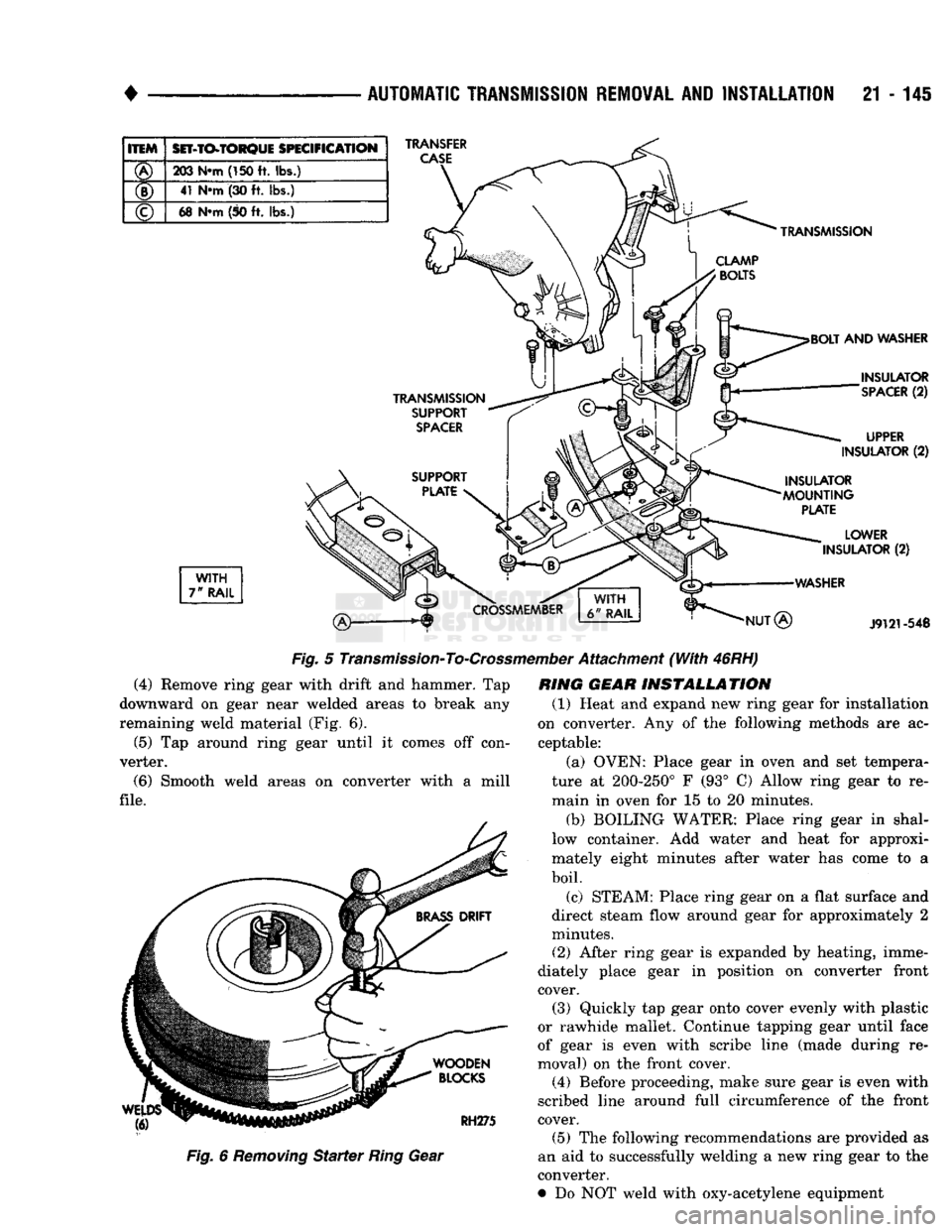
(4) Remove ring gear with drift
and
hammer.
Tap
downward
on
gear near welded areas
to
break
any
remaining weld material
(Fig. 6).
(5)
Tap
around ring gear until
it
comes
off
con
verter.
(6) Smooth weld areas
on
converter with
a
mill
file.
Fig.
6
Removing
Starter
Ring
Gear
mber
Attachment
(With
46RH)
RING GEAR INSTALLATION (1) Heat
and
expand
new
ring gear
for
installation
on converter.
Any of the
following methods
are ac
ceptable:
(a) OVEN: Place gear
in
oven
and set
tempera
ture
at
200-250°
F (93° C)
Allow ring gear
to re
main
in
oven
for 15 to 20
minutes.
(b)
BOILING WATER: Place ring gear
in
shal
low container.
Add
water
and
heat
for
approxi
mately eight minutes after water
has
come
to a
boil. (c) STEAM: Place ring gear
on a
flat surface
and
direct steam flow around gear
for
approximately
2
minutes.
(2) After ring gear
is
expanded
by
heating, imme
diately place gear
in
position
on
converter front cover. (3) Quickly
tap
gear onto cover evenly with plastic
or rawhide mallet. Continue tapping gear until face
of gear
is
even with scribe line (made during
re
moval)
on the
front cover.
(4) Before proceeding, make sure gear
is
even with
scribed line around full circumference
of the
front cover.
(5)
The
following recommendations
are
provided
as
an
aid to
successfully welding
a new
ring gear
to the
converter.
•
Do NOT
weld with oxy-acetylene equipment
Page 1344 of 1502
•
NP205 TRANSFER
CASE
21 - 343 Leakage from other sources (engine, transmission,
etc.) can be blown back onto the transfer case by air
flow under the vehicle. A blocked transfer case vent
can also cause leakage at the shaft seals due to in
ternal pressure build up.
Overfilling the transfer case can force fluid out the
vent and be mistaken for a leak. Correct fluid level checking methods should prevent overfill problems.
Checking
Fluid Level The correct method of checking transfer case fluid
level requires that the vehicle be level.
If fluid level is checked with the vehicle parked on
the shop floor, be sure the floor area used is level. If a hoist is used, a drive-on, or swivel arm type is pre
ferred.
Allow the transfer case fluid to settle for a minute
or so before checking. Correct fluid level is to the
bottom edge of the fill plug hole.
HARD SHIFTING
Hard shifting is generally caused by:
• misadjusted or binding linkage
• loose linkage or driveline components
• torque loads caused by 4WD operation on hard
paved surfaces • improper shifting techniques
• lack of lubricant which caused internal wear and
damage.
Loose linkage or driveline components are a result
of improperly tightened, stripped, or missing fasten
ers.
Remember that loose crossmember and mounting
parts can also generate a hard shift condition.
Torque loads in the transfer case can cause hard
shifting or even prevent shifting. Such loads are gen
erally a product of extensive operation on hard,
paved surfaces in 4WD range, unequal size tires, or
by mismatched front/rear axle gear ratios.
Linkage adjustment should be performed as de
scribed in the service section. Improper shift and op
erating techniques can be corrected by instructing
the driver. Internal component damage will require
overhaul to correct.
Failure to lubricate the shift linkage at recom
mended intervals will cause the linkage to bind. If
bind is severe enough to cause hard shifting, the linkage will have to be removed in order to correct
the condition. The linkage can be soaked in auto
matic transmission fluid if necessary. The fluid will
break up accumulated rust and corrosion.
NOISE
Some transfer case operating noise is normal. The
rotating gear train can produce sounds that may be
come audible at higher speeds and loads. However,
unusual noise is an indicator that internal compo nents may be worn or damaged. Low lubricant levels are a frequent cause of noisy
operation. Insufficient lubricant will lead to over
heating, subsequent damage to bearing and gear sur
faces and hard shifting.
Transfer case bearing noise is higher in pitch than
gear noise. If the unit is noisy in 4WD range only,
the front shaft bearings are probably at fault. If the unit is noisy in all ranges, an overhaul will be nec
essary to locate the faulty bearing.
Gear noise is lower in pitch and usually most no
ticeable when engaged and under load. Gear noise in
4WD drive range only is an indicator that the front shaft gears are damaged. Noise in all ranges could be
the idler or drive gears. An overhaul will be neces sary to determine which is at fault.
Frequently, suspected transfer case noise may actu
ally originate from another driveline component. The
proximity of other driveline components can some
times make it difficult to pinpoint the noise source.
TRANSFER CASE OPERATIONAL CHECK
The transfer case should not be removed until di
agnosis indicates the unit has actually malfunc
tioned. If a transfer case problem is suspected, check and verify operation before attempting repair. A
transfer case operational check may reveal that a
problem is actually related to another driveline com ponent.
(1) Raise vehicle on a hoist that will allow all four
wheels to rotate. (2) Check lubricant level. If lubricant level is low,
check for leaks at the bearing and seal retainers,
yokes,
drain/fill plugs, PTO cover and vent. (3) If vehicle is equipped with locking hubs, en
gage hubs. (4) Start engine, shift transmission into gear and
operate transfer case in all ranges. Observe propeller shaft action, shift efforts and operational sound lev
els as follows: (a) Only the rear propeller shaft should rotate in
two-wheel drive. Both propeller shafts should both
rotate in four-wheel drive high and low ranges. (b) If the front propeller shaft did not rotate in
either four-wheel drive range, the transfer case shift components may be worn or damaged. Or, if
the front shaft did rotate but the front wheels did
not, check the front axle shift mechanism and the locking hubs (if equipped). (c) If both propeller shafts rotate in four-wheel
drive but the wheels on one axle did not rotate, the
problem is in the axle. (d) If neither propeller shaft rotates in any
range, the problem is in the transmission or trans fer case. To determine which component is at fault,
proceed to next step. (5) Determine if fault is with transfer case or
transmission as follows:
Page 1376 of 1502
•
WHEELS
AND
TIRES
22 - 7 move and install dual rear wheels only when the
proper wrench is available.
INSTALLATION
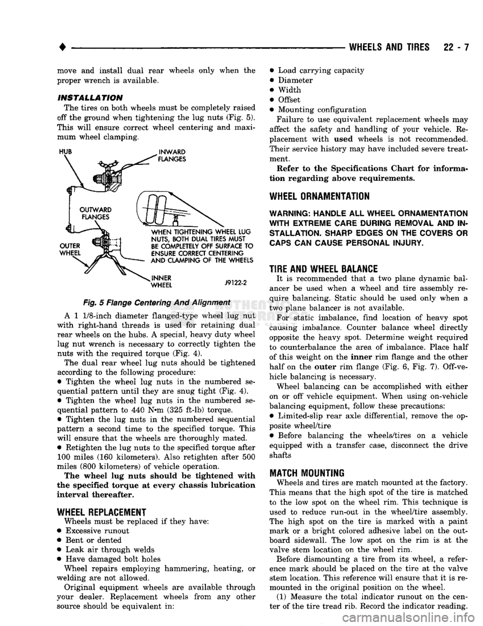
The tires on both wheels must be completely raised
off the ground when tightening the lug nuts (Fig. 5).
This will ensure correct wheel centering and maxi mum wheel clamping.
HUB
^
INWARD
Fig.
5 Flange Centering And
Alignment
A 1
1/8-inch
diameter flanged-type wheel lug nut
with right-hand threads is used for retaining dual rear wheels on the hubs. A special, heavy duty wheel lug nut wrench is necessary to correctly tighten the nuts with the required torque (Fig. 4).
The dual rear wheel lug nuts should be tightened
according to the following procedure:
• Tighten the wheel lug nuts in the numbered se
quential pattern until they are snug tight (Fig. 4).
• Tighten the wheel lug nuts in the numbered se
quential pattern to 440 N#m (325 ft-lb) torque.
• Tighten the lug nuts in the numbered sequential
pattern a second time to the specified torque. This will ensure that the wheels are thoroughly mated. • Retighten the lug nuts to the specified torque after 100 miles (160 kilometers). Also retighten after 500
miles (800 kilometers) of vehicle operation.
The wheel lug nuts should be tightened with
the specified torque at every chassis lubrication
interval thereafter.
WHEEL REPLACEMENT
Wheels must be replaced if they have:
• Excessive runout
• Bent or dented
• Leak air through welds
• Have damaged bolt holes Wheel repairs employing hammering, heating, or
welding are not allowed. Original equipment wheels are available through
your dealer. Replacement wheels from any other source should be equivalent in: • Load carrying capacity
• Diameter
® Width
• Offset
• Mounting configuration
Failure to use equivalent replacement wheels may
affect the safety and handling of your vehicle. Re
placement with used wheels is not recommended.
Their service history may have included severe treat ment.
Refer to the Specifications Chart for informa
tion regarding above requirements.
WHEEL ORNAMENTATION
WARNING; HANDLE
ALL
WHEEL ORNAMENTATION
WITH
EXTREME CARE DURING REMOVAL
AND IN
STALLATION. SHARP EDGES
ON THE
COVERS
OR
CAPS
CAN
CAUSE PERSONAL INJURY.
TIRE AND WHEEL BALANCE
It is recommended that a two plane dynamic bal
ancer be used when a wheel and tire assembly re
quire balancing. Static should be used only when a
two plane balancer is not available. For static imbalance, find location of heavy spot
causing imbalance. Counter balance wheel directly
opposite the heavy spot. Determine weight required
to counterbalance the area of imbalance. Place half of this weight on the inner rim flange and the other
half on the outer rim flange (Fig. 6, Fig. 7). Off-ve
hicle balancing is necessary. Wheel balancing can be accomplished with either
on or off vehicle equipment. When using on-vehicle
balancing equipment, follow these precautions: • Limited-slip rear axle differential, remove the op
posite wheel/tire • Before balancing the wheels/tires on a vehicle
equipped with a transfer case, disconnect the drive shafts
MATCH
MOUNTING
Wheels and tires are match mounted at the factory.
This means that the high spot of the tire is matched
to the low spot on the wheel rim. This technique is used to reduce run-out in the wheel/tire assembly.
The high spot on the tire is marked with a paint mark or a bright colored adhesive label on the out
board sidewall. The low spot on the rim is at the
valve stem location on the wheel rim. Before dismounting a tire from its wheel, a refer
ence mark should be placed on the tire at the valve stem location. This reference will ensure that it is re
mounted in the original position on the wheel. (1) Measure the total indicator runout on the cen
ter of the tire tread rib. Record the indicator reading.
Page 1438 of 1502
•
• —• •
HEATING
AND AIR
CONDITIONING
24 - 1 CONTENTS
page
CLIMATE CONTROL SYSTEM
............. 21
REFRIGERANT SYSTEM SERWICE
COMPRESSOR
SERWICE
(SD-709)
......... 21
PROCEDURES
.............
DIAGNOSTIC PROCEDURES
3
TORQUE SPECIFICATIONS
GENERAL INFORMATION
1
page
. 17
. 31
GENERAL INFORMATION
HEATER SYSTEM
All models use a Blend-Air type heater. Outside air
enters the heater through the cowl opening and
passes through a plenum chamber to the heater core. Air intake openings must be kept free of snow, ice and other obstructions for the heater system to pick
up sufficient outside air. A temperature control door
in the heater housing directs incoming air through
the heater core and/or the heater core bypass. The amount of blend (heated and non-heated air) is deter
mined by the setting of the temperature lever on the
instrument panel. Direction of the blended air is con
trolled by the HEAT-DEFROST lever on the instru ment panel. The blower switch and resistor block controls the
speed of the blower motor. This in turn controls the
velocity of the air flow from the heater outlets. The resistor block consists of 2 helical wound wire
resistors connected to terminals which are mechani cally attached to a glass-filled phenolic board. This
assembly is bolted to the plenum. The blower switch controls the blower motor speed
by selectively connecting the resistors in series to the
blower motor.
A self-adjusting clip, on each of 2 control cables has
been incorporated to simplify cable adjustment. This clip snaps onto the control cable core wire and will slide along the wire under a specific load to provide
an automatic cable adjustment.
AIR
CONDITIONING
SYSTEM
Air intake openings must be kept free of snow, ice
and other obstructions for the air conditioning sys
tem to pick up sufficient outside air.
COMPONENTS
• COMPRESSOR-The seven piston SD-709 com
pressor is used on all vehicles. This compressor com
presses the low pressure refrigerant vapor into a high pressure, high temperature vapor. • CLUTCH PULLEY AND COIL-These are
mounted on the compressor, providing a convenient
way to drive it and disengage it in accordance to the cooling needs.
• CONDENSER-The condenser is located in front
of the radiator. Its function is to cool the hot, high
pressure refrigerant gas causing it to condense into
high pressure liquid refrigerant.
• FILTER-DRIER—The filter-drier is used to remove
any traces of moisture from the refrigerant system.
This component incorporates the sight glass and the
high pressure relief valve.
• SIGHT GLASS-The sight glass is provided as a
diagnostic tool to observe refrigerant flow and indi cate refrigerant level. It is located at the top of the
filter drier.
• HIGH -PRESSURE RELIEF VALVE-This is a safety device designed to open automatically if the
system pressure reaches a predetermined level. This
will prevent system component damage. • EXPANSION (H) VALVE-The expansion (H)
valve is used to meter refrigerant into the evaporator
in accordance with cooling requirements. • EVAPORATOR COIL-The evaporator coil is lo
cated in the A/C unit. Its function is to cool and de-
humidify the air before it enters the vehicle. • FREEZE CONTROL-The main function of freeze
control is to prevent water on the evaporator coil face
from freezing which restricts the airflow. An elec
tronic temperature cycling switch is located on the
refrigerant plumbing (suction line) near the H-Valve.
The switch turns the compressor ON-OFF depending
on the temperature in the suction line. The switch is a sealed, specially calibrated unit. If found defective,
the switch must be replaced. • REFRIGERANT LINES-These lines are needed
to carry the refrigerant between the various system components.
• CONDENSATE DRAIN TUBE-Condensation
which accumulates on the bottom of the evaporator
HEATING
AND AIR
CONDITIONING
Page 1439 of 1502
24 - 2
HEATING
AND AIR
CONDITIONING
• housing is expelled through the molded rubber drain
tube into the engine compartment. The tube must be
kept open to prevent condensation from collecting in
the bottom of the housing.
The squeezed rubber flap at the drain tube tip is
designed to keep engine compartment air from enter ing into the system yet allow condensation to drain.
If the tip is not properly formed or has been dam
aged, the system will not drain properly. Therefore,
if the tube is damaged, it should be replaced.
• SERVICE VALVES—The service valves at the
compressor suction line and discharge tube are used
to test and service the refrigerant system. A special adapter (Tool C-4803) is required for performance
testing.
OPERATION The compressor increases the pressure and temper
ature of the refrigerant. The heated refrigerant vapor
is then pumped into the condenser where it cools by
giving off heat to air passing over the condenser fins.
As the refrigerant cools in the condenser, it con
denses into a liquid. Still under high pressure, the
liquid refrigerant passes into the receiver. The re
ceiver acts as a reservoir to furnish refrigerant to the
expansion (H) valve at all times. From the receiver,
the high pressure liquid refrigerant passes to the ex pansion (H) valve. The expansion (H) valve meters
refrigerant into the evaporator where a low pressure
is maintained by the suction side of the compressor.
As it enters the evaporator, the refrigerant immedi ately begins to boil by absorbing heat from the air
passing over the evaporator core. Having given up its
heat to boil the refrigerant, the air is cooled and
passes into the passenger compartment of the vehi
cle.
From the evaporator the vaporized refrigerant is
drawn back to the compressor to repeat the cycle. RADIATOR CAP
Air conditioned vehicles must be equipped with a
radiator cap having a holding pressure of 98-122 kPag (14-18 psig). Replace the radiator cap that does
not test within this specification.
CONDENSER Inspect the condenser for obstruction or foreign
matter. Clean if present.
Any obstruction to the free flow of air across the
condenser will decrease heat dissipation from the
condenser. This will in turn decrease the efficiency of
the condenser and decrease the evaporator's effi
ciency. These conditions result in increasing the dis
charge pressure and horsepower load on the engine.
The use of a bug screen is not recommended, it also
will decrease the free flow of air.
Inspect the condenser for bent or damaged fins.
The bent fins on the condenser deflect air flow and
decrease the condenser area.
BUG SCREENS Bug screens should NOT be installed on vehicles
equipped with air conditioning. A bug screen in
stalled in front of the condenser will reduce air flow
and air conditioner performance. Under severe heat
conditions a bug screen may cause the engine to
over-heat.
RESISTOR
BLOCK
The blower motor switch and resistor block, con
trols the speed of the blower motor. The resistor
block consists of 3 helical-wound wire resistors, con nected to terminals which are mechanically attached
to a phenolic board. This assembly is bolted to the
plenum.
The blower switch controls the blower motor speed
by selectively connecting in series one, two, three or none of the resistors to the blower motor.