1993 DODGE TRUCK heating
[x] Cancel search: heatingPage 319 of 1502
7
- 48
COOLING
SYSTEM
•
ENGINE BLOCK HEATERS
GENERAL
INFORMATION
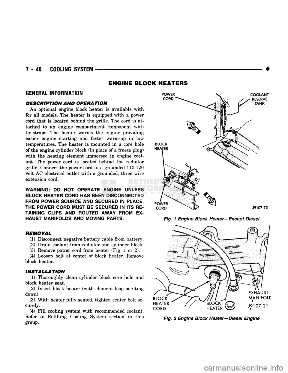
DESCRIPTION AND OPERATION An optional engine block heater
is
available with
for
all
models. The heater
is
equipped with
a
power
cord that
is
located behind the grille. The cord
is at
tached
to an
engine compartment component with
tie-straps.
The
heater warms
the
engine providing easier engine starting
and
faster warm-up
in low
temperatures. The heater
is
mounted
in a
core hole of the engine cylinder block (in place of
a
freeze plug)
with
the
heating element immersed
in
engine cool ant.
The
power cord
is
located behind
the
radiator
grille. Connect the power cord
to a
grounded 110-120
volt AC electrical outlet with
a
grounded, three wire
extension cord.
WARNING:
DO NOT
OPERATE ENGINE
UNLESS
BLOCK
HEATER
CORD
HAS
BEEN
DISCONNECTED
FROM POWER
SOURCE
AND
SECURED
IN
PLACE.
THE POWER
CORD
MUST BE
SECURED
IN ITS RE
TAINING
CLIPS
AND ROUTED AWAY FROM
EX
HAUST MANIFOLDS AND MOVING
PARTS.
REMOVAL
(1) Disconnect negative battery cable from battery.
(2) Drain coolant from radiator and cylinder block.
(3) Remove pow^r cord from heater (Fig.
1 or 2).
(4)
Loosen bolt
at
center
of
block heater. Remove
block heater.
INSTALLATION (1) Thoroughly clean cylinder block core hole
and
block heater seat. (2) Insert block heater (with element loop pointing
down).
(3) With heater fully seated, tighten center bolt se
curely.
(4)
Fill cooling system with recommended coolant.
Refer
to
Refilling Cooling System section
in
this
group.
Fig.
1
Engine
Block
Heater—Except
Diesel
Fig.
2
Engine
Block
Heater—Diesel
Engine
Page 367 of 1502
8D
- 16
IGNITION
SYSTEMS
• other operating conditions are causing engine over
heating. (The heat range rating refers to the operat
ing temperature of a particular type spark plug.
Spark plugs are designed to operate within specific
temperature ranges. This depends upon the thickness and length of the center electrodes porcelain insula
tor.)
GROUND
ELECTRODE
CENTER
ELECTRODE
DISSOLVED
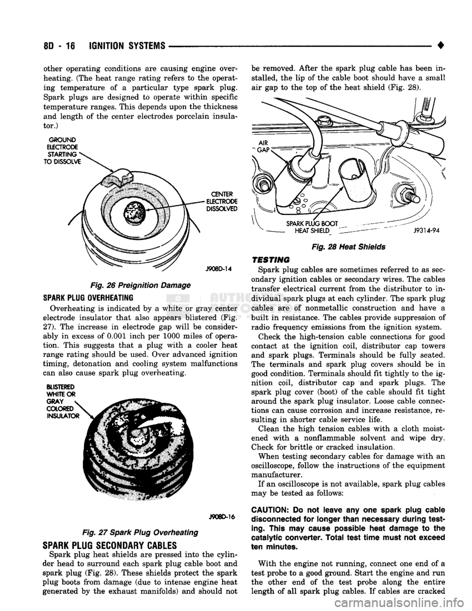
J908D-14 Fig. 26 Preignition Damage
SPARK
PLUG
OVERHEATING
Overheating is indicated by a white or gray center
electrode insulator that also appears blistered (Fig.
27).
The increase in electrode gap will be consider
ably in excess of 0.001 inch per 1000 miles of opera
tion. This suggests that a plug with a cooler heat
range rating should be used. Over advanced ignition
timing, detonation and cooling system malfunctions can also cause spark plug overheating.
BLISTERED
WHITE
OR
J908D-16
Fig. 27 Spark Plug Overheating
SPARK
PLUG
SECONDARY
CABLES
Spark plug heat shields are pressed into the cylin
der head to surround each spark plug cable boot and spark plug (Fig. 28). These shields protect the spark
plug boots from damage (due to intense engine heat
generated by the exhaust manifolds) and should not be removed. After the spark plug cable has been in
stalled, the lip of the cable boot should have a small
air gap to the top of the heat shield (Fig. 28).
Fig.
28 Heat
Shields
TESTING
Spark plug cables are sometimes referred to as sec
ondary ignition cables or secondary wires. The cables
transfer electrical current from the distributor to in dividual spark plugs at each cylinder. The spark plug
cables are of nonmetallic construction and have a
built in resistance. The cables provide suppression of radio frequency emissions from the ignition system.
Check the high-tension cable connections for good
contact at the ignition coil, distributor cap towers and spark plugs. Terminals should be fully seated.
The terminals and spark plug covers should be in good condition. Terminals should fit tightly to the ig
nition coil, distributor cap and spark plugs. The spark plug cover (boot) of the cable should fit tight
around the spark plug insulator. Loose cable connec
tions can cause corrosion and increase resistance, re sulting in shorter cable service life. Clean the high tension cables with a cloth moist
ened with a nonflammable solvent and wipe dry.
Check for brittle or cracked insulation. When testing secondary cables for damage with an
oscilloscope, follow the instructions of the equipment
manufacturer. If an oscilloscope is not available, spark plug cables
may be tested as follows:
CAUTION:
Do not leave any one
spark
plug
cable
disconnected
for
longer
than
necessary
during test
ing.
This
may
cause
possible
heat
damage
to the
catalytic converter. Total test
time
must
not exceed
ten
minutes.
With the engine not running, connect one end of a
test probe to a good ground. Start the engine and run the other end of the test probe along the entire length of all spark plug cables. If cables are cracked
Page 398 of 1502
INSTRUMENT
PANEL
AND
GAUGES
8E - 17
HEATER
A/C
CONTROL
REMOVAL
(1) Remove map lamp.
(2) Remove cluster bezel (refer to Cluster Bezel Re
moval).
(3) Remove 2 control attaching screws.
(4) Pull control rearward.
(5) Disconnect blower switch wiring.
(6) Disconnect wires to pushbutton switch (three
connectors). (7) Disconnect illumination lamp.
(8) Disconnect vacuum harness.
(9) Disconnect temperature cable.
(10) Remove control.
INSTALLATION
(1) Position control near panel.
(2) Connect temperature cable (see Group 24 -
Heating and Air Conditioning).
(3) Connect vacuum harness. (4) Connect illumination lamp.
(5) Attach 3 wire connectors to pushbutton switch.
(6) Connect wires to blower motor switch.
(7) Push control into panel.
(8) Install 2 control mounting screws.
(9) Install cluster bezel.
(10) Install map lamp.
INSTRUMENT
PANEL SWITCHES
HEADLAMP
SWITCH
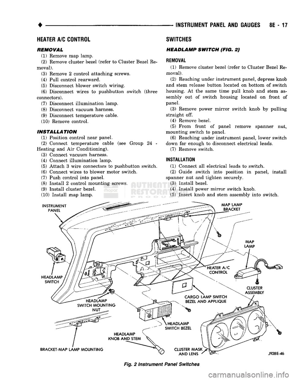
(FIG. 2)
REMOVAL
(1) Remove cluster bezel (refer to Cluster Bezel Re
moval).
(2) Reaching under instrument panel, depress knob
and stem release button located on bottom of switch
housing. At the same time pull knob and stem as sembly out of switch housing located on front of
panel.
(3) Remove power mirror switch knob by pulling
straight off.
(4) Remove bezel.
(5) From front of panel remove spanner nut,
mounting switch to panel. (6) Reaching under instrument panel, lower switch
down far enough to disconnect electrical leads. (7) Remove switch.
INSTALLATION
(1) Connect all electrical leads to switch.
(2) Guide switch into position in panel, install
spanner nut and tighten securely.
(3) Install bezel.
(4) Install power mirror switch knob.
(5) Insert knob and stem assembly into switch.
AAAP LAMP
BRACKET
HEADLAMP SWITCH
CLUSTER
ASSEMBLY
HEADLAMP
SWITCH MOUNTING NUT
CARGO
LAMP SWITCH
BEZEL
AND APPLIQUE
HEADLAMP
KNOB AND STEM
BRACKET-MAP LAMP MOUNTING HEADLAMP
SWITCH BEZEL
CLUSTER AAASK AND LENS
J928E-46
Fig.
2 Instrument
Panel
Switches
Page 625 of 1502
TRANSFER
CASE
INSULATOR
MOUNTING PLATE
NUT(B
RAIL
ASSEMBLY
SPACER
UPPER
INSULATOR
NUT®
LOWER
INSULATOR
J9109-242
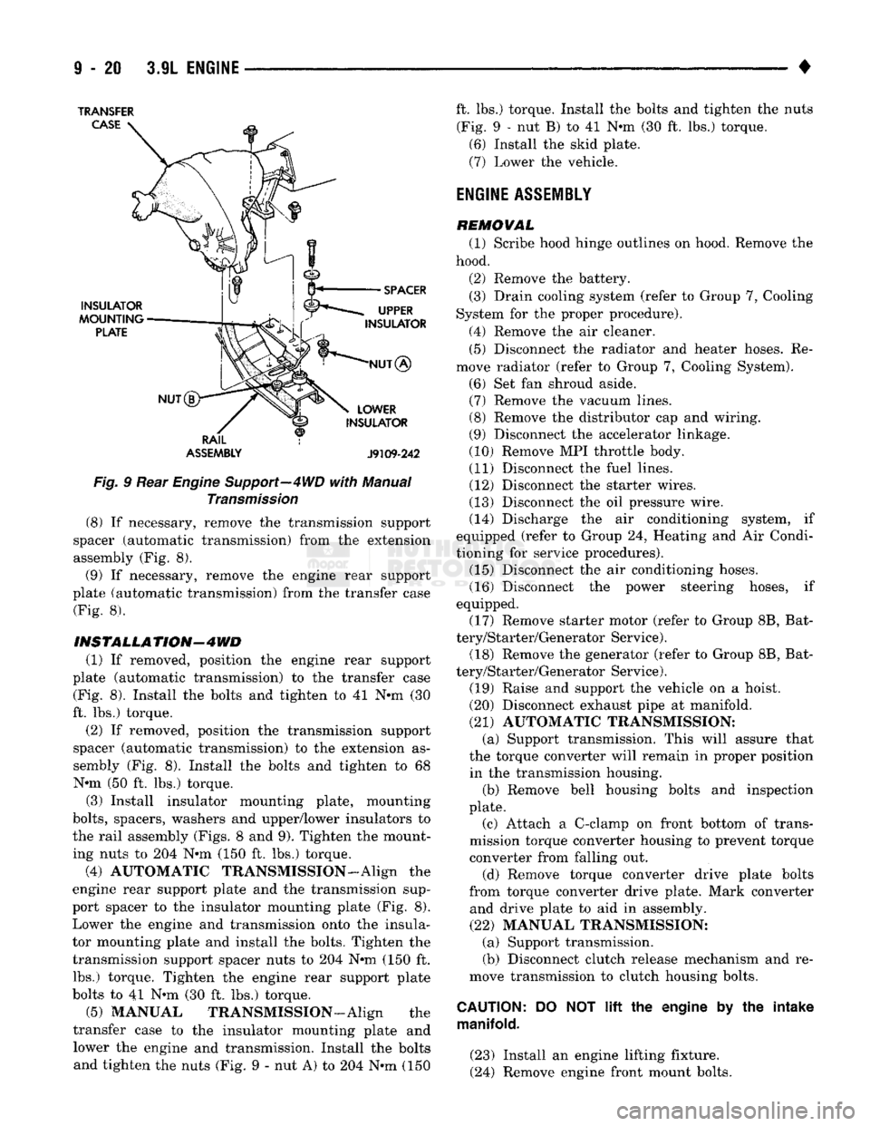
Fig.
9 Rear
Engine
Support—4WD
with
Manual
Transmission
(8) If necessary, remove the transmission support
spacer (automatic transmission) from the extension
assembly (Fig. 8).
(9) If necessary, remove the engine rear support
plate (automatic transmission) from the transfer case (Fig. 8).
INSTALLATION-4WD
(1) If removed, position the engine rear support
plate (automatic transmission) to the transfer case (Fig. 8). Install the bolts and tighten to 41 N-m (30
ft. lbs.) torque.
(2) If removed, position the transmission support
spacer (automatic transmission) to the extension as
sembly (Fig. 8). Install the bolts and tighten to 68 N-m (50 ft. lbs.) torque.
(3) Install insulator mounting plate, mounting
bolts,
spacers, washers and upper/lower insulators to
the rail assembly (Figs. 8 and 9). Tighten the mount
ing nuts to 204 N*m (150 ft. lbs.) torque.
(4) AUTOMATIC TRANSMISSION-Align the
engine rear support plate and the transmission sup
port spacer to the insulator mounting plate (Fig. 8). Lower the engine and transmission onto the insula
tor mounting plate and install the bolts. Tighten the transmission support spacer nuts to 204 N-m (150 ft. lbs.) torque. Tighten the engine rear support plate
bolts to 41 N-m (30 ft. lbs.) torque.
(5) MANUAL TRANSMISSION—Align the
transfer case to the insulator mounting plate and lower the engine and transmission. Install the bolts and tighten the nuts (Fig. 9 - nut A) to 204 N-m (150 ft. lbs.) torque. Install the bolts and tighten the nuts
(Fig. 9 - nut B) to 41 N-m (30 ft. lbs.) torque. (6) Install the skid plate.
(7) Lower the vehicle.
ENGINE
ASSEMBLY
REMOVAL (1) Scribe hood hinge outlines on hood. Remove the
hood.
(2) Remove the battery. (3) Drain cooling system (refer to Group 7, Cooling
System for the proper procedure).
(4) Remove the air cleaner. (5) Disconnect the radiator and heater hoses. Re
move radiator (refer to Group 7, Cooling System).
(6) Set fan shroud aside. (7) Remove the vacuum lines. (8) Remove the distributor cap and wiring.
(9) Disconnect the accelerator linkage.
(10) Remove MPI throttle body. (11) Disconnect the fuel lines. (12) Disconnect the starter wires.
(13) Disconnect the oil pressure wire. (14) Discharge the air conditioning system, if
equipped (refer to Group 24, Heating and Air Condi
tioning for service procedures). (15) Disconnect the air conditioning hoses.
(16) Disconnect the power steering hoses, if
equipped. (17) Remove starter motor (refer to Group 8B, Bat
tery/Starter/Generator Service). (18) Remove the generator (refer to Group 8B, Bat
tery/Starter/Generator Service).
(19) Raise and support the vehicle on a hoist.
(20) Disconnect exhaust pipe at manifold.
(21) AUTOMATIC TRANSMISSION: (a) Support transmission. This will assure that
the torque converter will remain in proper position in the transmission housing. (b) Remove bell housing bolts and inspection
plate.
(c) Attach a C-clamp on front bottom of trans
mission torque converter housing to prevent torque
converter from falling out.
(d) Remove torque converter drive plate bolts
from torque converter drive plate. Mark converter and drive plate to aid in assembly.
(22) MANUAL TRANSMISSION: (a) Support transmission.
(b) Disconnect clutch release mechanism and re
move transmission to clutch housing bolts.
CAUTION:
DO NOT
lift
the engine by the intake
manifold.
(23) Install an engine lifting fixture.
(24) Remove engine front mount bolts.
Page 655 of 1502
TRANSFER
CASE
TRANSFER
CASE
ENGINE
REAR
SUPPORT PLATE
EXTENSION
ASSEMBLY
TRANSMISSION
SUPPORT
SPACER
SPACER
UPPER
INSULATOR
INSULATOR
MOUNTING
PLATE
LOWER
INSULATOR
fT^RAIL
J9109-244
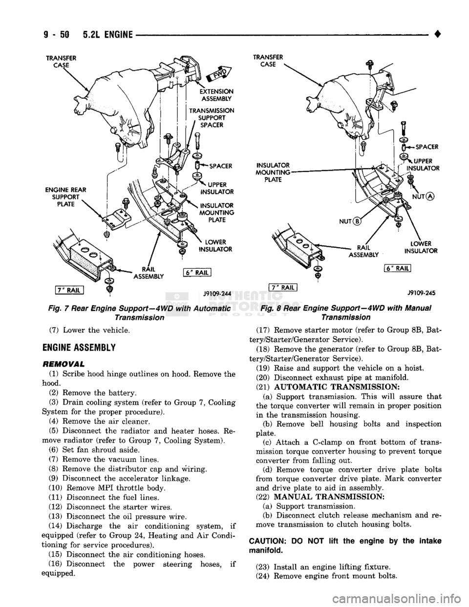
Fig,
7 Rear Engine Support—4WD
with
Automatic
Transmission
(7)
Lower the vehicle.
ENGINE
ASSEMBLY
REMOVAL
(1) Scribe hood hinge outlines on hood. Remove the
hood. (2) Remove the battery.
(3) Drain cooling system (refer to Group 7, Cooling
System for the proper procedure). (4) Remove the air cleaner.
(5) Disconnect the radiator and heater hoses. Re
move radiator (refer to Group 7, Cooling System). (6) Set fan shroud aside.
(7)
Remove the vacuum lines.
(8) Remove the distributor cap and wiring.
(9) Disconnect the accelerator linkage.
(10) Remove MPI throttle body.
(11) Disconnect the fuel lines.
(12) Disconnect the starter wires.
(13) Disconnect the oil pressure wire.
(14) Discharge the air conditioning system, if
equipped (refer to Group 24, Heating and Air Condi
tioning for service procedures).
(15) Disconnect the air conditioning hoses.
(16) Disconnect the power steering hoses, if
equipped.
INSULATOR
MOUNTING
PLATE
SPACER
UPPER
L\ f
INSULATOR
NUT®
RAIL
ASSEMBLY
LOWER
INSULATOR
l6ff
RAIL
I
J9109-245
Fig.
8 Rear
Engine
Support—4WD
with
Manual
Transmission
(17) Remove starter motor (refer to Group 8B, Bat
tery/Starter/Generator Service).
(18) Remove the generator (refer to Group 8B, Bat
tery/Starter/Generator Service).
(19) Raise and support the vehicle on a hoist.
(20) Disconnect exhaust pipe at manifold.
(21)
AUTOMATIC TRANSMISSION: (a) Support transmission. This will assure that
the torque converter will remain in proper position in the transmission housing. (b) Remove bell housing bolts and inspection
plate. (c) Attach a C-clamp on front bottom of trans
mission torque converter housing to prevent torque
converter from falling out. (d) Remove torque converter drive plate bolts
from torque converter drive plate. Mark converter and drive plate to aid in assembly.
(22)
MANUAL TRANSMISSION; (a) Support transmission.
(b) Disconnect clutch release mechanism and re
move transmission to clutch housing bolts.
CAUTION:
manifold.
DO
NOT lift the
engine
by the
intake
(23) Install an engine lifting fixture.
(24) Remove engine front mount bolts.
Page 685 of 1502
9
- 80 5.9L
ENGINE
•
TRANSFER
CASE
TRANSFER
CASE
ENGINE REAR
SUPPORT
PLATE
INSULATOR
MOUNTING
PLATE
LOWER
INSULATOR
\7"
RAIL
1
J9109-244
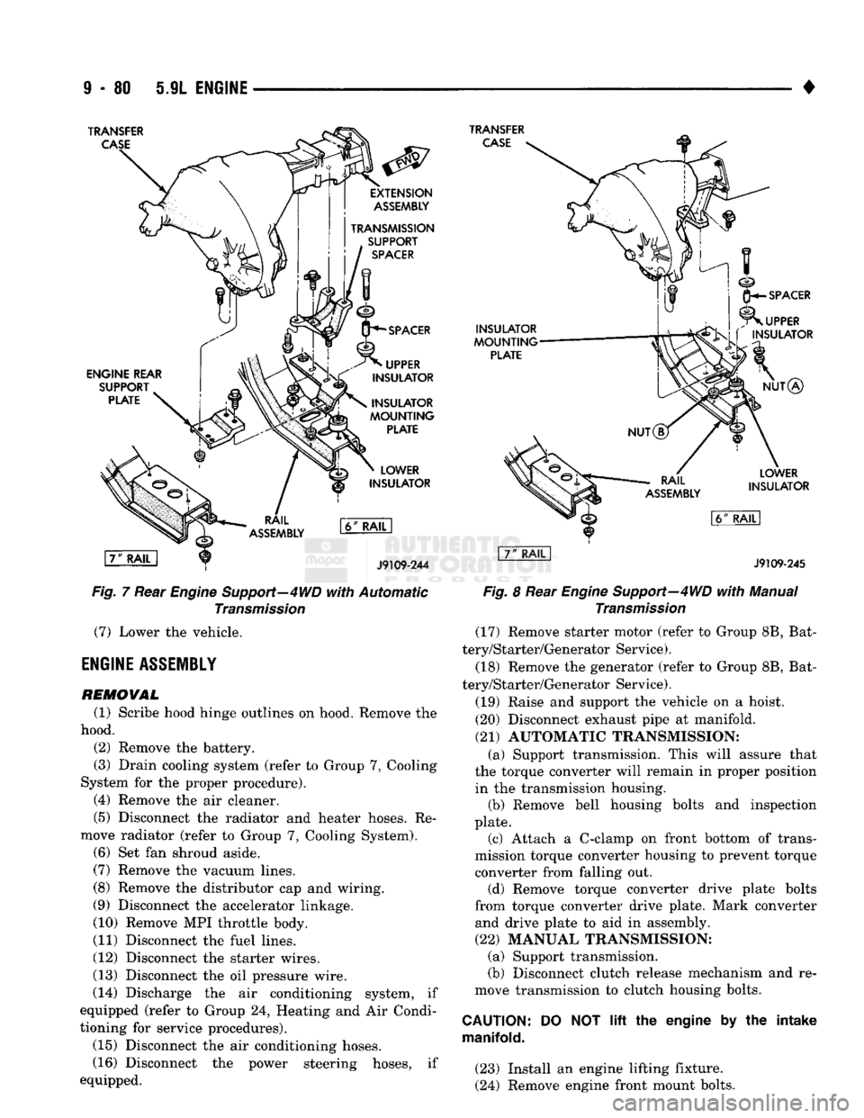
Fig.
7 Rear
Engine
Support—4WD
with
Automatic
Transmission
(7) Lower the vehicle.
ENGINE
ASSEMBLY
REMOVAL
(1) Scribe hood hinge outlines on hood. Remove the
hood. (2) Remove the battery.
(3) Drain cooling system (refer to Group 7, Cooling
System for the proper procedure). (4) Remove the air cleaner.
(5) Disconnect the radiator and heater hoses. Re
move radiator (refer to Group 7, Cooling System). (6) Set fan shroud aside.
(7) Remove the vacuum lines.
(8) Remove the distributor cap and wiring.
(9) Disconnect the accelerator linkage.
(10) Remove MPI throttle body.
(11) Disconnect the fuel lines.
(12) Disconnect the starter wires.
(13) Disconnect the oil pressure wire.
(14) Discharge the air conditioning system, if
equipped (refer to Group 24, Heating and Air Condi
tioning for service procedures).
(15) Disconnect the air conditioning hoses.
(16) Disconnect the power steering hoses, if
equipped.
INSULATOR
MOUNTING
PLATE
SPACER
UPPER
INSULATOR
NUT®
LOWER
INSULATOR
J9109-245
Fig.
8 Rear
Engine
Support—4WD
with
Manual
Transmission
(17) Remove starter motor (refer to Group 8B, Bat
tery/Starter/Generator Service).
(18) Remove the generator (refer to Group 8B, Bat
tery/Starter/Generator Service).
(19) Raise and support the vehicle on a hoist.
(20) Disconnect exhaust pipe at manifold.
(21) AUTOMATIC TRANSMISSION: (a) Support transmission. This will assure that
the torque converter will remain in proper position in the transmission housing. (b) Remove bell housing bolts and inspection
plate. (c) Attach a C-clamp on front bottom of trans
mission torque converter housing to prevent torque converter from falling out. (d) Remove torque converter drive plate bolts
from torque converter drive plate. Mark converter and drive plate to aid in assembly.
(22) MANUAL TRANSMISSION; (a) Support transmission.
(b) Disconnect clutch release mechanism and re
move transmission to clutch housing bolts.
CAUTION:
manifold.
DO
NOT
lift
the engine by the intake
(23) Install an engine lifting fixture.
(24) Remove engine front mount bolts.
Page 739 of 1502
9
- 134 5.9L
(DIESEL) ENGINE
• (4) Fill the engine with oil. Run the engine and
check for leaks.
(5) Stop the engine and check the oil level with the
dipstick.
CUP
PLUG
J9109-30
Fig.
17 Cup Plug Locations in Cylinder Block INSTALLATION
(1) Install the cylinder head onto the block.
(2) Install the engine assembly into the vehicle.
PISTON
/
CONNECTING ROD ASSEMBLY
The turbocharged intercooler piston has a Ni-Resist
insert with a keystone profile for the top compression
ring. The new piston has a new design bowl and a 7 mm longer piston pin. These pistons can not be in
terchanged with earlier models.
REMOVAL (1) Remove the engine assembly from the vehicle.
(2) Remove the cylinder head from the block.
(3) Remove the oil pan and suction pump.
(4) If the cylinder bores have ridges, use a ridge
reamer to cut the ridge from the top of the cylinder
bore before removing the piston. Make sure the ridge reamer does not make a deep cut into the bore. DO
NOT remove more metal than is necessary to remove
the ridge.
(5) If cylinders have ridges, the cylinders are over
size and will need boring. (6) Use a hammer and a steel stamp to mark the
cylinder number onto each connecting rod cap. Mark
the cylinder number onto the top of each piston. (7) Remove the connecting rod bolts and rod caps.
Use care so the cylinder bores and connecting rods
are not damaged. (8) Use a hammer handle or similar object to push
the piston and connecting rod through the cylinder
bore.
(9) Store the piston/rod assemblies in a rack.
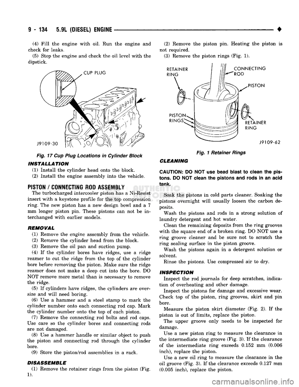
DISASSEMBLE (1) Remove the retainer rings from the piston (Fig.
1).
(2) Remove the piston pin. Heating the piston is
not required. (3) Remove the piston rings (Fig. 1). RETAINER
RING
CONNECTING
ROD
PISTON
PISTON RIN RETAINER
RING J9109-62
Fig.
1 Retainer
Rings
CLEANING
CAUTION: DO NOT use bead
blast
to clean the
pis
tons.
DO
NOT
clean the pistons and rods in an acid
tank.
Soak the pistons in cold parts cleaner. Soaking the
pistons overnight will usually loosen the carbon de posits.
Wash the pistons and rods in a strong solution of
laundry detergent and hot water.
Clean the remaining deposits from the ring grooves
with the square end of a broken ring. DO NOT use a
ring groove cleaner and be sure not to scratch the
ring sealing surface in the piston groove.
Wash the pistons again in a detergent solution or
solvent.
Rinse the pistons. Use compressed air to dry.
INSPECTION Inspect the rod journals for deep scratches, indica
tion of overheating and other damage.
Inspect the pistons for damage and excessive wear.
Check top of the piston, ring grooves, skirt and pin
bore.
Measure the piston skirt diameter (Fig. 2). If the
piston is out of limits, replace the piston.
The upper groove only needs to be inspected for
damage.
Use a new piston ring to measure the clearance in
the intermediate ring groove (Fig. 3). If the clearance of the intermediate ring exceeds 0.152 mm (0.006
inch),
replace the piston.
Use a new oil ring to measure the clearance in the
oil groove (Fig. 3). If the clearance exceeds 0.127 mm (0.005 inch), replace the piston.
Page 744 of 1502
•
5.9L
(DIESEL) ENGINE 9 - 139
Fig.
2 Main Beating Cap
Removal
CAUTION:
Crankshaft must be
lifted
straight
off the
bearings
to
prevent
damage
to the
thrust
bearings.
Fig.
3 Lifting Crankshaft out of Cylinder
Block
(7)
Remove the main bearings from the block and
the main caps. (8) Remove the piston cooling nozzles by using a
3/16 inch pin punch to push them out (Fig. 4).
Fig.
4
Piston
Cooling
Nozzles
CLEANING
AND
INSPECTION
Clean the crankshaft oil galley holes with a nylon
brush. Rinse in clean solvent and dry with compressed air. Inspect the front and rear seal contact areas of the
crankshaft for scratches or grooving. The service seal kit will position the seal slightly
deeper into the seal bore so it will contact the crank
shaft at a different location. If this has already been
done and the crankshaft has two worn areas, install
a wear sleeve to provide a new contact surface for
the seal.
Inspect the rod and main journal for deep scores,
signs of overheating and other abnormal marks.
CRANKSHAFT
REWORK
Crankshaft main and rod journals may be ground
in increments of 0.25 mm (0.0098 inch) up to a total
of 1.00 mm (0.0394 inch). The only exception is the main journal thrust
width surface. This journal must be ground in incre ments of 0.50 mm (0.0197 inch) up to a total of 1.00
mm (0.0394 inch). The thrust surface is located on
the No.6 main bearing. When the thrust surface re quires grinding, the main journal must be ground to
the same undersize dimension.
MAIN
JOURNAL
All main journals are to be ground in the opposite
direction of engine rotation (clockwise as viewed
from the front of crankshaft). Polish the journals in
the same direction as engine rotation.
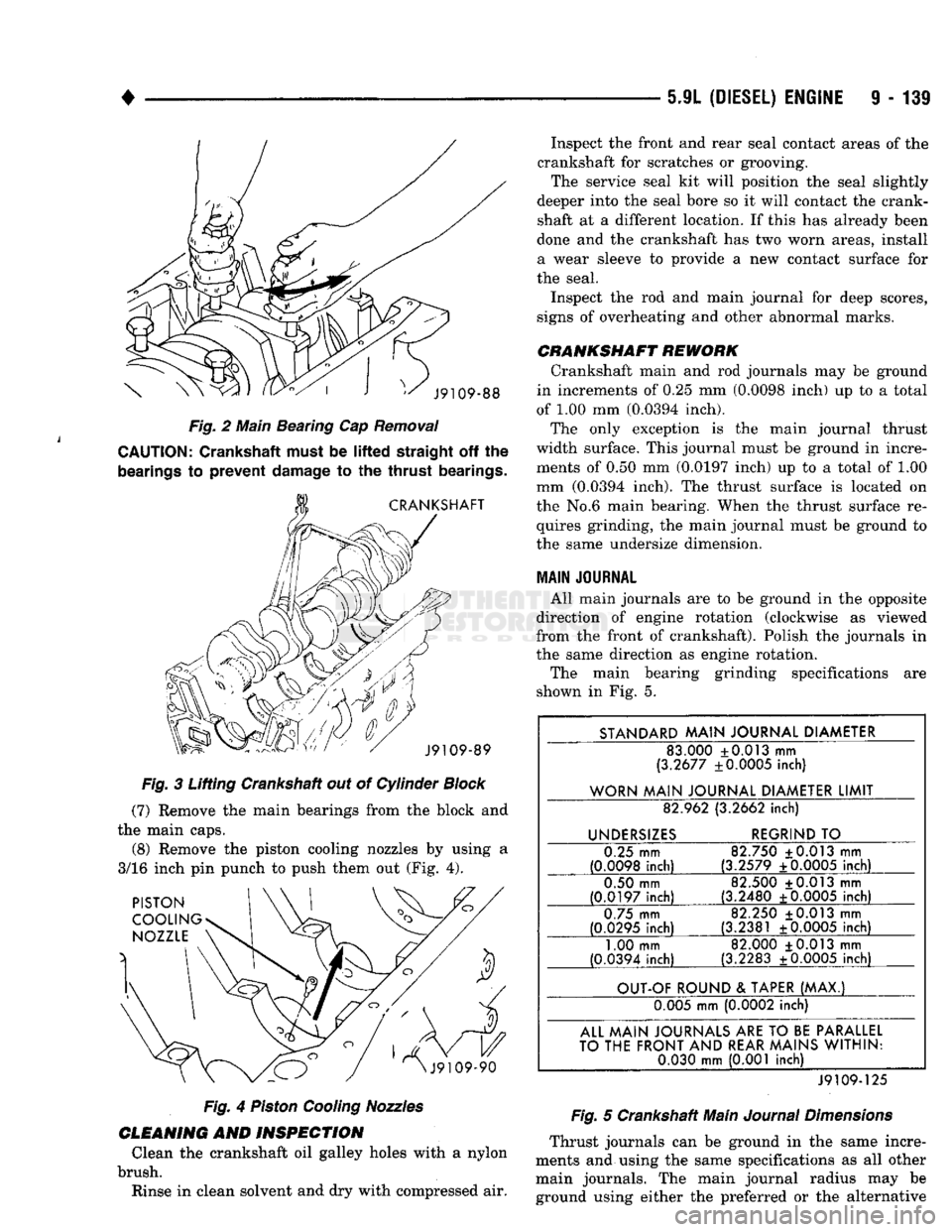
The main bearing grinding specifications are
shown in Fig. 5.
STANDARD
MAIN
JOURNAL
DIAMETER
83.000 +0.013 mm
(3.2677 ±0.0005 inch)
WORN
MAIN
JOURNAL
DIAMETER
LIMIT
82.962 (3.2662
inch)
UNDERSIZES
REGRIND
TO
0.25 mm
(0.0098
inch)
82.750 ±0.013 mm
(3.2579 ±0.0005
inch)
0.50 mm
(0.0197
inch)
82.500 +0.013 mm
(3.2480 +0.0005
inch)
0.75 mm
(0.0295
inch)
82.250 +0.013 mm
(3.2381 ±0.0005
inch)
1.00 mm
(0.0394 inch) 82.000 +0.013 mm
(3.2283 ±0.0005 inch)
OUT-OF
ROUND
&
TAPER
(MAX.)
0.005 mm (0.0002 inch)
ALL
MAIN
JOURNALS
ARE
TO
BE
PARALLEL
TO
THE
FRONT
AND
REAR
MAINS
WITHIN:
0.030
mm
(0.001 inch)
J9109-125
Fig.
5 Crankshaft Main
Journal
Dimensions
Thrust journals can be ground in the same incre
ments and using the same specifications as all other main journals. The main journal radius may be ground using either the preferred or the alternative