1993 DODGE TRUCK heating
[x] Cancel search: heatingPage 1440 of 1502
•
HEATING
AND AIR
CONDITIONING
24 - 3
DIAGNOSTIC
PROCEDURES
INDEX
page
page ..
7
General Information
3
.
. 3
Heating System Output
3
Air
Conditioning System
Blower
Motor
GENERAL
INFORMATION
The reason for owner dissatisfaction must be thor
oughly understood before any attempt is made to re
pair or replace any parts. It must be determined if
the condition is the heater system, the refrigerant system, air conditioning air flow or related to the
compressor. After confirming the condition, a func
tional test is suggested using the diagnostic charts.
After the condition has been properly diagnosed and corrected, check out the complete system to assure
that it is performing satisfactorily. The following charts have been developed for quick
reference. If the step by step method used is not com pletely understood, refer to the correct section of the Service Manual for detailed explanations.
HEATING
SYSTEM
OUTPUT
WARNING:
IF
VEHICLE
HAS
BEEN
RUN
RECENTLY,
WAIT
15
MINUTES
BEFORE
REMOVING
CAP, THEN
PLACE
A RAG
OVER
THE CAP AND
TURN
IT TO
THE
FIRST
STOP.
ALLOW
PRESSURE
TO
ESCAPE
THROUGH
THE
OVERFLOW
TUBE
AND
WHEN
THE
SYSTEM
STABILIZES,
REMOVE
THE CAP
COM
PLETELY.
Check the radiator coolant level, drive belt tension,
engine vacuum line connections, radiator air flow and radiator fan operation. Start engine and bring to
normal operating temperature (refer to Group 7,
Cooling System).
Engine coolant is provided to the heater system by
2 heater hoses. With engine idling at normal operat
ing temperature, set the heater control to maximum
heat, defrost and high blower setting. Using a test
thermometer, check the air temperature coming from
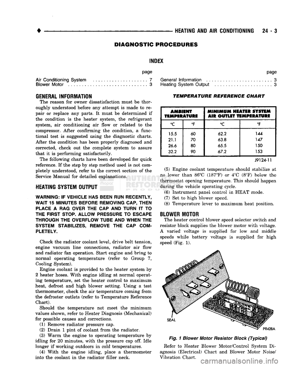
the defroster outlets (refer to Temperature Reference Chart).
Should the temperature not meet the minimum
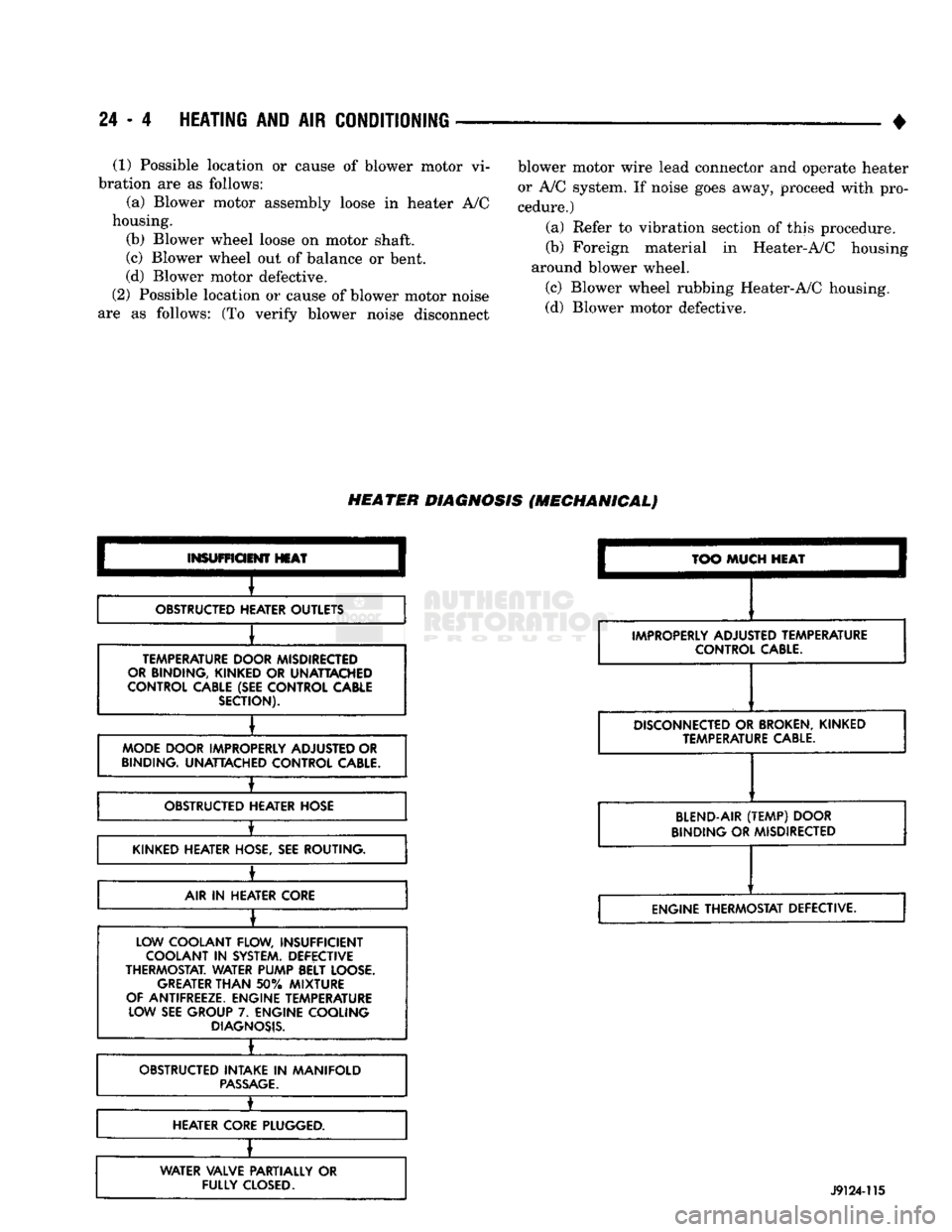
values shown, refer to Heater Diagnosis (Mechanical)
for possible causes and corrections.
(1) Remove radiator pressure cap.
(2) Drain 1 pint of coolant from the radiator.
(3) Warm the engine to operating temperature by
idling for 20 minutes, with the pressure cap off. Idle longer if working outdoors in cold temperatures. (4) With the engine idling, place a thermometer
into the coolant in the radiator filler neck.
TEMPERATURE REFERENCE CHART
AMBIENT
MINIMUM
HEATER SYSTEM
TEMPERATURE
AIR OUTLET
TEMPERATURE
°C
°F
°C
°F
15.5 60 62.2 144
21.1 70
63.8 147
26.6 80
65.5 150
32.2 90 67.2 153
J9124-11
(5) Engine coolant temperature should stabilize at
no lower than 86°C (187°F) or 4°C (8°F) below the
thermostat opening temperature. This should happen during the vehicle operating cycle.
(6) Instrument panel control in HEAT mode.
(7) Set to high blower speed.
(8) Temperature lever to maximum heat position.
BLOWER
MOTOR
The heater control blower speed selector switch and
resistor block supplies the blower motor with voltage.
A varied voltage is supplied for low and middle speeds while battery voltage is supplied for high
speed (Fig. 1).
Fig.
1
Blower
Motor
Resistor
Block
(Typical)
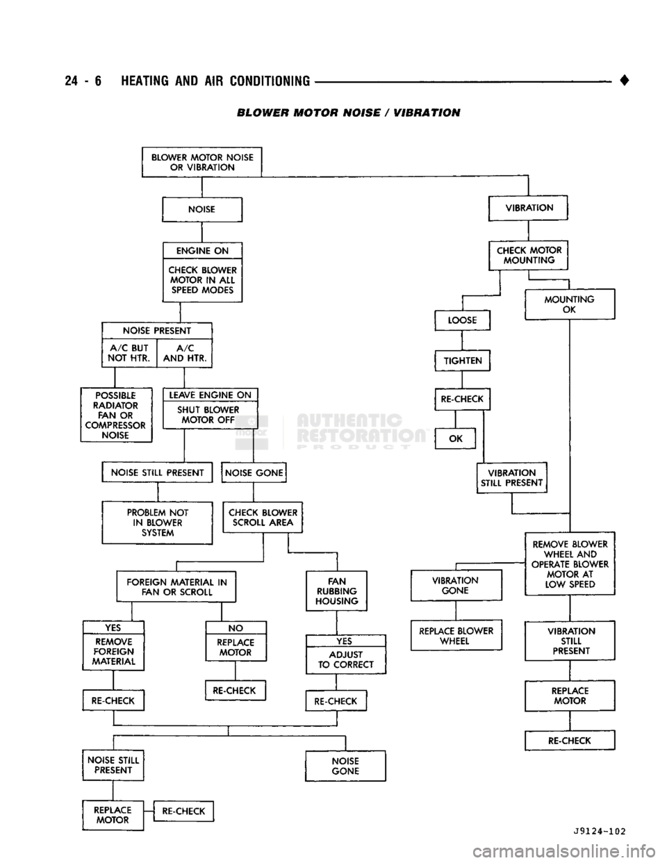
Refer to Heater Blower Motor/Control System Di
agnosis (Electrical) Chart and Blower Motor Noise/
Vibration Chart.
Page 1441 of 1502
24
- 4
HEATING
AND
AIR
CONDITIONING
•
(1) Possible location or cause of blower motor vi
bration are as follows:
(a) Blower motor assembly loose in heater A/C
housing.
(b) Blower wheel loose on motor shaft.
(c) Blower wheel out of balance or bent.
(d) Blower motor defective.
(2) Possible location or cause of blower motor noise
are as follows: (To verify blower noise disconnect blower motor wire lead connector and operate heater
or A/C system. If noise goes away, proceed with pro
cedure.)
(a) Refer to vibration section of this procedure.
(b) Foreign material in Heater-A/C housing
around blower wheel.
(c) Blower wheel rubbing Heater-A/C housing.
(d) Blower motor defective.
HEATER
DIAGNOSIS
(MECHANICAL)
INSUFFICIENT
HEAT
OBSTRUCTED HEATER OUTLETS
TEMPERATURE DOOR MISDIRECTED
OR BINDING, KINKED
OR
UNATTACHED
CONTROL CABLE (SEE CONTROL CABLE SECTION).
MODE DOOR IMPROPERLY ADJUSTED OR
BINDING. UNATTACHED CONTROL
CABLE.
±
OBSTRUCTED HEATER HOSE
•
KINKED HEATER HOSE, SEE ROUTING.
±
AIR
IN
HEATER CORE
LOW COOLANT FLOW, INSUFFICIENT COOLANT
IN
SYSTEM. DEFECTIVE
THERMOSTAT. WATER PUMP BELT LOOSE. GREATER
THAN
50%
MIXTURE
OF ANTIFREEZE. ENGINE TEMPERATURE LOW SEE GROUP
7.
ENGINE COOLING
DIAGNOSIS.
•
OBSTRUCTED INTAKE
IN
MANIFOLD
PASSAGE.
1_
HEATER CORE PLUGGED.
WATER VALVE PARTIALLY
OR
FULLY
CLOSED.
TOO
MUCH
HEAT
IMPROPERLY ADJUSTED TEMPERATURE CONTROL
CABLE.
DISCONNECTED
OR
BROKEN,
KINKED TEMPERATURE
CABLE.
BLEND-AIR
(TEMP)
DOOR
BINDING OR MISDIRECTED
ENGINE THERMOSTAT DEFECTIVE.
J9124-115
Page 1442 of 1502
![DODGE TRUCK 1993 Service Repair Manual
•
HEATING
AND
AIR
CONDITIONING
24 - 5 HEATER BLOWER MOTOR / CONTROL SYSTEM DIAGNOSIS (ELECTRICAL)
BLOWER
MOTOR
INOPERATIVE
]
[
INSPECT
FUSE
I- -*JT
FUSE
LOOKS
GOOD
CHECK
FOR](/manual-img/12/56922/w960_56922-1441.png "DODGE TRUCK 1993 Service Repair Manual
•
HEATING
AND
AIR
CONDITIONING
24 - 5 HEATER BLOWER MOTOR / CONTROL SYSTEM DIAGNOSIS (ELECTRICAL)
BLOWER
MOTOR
INOPERATIVE
]
[
INSPECT
FUSE
I- -*JT
FUSE
LOOKS
GOOD
CHECK
FOR")
•
HEATING
AND
AIR
CONDITIONING
24 - 5 HEATER BLOWER MOTOR / CONTROL SYSTEM DIAGNOSIS (ELECTRICAL)
BLOWER
MOTOR
INOPERATIVE
]
[
INSPECT
FUSE
I- -*JT
FUSE
LOOKS
GOOD
CHECK
FOR
STALLED MOTOR MOTOR
STALLED
REPLACE
MOTOR
REPLACE
FUSE
MOTOR
O.K. CHECK
FOR
SHORT
CORRECT
SHORT
REPLACE
FUSE
MOTOR
O.K. CHECK
FOR
SHORT
CORRECT
SHORT
REPLACE
FUSE
h
VOLTAGE
AT
BOTH
ENDS
OF
FUSE
CHECK
FOR
BATTERY VOLTAGE
AT BOTH ENDS
OF
FUSE
VOLTAGE
AT
BATTERY
SIDE
OF
FUSE ONLY
ATTACH
JUMPER
WIRE
BETWEEN
MOTOR GROUND WIRE
AND
BODY
OR
ENGINE
MOTOR
RUNS
LOCATE
AND
CORRECT
OPEN
CONNECTION
CHECK
BLOWER
REPLACE
MOTOR GROUND
FUSE
MOTOR DOES NOT
RUN
CHECK
MOTOR
CONTINUITY
IF MOTOR DOES NOT
RUN
REPLACE
MOTOR
MOTOR RUNS
ATTACH
JUMPER WIRE FROM
THE
MOTOR FEED WIRE
TO THE
POSITIVE POST
OF THE
BATTERY. MAKE SURE
THAT
MOTOR GROUND WIRE
IS
PROPERLY GROUNDED
FOR
THIS TEST.
REASSEMBLE
MOTOR WIRE CONNECTOR.
MAKE
SURE FEED
WIRE TERMINALS ARE
NOT BACKED
OUT OF
INSULATOR
OR OFF
CENTER
CHECK
RESISTOR
CONTINUITY
AND
RESISTOR
CONNECTIONS
VOLTAGE
AT
BATTERY LEAD CONNECTOR REMOVE WIRING CONNECTORS FROM RESISTOR TERMINALS.
MAKE
SURE
THAT
TERMINALS ARE
NOT
BACKED
OUT OF
INSULATOR.
CHECK
FOR
BATTERY VOLTAGE
IN
EACH
FAN
SWITCH POSITION.
REPLACE
SLOWER
SWITCH* VOLTAGE
IN
ALL SWITCH POSITIONS
CHECK
BLOWER SWITCH NO VOLTAGE
IN ONE OR
REPLACE
AND CONNECTIONS
MORE
SWITCH POSITIONS
RESISTOR
REMOVE WIRING CONNECTOR FROM SWITCH TERMINALS. MAKE
SURE
THE
TERMINALS ARE PROPERLY LOCKED
IN
SOCKETS
OF
INSULATOR. CHECK
FOR
BATTERY VOLTAGE
AT
BATTERY CONNECTOR
IN
THE INSULATOR.
BLOWER
MOTOR
DOES
NOT OPERATE AT
ALL SPEEDS
tfEl
J
RESISTOR
BLOCK
O.K.
CHECK
WIRING
CONNECTIONS AT
RESISTOR
BLOCK AND BLOWER SWITCH
IF DEFECTIVE,
REPLACE
BLOWER SWITCH INSPECT
BLOWER SWITCH INSPECT
RESISTOR
BLOCK
RESISTOR
BLOCK DEFECTIVE
REPLACE
RESISTOR BLOCK
*IF BLOWER SWITCH HAS FAILED DUE
TO
BURNING
OR
CHARRING,
CHECK
CURRENT DRAW
OF THE
BLOWER MOTOR.
J9124-101
Page 1443 of 1502
24
- 6
HEATING AND
AIR
CONDITIONING
BLOWER MOTOR NOISE / WIBRATION
BLOWER
MOTOR
NOISE
OR
VIBRATION
NOISE
VIBRATION
ENGINE
ON
CHECK BLOWER
MOTOR
IN
ALL
SPEED
MODES CHECK
MOTOR
MOUNTING
NOISE PRESEh
n
A/C BUT
NOT HTR. A/C
AND HTR.
POSSIBLE
RADIATOR FAN
OR
COMPRESSOR
NOISE LEAVE ENGINE
ON
SHUT
BLOWER
MOTOR
OFF
NOISE STILL PRESENT LO(
DSE
TIGHTEN
RE-CHECK
MOUNTING
OK
OK
NOISE GONE
PROBLEM
NOT
IN BLOWER SYSTEM
VIBRATION
STILL PRESENT
CHECK BLOWER
SCROLL
AREA
FOREIGN MATERIAL
IN
FAN
OR
SCROLL
YES
REMOVE
FOREIGN
MATERIAL FAN
RUBBING
HOUSING NO
REPLACE
MOTOR
RE-CHECK
VIBRATION
GONE
YES
A
TO
C
DJUST
ZORRECT RE-CHECK
REMOVE BLOWER
WHEEL AND
OPERATE BLOWER
MOTOR
AT
LOW SPEED REPLACE BLOWER
WHEEL
RE-CHECK
NOISE STILL PRESENT NOISE
GONE
VIBRATION
STILL
PRESENT
REPLACE
MOTOR
RE-CHECK REPLACE
MOTOR
RE-CHECK
J9124-102
Page 1444 of 1502
•
HEATING AND AIR CONDITIONING 24 - 7 AIR CONDITIONING SYSTEM
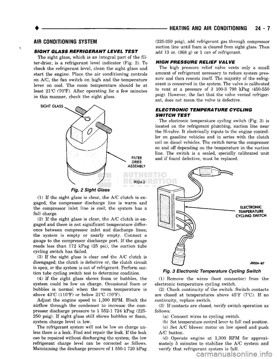
SIGHT GLASS REFRIGERANT LEWEL TEST The sight glass, which is an integral part of the fil
ter-drier, is a refrigerant level indicator (Fig. 2). To check the refrigerant level, clean the sight glass and
start the engine. Place the air conditioning controls
on A/C, the fan switch on high and the temperature lever on cool. The room temperature should be at
least 21°C (70°F). After operating for a few minutes
in this manner, check the sight glass.
SIGHT
GLASS
FILTER
DRIER
ASSEMBLY
9024-3
Fig.
2 Sight Glass
(1) If the sight glass is clear, the A/C clutch is en
gaged, the compressor discharge line is warm and
the compressor inlet line is cool; the system has a
full charge.
(2) If the sight glass is clear, the A/C clutch is en
gaged and there is not significant temperature differ
ence between compressor inlet and discharge lines;
the system is empty or nearly empty. Connect a gauge to the compressor discharge port. If the gauge
reads less than 172 kPag (25 psi), the suction tube cycling switch has failed.
(3) If the sight glass is clear and the A/C clutch is
disengaged; the clutch is defective or, the clutch circuit
is open, or the system is out of refrigerant. Perform suc
tion tube cycling switch test to determine condition.
(4) If the sight glass shows foam or bubbles, the
system could be low on charge. Occasional foam or
bubbles is normal when the room temperature is above 43°C (110°F) or below 21°C (70°F).
Adjust the engine speed to 1,300 RPM. Block the
airflow through the condenser to increase the com
pressor discharge pressure to 1 552-1 724 kPag (225- 250 psig). If sight glass still shows bubbles or foam,
system charge level is low. The refrigerant system will not be low on charge un
less there is a leak. Find and repair the leak. If the leak
can be repaired without discharging the system, the low
refrigerant charge level can be corrected as follows.
Maintaining the discharge pressure of 1 550-1 720 kPag (225-250 psig), add refrigerant gas through compressor
suction line until foam is cleared from sight glass. Then
add 13 oz. (368 g) or 1 can of refrigerant.
HIGH PRESSURE RELIEF
WALWE
The high pressure relief valve vents only a small
amount of refrigerant necessary to reduce system pres
sure and then reseats
itself.
The majority of the refrig
erant is conserved in the system. The valve is calibrated
to vent at a pressure of 3 100-3 790 kPag (450-550
psig).
However, the fact that the valve vented refriger ant, does not mean the valve is defective.
ELECTRONIC TEMPERATURE CYCLING
SWITCH TEST The electronic temperature cycling switch (Fig. 3) is
located on the refrigerant plumbing, suction line near
the H-valve. It electrically inputs to the engine control ler on gasoline vehicles and in series with the clutch
coil on diesel vehicles. The switch turns the compressor
on and off depending on the temperature in the suction
line.
The switch is a sealed, specially calibrated unit and if found defective, must be replaced.
ELECTRONIC
TEMPERATURE
CYCLING
SWITCH
J9324-97
Fig.
3 Electronic
Temperature
Cycling
Switch
(1) Remove the wires (boot connector) from the
electronic temperature cycling switch. (2) Check continuity of the switch. Switch contacts
are closed at temperatures above 45°F (7°C). If no
continuity, replace switch.
(3) If contacts are closed, verify switch operation as
follows:
(a) Connect wires to cycling switch.
(b) Set temperature control lever to full cool position. (c) Set A/C blower motor on low speed and push
A/C button.
(d) Operate engine at 1,300 RPM for approxi
mately 5 minutes to stabilize the A/C system and
verify that refrigerant system is full.
Page 1445 of 1502
24 - 8
HEATING
AND AIR
CONDITIONING
• (e) If compressor clutch cycles 3 to 10 times per
minute with temperature between 20°C-32°C (68°F-
90°F),
the cycling switch is normal. If the compressor
clutch fails to engage, check for continuity in the elec
trical circuit. Above 32°C (90°F) the compressor clutch
may be continuously engaged (non-cycling) due to the
high heat load. This condition is normal.
(4)
Refer to the Evaporator Heater Assembly for
the Removal/Installation procedures.
TESTING
THE
SYSTEM
FOR
LEAKS
If the air conditioning system is not cooling properly,
check that the refrigerant system is fully charged with
R-12.
Follow the procedures in the Sight Glass Refrig
erant Level Test section of this group.
If the refrigerant system is empty or low in refrig
erant charge, a leak at any of the line fittings or
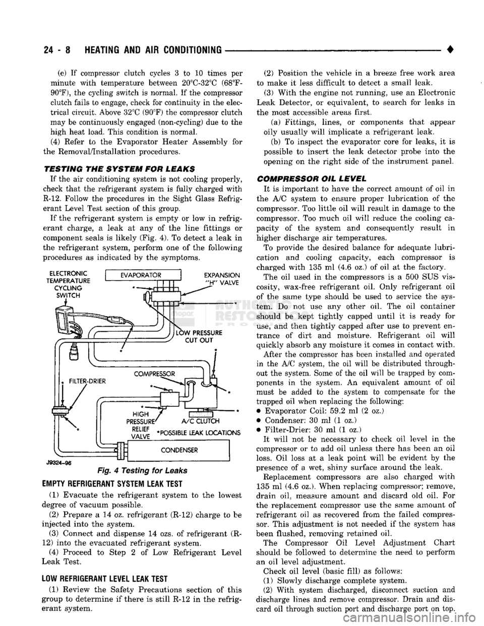
component seals is likely (Fig. 4). To detect a leak in
the refrigerant system, perform one of the following
procedures as indicated by the symptoms.
ELECTRONIC
TEMPERATURE CYCLING
SWITCH
EXPANSION
"H"
VALVE
J9324-96
Fig.
4 Testing for
Leaks
EMPTY REFRIGERANT SYSTEM LEAK TEST
(1) Evacuate the refrigerant system to the lowest
degree of vacuum possible.
(2) Prepare a 14 oz. refrigerant (R-12) charge to be
injected into the system. (3) Connect and dispense 14 ozs. of refrigerant (R-
12) into the evacuated refrigerant system, (4) Proceed to Step 2 of Low Refrigerant Level
Leak Test.
LOW REFRIGERANT LEVEL LEAK TEST
(1) Review the Safety Precautions section of this
group to determine if there is still R-12 in the refrig
erant system. (2) Position the vehicle in a breeze free work area
to make it less difficult to detect a small leak. (3) With the engine not running, use an Electronic
Leak Detector, or equivalent, to search for leaks in
the most accessible areas first.
(a) Fittings, lines, or components that appear
oily usually will implicate a refrigerant leak.
(b) To inspect the evaporator core for leaks, it is
possible to insert the leak detector probe into the opening on the right side of the instrument panel.
COMPRESSOR OIL LEVEL It is important to have the correct amount of oil in
the A/C system to ensure proper lubrication of the compressor. Too little oil will result in damage to the
compressor. Too much oil will reduce the cooling ca
pacity of the system and consequently result in
higher discharge air temperatures.
To provide the desired balance for adequate lubri
cation and cooling capacity, each compressor is
charged with 135 ml (4.6 oz.) of oil at the factory.
The oil used in the compressors is a 500 SUS vis
cosity, wax-free refrigerant oil. Only refrigerant oil of the same type should be used to service the sys
tem. Do not use any other oil. The oil container should be kept tightly capped until it is ready for
use,
and then tightly capped after use to prevent en
trance of dirt and moisture. Refrigerant oil will quickly absorb any moisture it comes in contact with.
After the compressor has been installed and operated
in the A/C system, the oil will be distributed through
out the system. Some of the oil will be trapped by com
ponents in the system. An equivalent amount of oil
must be added to the system to compensate for the
trapped oil when replacing the following: • Evaporator Coil: 59.2 ml (2 oz.)
• Condenser: 30 ml (1 oz.)
• Filter-Drier: 30 ml (1 oz.) It will not be necessary to check oil level in the
compressor or to add oil unless there has been an oil
loss.
Oil loss at a leak point will be evident by the
presence of a wet, shiny surface around the leak. Replacement compressors are also charged with
135 ml (4.6 oz.). When replacing compressor; remove,
drain oil, measure amount and discard old oil. For
the replacement compressor use the same amount of refrigerant oil as recovered from the failed compressor. This adjustment is not needed if the system has
been flushed, removing retained oil. The Compressor Oil Level Adjustment Chart
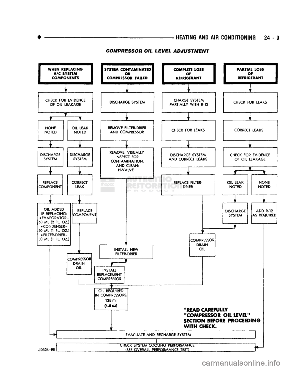
should be followed to determine the need to perform
an oil level adjustment. Check oil level (basic fill) as follows: (1) Slowly discharge complete system.
(2) With system discharged, disconnect suction and
discharge lines and remove compressor. Drain and dis card oil through suction port and discharge port on top.
Page 1446 of 1502
•
HEATING AND AIR CONDITIONING 24 - 9 COMPRESSOR OIL LEVEL ADJUSTMENT
WHEN
REPLACING
I
A/C SYSTEM
I
COMPONENTS
1
CHECK
FOR
EVIDENCE
OF
OIL
LEAKAGE
1
SYSTEM
COI
I
c
I COMPRESS
OTAMINATEI^
m 1
Ot FAILED
1
1
f
DISCHARGE SYSTEM
I
COMPLE
1
c
I
REFRIG TE LOSS
I
f 1
ERANT
1
i f
CHARGE SYSTEM
PARTIALLY
WITH
R-12 1
PARTIA
1
c
•
REFRIG L LOSS
1
)¥ I
ERANT
1
f
CHECK
FOR
LEAKS
NONE
NOTED
OIL LEAK
NOTED
r
DISCHARGE
SYSTEM
DISCHARGE
SYSTEM
r ] r
REPLACE
COMPONENT CORRECT
LEAK
OIL ADDED
IF REPLACING:
•
EVAPORATOR-
60 ML (2 FL. OZ.)
•
CONDENSER-
30 ML (1 FL. OZ.) •
FILTER-DRIER-
30 ML (1 FL. OZ.)
REPLACE
COMPONENT
COMPRESSOR
DRAIN OIL REMOVE FILTER-DRIER
AND COMPRESSOR CHECK
FOR
LEAKS
REMOVE, VISUALLY
INSPECT
FOR
CONTAMINATION,
AND CLEAN:
H-VALVE
1
1
DISCHARGE SYSTEM
AND CORRECT LEAKS
1
f
REPLACE
FILTER-
DRIER
INSTALL
NEW
FILTER-DRIER
COMPRESSOR
DRAIN OIL
INSTALL
REPLACEMENT
COMPRESSOR
OIL REQUIRED
IN COMPRESSORS: 136 ml
(4.6
oz) CORRECT LEAKS
CHECK
FOR
EVIDENCE OF
OIL
LEAKAGE
OIL LEAK
NOTED
NONE
NOTED
DISCHARGE
SYSTEM ADD
R-12
AS
REQUIRED
*READ
CAREFULLY
"COMPRESSOR
OIL
LEVEL"
SECTION
BEFORE
PROCEEDING
WITH
CHECK.
EVACUATE
AND
RECHARGE SYSTEM
J9324-98
CHECK SYSTEM COOLING PERFORMANCE
(SEE
OVERALL PERFORMANCE
TEST)
Page 1447 of 1502
24 - 10
HEATING
AND AIR
CONDITIONING
•
(3) Add 50 ml (1.7 oz.) of clean refrigerant oil
through the suction port.
(4) Install compressor.
(5) Install the suction and discharge lines to the
compressor. Use new gaskets to prevent leakage.
Tighten the line nuts to 23 N*m (200 in. lbs.) torque.
(6)
Evacuate and charge system.
OVER-ALL
PERFORMANCE
TEST
Humidity has an important bearing on the temper
ature of the air delivered to the vehicle's interior.
This is true of all air conditioning systems It is im
portant to understand the effect humidity has on the
performance of the system. When humidity is high,
the evaporator has to perform a double duty. It must lower the air temperature and the temperature of the
moisture carried in the air. Condensing the moisture
in the air transfers a great deal of heat energy into
the evaporator fins and tubing. This reduces the amount of heat the evaporator can absorb from the
air.
Evaporator capacity used to reduce the amount of
moisture in the air is not wasted. Wringing some of
the moisture out of the air entering the vehicle adds
to the comfort of the passengers. However, an owner may expect too much from their air conditioning sys
tem on humid days. A performance test is the best
way to determine whether or not the system is per
forming up to standard. This test also provides valu able clues to the possible cause of trouble.
To perform the test the air temperature in the test
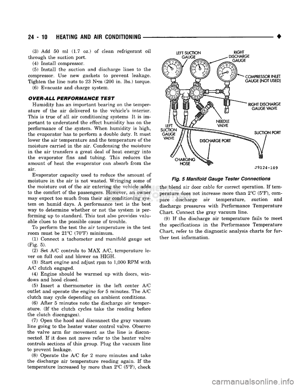
room must be 21°C (70°F) minimum. (1) Connect a tachometer and manifold gauge set
(Fig. 5).
(2) Set A/C controls to MAX A/C, temperature le
ver on full cool and blower on HIGH. (3) Start engine and adjust rpm to 1,000 RPM with
A/C clutch engaged.
(4) Engine should be warmed up with doors, win
dows and hood closed.
(5)
Insert a thermometer in the left center A/C
outlet and operate the engine for 5 minutes. The A/C
clutch may cycle depending on ambient conditions.
(6)
After 5 minutes note the discharge air temper
ature. (If the clutch cycles take the reading before
the clutch disengages).
(7) Open the hood and disconnect the gray vacuum
line going to the heater water control valve. Observe
the valve arm for movement as the line is discon nected. If it does not move refer to the heater valve
controls sections of this group. Plug the vacuum line
to prevent leakage.
(8) Operate the A/C for 2 more minutes and take
the discharge air temperature reading again. If the
temperature increased by more than 2°C (5°F), check
LEFT
SUCTION
RIGHT
J9124-109
Fig.
5 Manifold
Gauge
Tester
Connections
the blend air door cable for correct operation. If tem
perature does not increase more than 2°C
(5°F),
com
pare discharge air temperature, suction and discharge pressures with Performance Temperature Chart. Connect the gray vacuum line.
(9) If the discharge air temperature fails to meet
the specifications in the Performance Temperature Chart, refer to the diagnostic analysis charts for fur
ther test information.