1993 DODGE TRUCK heating
[x] Cancel search: heatingPage 272 of 1502
COOLING SYSTEM
CONTENTS page
DIAGNOSIS
... 4
ENGINE
ACCESSORY
DRIVE BELTS
40
ENGINE
BLOCK HEATERS
48
GENERAL
INFORMATION
Throughout this group, references are made to partic
ular vehicle models by alphabetical designation or by
the particular vehicle nameplate. A chart showing a
breakdown of alphabetical designations is included in
the Introduction section at the beginning of this man
ual.
5.9L gas powered engines will be' referred to as ei
ther: LDC (Light Duty Cycle) or HDC (Heavy Duty
Cycle).
COOLING
SYSTEM
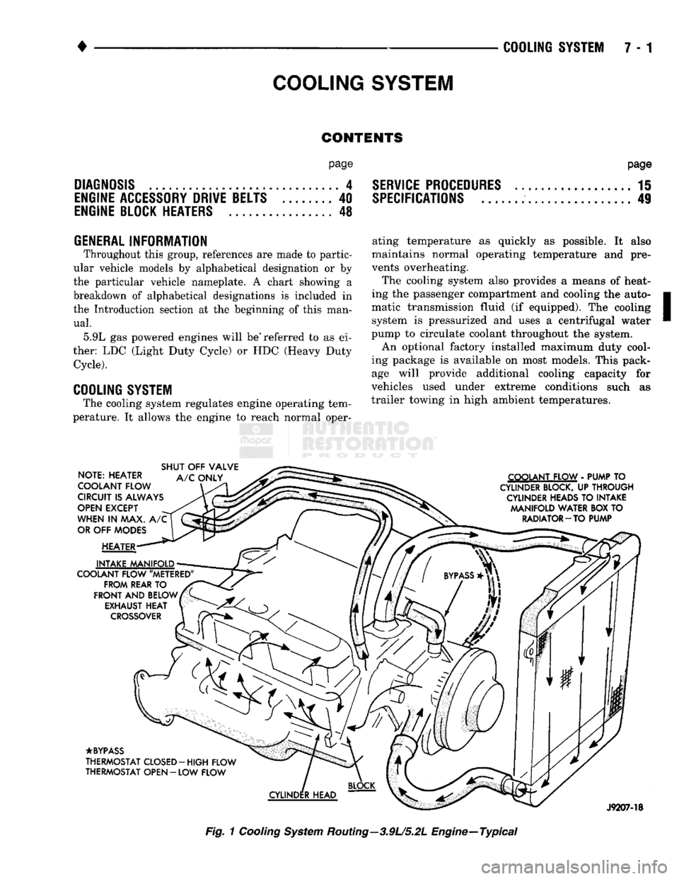
The cooling system regulates engine operating tem
perature. It allows the engine to reach normal oper-
page
SERVICE
PROCEDURES
15
SPECIFICATIONS
; 49
ating temperature as quickly as possible. It also
maintains normal operating temperature and pre
vents overheating.
The cooling system also provides a means of heat
ing the passenger compartment and cooling the auto
matic transmission fluid (if equipped). The cooling system is pressurized and uses a centrifugal water
pump to circulate coolant throughout the system.
An optional factory installed maximum duty cool
ing package is available on most models. This pack age will provide additional cooling capacity for
vehicles used under extreme conditions such as
trailer towing in high ambient temperatures.
NOTE: HEATER
COOLANT FLOW
CIRCUIT
IS
ALWAYS
OPEN
EXCEPT
WHEN
IN MAX. A/C
OR
OFF
MODES
HEATER
INTAKE MANIFOLD
COOLANT FLOW "METERED" FROM REAR
TO
FRONT
AND
BELOW EXHAUST
HEAT
CROSSOVER
SHUT
OFF
VALVE
A/C
ONLY COOLANT FLOW
-
PUMP
TO
CYLINDER BLOCK,
UP
THROUGH CYLINDER HEADS
TO
INTAKE MANIFOLD WATER
BOX TO
RADIATOR-TO PUMP
•BYPASS
THERMOSTAT CLOSED-HIGH FLOW
THERMOSTAT OPEN
- LOW
FLOW
J9207-18
Fig.
1
Cooling
System
Routing—3.9U5.2L Engine—Typical
Page 275 of 1502
DIAGNOSIS
PRELIMINARY
CHECKS
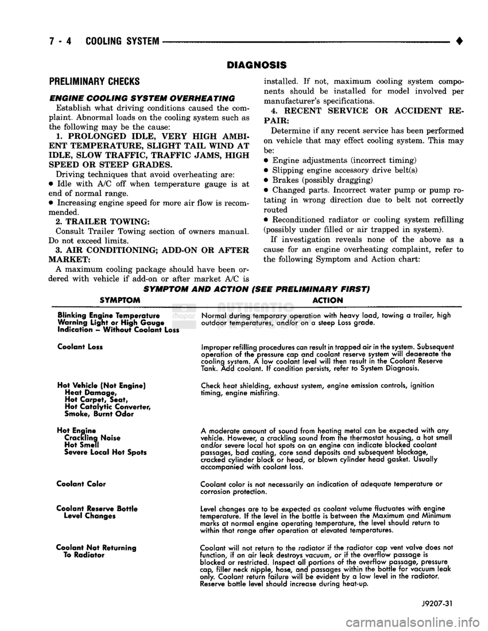
ENGINE COOLING SYSTEM OVERHEATING Establish what driving conditions caused the com
plaint. Abnormal loads on the cooling system such as
the following may be the cause:
1.
PROLONGED IDLE, VERY HIGH AMBI
ENT TEMPERATURE, SLIGHT TAIL WIND AT
IDLE, SLOW TRAFFIC, TRAFFIC JAMS, HIGH SPEED OR STEEP GRADES.
Driving techniques that avoid overheating are:
• Idle with A/C off when temperature gauge is at
end of normal range. * Increasing engine speed for more air flow is recom
mended.
2.
TRAILER TOWING: Consult Trailer Towing section of owners manual.
Do not exceed limits.
3.
AIR CONDITIONING; ADD-ON OR AFTER
MARKET: A maximum cooling package should have been or
dered with vehicle if add-on or after market A/C is
SYMPTOM AND ACTION
SYMPTOM
installed. If not, maximum cooling system compo
nents should be installed for model involved per
manufacturer's specifications.
4.
RECENT SERVICE OR ACCIDENT RE
PAIR:
Determine if any recent service has been performed
on vehicle that may effect cooling system. This may
be:
• Engine adjustments (incorrect timing)
• Slipping engine accessory drive belt(s) • Brakes (possibly dragging)
• Changed parts. Incorrect water pump or pump ro
tating in wrong direction due to belt not correctly
routed
• Reconditioned radiator or cooling system refilling (possibly under filled or air trapped in system).
If investigation reveals none of the above as a
cause for an engine overheating complaint, refer to
the following Symptom and Action chart:
PRELIMINARY FIRST) ACTION
Blinking Engine Temperature
Warning Light or High Gauge indication - Without Coolant Loss
Normal during temporary operation
with
heavy load, towing
a
trailer,
high
outdoor temperatures, and/or on
a
steep
Loss
grade.
Coolant Loss
Hot Vehicle (Not Engine) Heat Damage,
Hot Carpet, Seat,
Hot
Catalytic
Converter,
Smoke, Burnt Odor
Hot Engine Crackling Noise Hot Smell
Severe Local Hot Spots
Coolant Color
Coolant Reserve Bottle Level Changes
Coolant Not Returning To Radiator
Improper refilling procedures
can
result
in
trapped air
in
the
system.
Subsequent
operation
of the
pressure cap and coolant reserve system
will
deaereate
the
cooling
system.
A low
coolant
level
will
then result
in the
Coolant Reserve
Tank. Add coolant.
If
condition persists,
refer
to
System
Diagnosis.
Check
heat shielding, exhaust
system,
engine emission controls, ignition
timing, engine misfiring.
A
moderate amount
of
sound from heating
metal
can
be
expected
with
any
vehicle. However,
a
crackling sound from
trie
thermostat
housing,
a hot
smell and/or severe local
hot
spots on
an
engine can indicate blocked coolant
passages,
bad castina, core sand deposits and subsequent blockage,
cracked cylinder block
or
head,
or
blown cylinder head gasket. Usually
accompanied
with
coolant
loss.
Coolant
color is
not
necessarily
an
indication
of
adequate
temperature
or
corrosion
protection.
Level changes
are to be
expected as coolant volume fluctuates
with
engine
temperature.
If the
level
in the
bottle
is
between
the
Maximum and Minimum
marks
at
normal engine operating temperature,
the
level
should
return
to
within
that
range
after
operation
at
elevated temperatures.
Coolant
will
not
return
to the
radiator
if the
radiator cap vent valve does
not
function,
if
an
air
leak destroys vacuum,
or if the
overflow
passage
is
blocked
or
restricted. Inspect
all
portions
of the
overflow
passage,
pressure
cap,
filler
neck nipple, hose, and
passages
within
the
bottle
for
vacuum leak
only. Coolant
return
failure
will
be
evident
by a low
level
in the
radiator.
Reserve
bottle
level
should increase during heat-up.
J9207-31
Page 276 of 1502
•
COOLING
SYSTEM
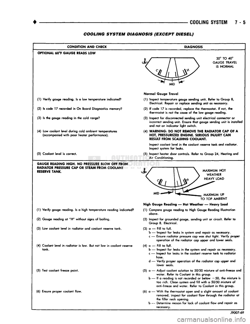
7 - 6 COOLING SYSTEM DIAGNOSIS (EXCEPT DIESEL)
CONDITION
AND
CHICK
OPTIONAL
M°¥
GAUGE
READS
LOW
(!) Verify
gauge
reading. Is a low temperature indicated?
(2) Is code 17 recorded in On Board
Diagnostics
memory?
(3) Is the
gauge
reading in the cold
range?
(4) Low coolant level during cold ambient temperatures
(accompanied
with poor heater performance).
(5) Coolant level is correct.
GAUGE
HEADING
HIGH.
NO
PRESSURE
BLOW
OFF
FROM
RADIATOR
PRESSURE
CAP
OR
STEAM
FROM
COOLANT
RESERVE
TANK.
(1) Verify
gauge
reading. Is a high temperature reading indicated?
(2)
Gauge
reading at
"H"
without
signs
of boiling.
(3) Low coolant level in radiator and coolant reserve tank.
(4) Coolant level in radiator is low. But not low in coolant reserve tank.
(5) Test coolant
freeze
point.
(6) Ensure proper coolant flow.
DIAGNOSIS
30° TO 40°
GAUGE
TRAVEL
IS
NORMAL
Normal
Gauge
Travel
(1) Inspect temperature
gauge
sending
unit. Refer to Group 8, Electrical. Repair or replace sending unit as necessary.
(2) If code 17 is recorded, replace the thermostat. If not, the thermostat is not the
cause
of the low
gauge
reading.
(3) Inspect for
disconnected
sending
unit electrical connector or incorrect
sending
unit. Ensure that
gauge
sending
unit is installed
and
not an indicator light switch.
(4)
WARNING:
DO NOT
REMOVE
THE
RADIATOR
CAP
OF A
HOT,
PRESSURIZED
ENGINE.
SERIOUS
INJURY
CAN
RESULT
FROM
SCALDING
COOLANT.
Inspect
coolant level in the coolant reserve tank and radiator.
Inspect
system
for leaks.
(5) Inspect heater door
controls.
Refer to Group 24, Heating and
Air
Conditioning.
TO
TOP
AMBIENT
High
Gauge
Reading
— Hot Weather — Heavy Load
(1) Compare
gauge
reading to
High
Gauge
Reading Illustration
above.
(2) Inspect for grounded
gauge,
sending
unit or circuit. Refer to
Group
8, Electrical.
(3) a — Pill to full.
b
— Inspect for leaks in
system
and repair as
necessary,
c
—
Ensure
radiator pressure cap was shut tight. Verify
proper
operation of the radiator cap upper and lower
seals.
(4) a —
Fill
to full,
b
— Inspect for leaks in the
system
and repair as
necessary,
c
— Inspect for leaks in the coolant reserve tank to radiator
hose.
d
— Verify proper operation of the radiator cap upper and lower
seals.
(5) a — Adjust coolant solution to
50/50
mixture of anti-freeze and water. Refer to Coolant in this
group,
b
— If a reading is not recorded or below
—
50, the mixture is
too
rich. Clean
system
and
fill
with a
50/50
mixture of
anti-freeze and water. Refer to Coolant in this
group.
(6) a •— With the thermostat open and a slight amount of coolant
removed,
inspect for coolant flow through the radiator at
the
filler
neck opening,
b
— Determine reason for lack of coolant flow and repair as
necessary.
J9007-69
Page 281 of 1502
7-10 COOLING SYSTEM
•
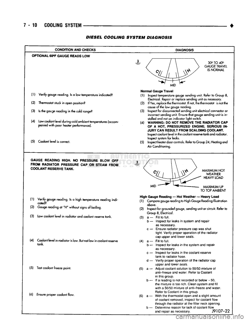
DIESEL
COOLING SYSTEM
DIAGNOSIS
CONDITION AND CHECKS
DIAGNOSIS
OPTIONAL
60»F
GAUGE
READS
LOW 30° TO 40°
GAUGE
TRAVEL
IS
NORMAL
(1)
Verify
gauge reading. Is a low
temperature
indicated?
(2) Thermostat stuck in open position?
(3) Is the gauge reading in the cold range?
(4) Low coolant
level
during cold ambient temperatures (accom panied
with
poor
heater
performance).
(5) Coolant
level
is correct.
MID
Normal
Gauge
Travel
(1) Inspect
temperature
gauge sending unit. Refer to Group 8,
Electrical. Repair or replace sending
unit
as necessary.
(2) If
Yes,
replace the thermostat. If not, the thermostat is not the
cause
of the low gauge
reading.
(3) Inspect for disconnected sending
unit
electrical
connector or
incorrect
sending unit. Ensure
that
gauge sending
unit
is in
stalled and not an indicator light switch.
(4) WARNING: DO NOT REMOVE THE RADIATOR CAP
OF
A HOT, PRESSURIZED ENGINE. SERIOUS IN
JURY CAN RESULT FROM SCALDING COOLANT. Inspect coolant
level
in the coolant reserve tank and radiator. Inspect system for leaks.
(5) Inspect
heater
door
controls.
Refer to Group 24, Heating and
Air Conditioning.
GAUGE
READING HIGH. NO PRESSURE BLOW OFF FROM RADIATOR PRESSURE CAP OR STEAM FROM
COOLANT
RESERVE
TANK.
X
(1)
Verify
gauge reading. Is a high
temperature
reading indi
cated?
(2) Gauge reading at "H"
without
signs
of boiling.
(3) Low coolant
level
in radiator and coolant reserve tank.
MAXIMUM
HOT
WEATHER
HEAVY
LOAD
MAXIMUM
UP
TO
TOP AMBIENT High Gauge
Reading
— Hot
Weather
—
Heavy
Load
(1) Compare gauge reading to High Gauge Reading Illustration
above.
(2) Inspect for grounded
gauge,
sending
unit
or circuit. Refer to
Group
8, Electrical.
(4) Coolant
level
in radiator
is
low.
But
not low in coolant reserve tank.
(5) Test coolant
freeze
point. (3) a-
b — (4) a-
b —
d —
(5) a- (6) Ensure proper coolant flow.
(6) a-
b —
Fill
to
full.
Inspect for leaks in system and
repair
as
necessary.
Ensure
radiator pressure cap was shut
tight.
Verify
proper operation of the radiator
cap
upper and lower
seals.
Fill
to
full.
Inspect for leaks in the system and
repair
as
necessary.
Inspect for leaks in the coolant reserve
tank to radiator hose.
Verify
proper operation of the radiator cap
upper and lower
seals.
Adjust coolant solution to
50/50
mixture
of
anti-freeze
and
water.
Refer to Coolant
in this group. If a reading is not recorded or below - 50.
the
mixture
is too rich. Clean system and
fill
with
a
50/50
mixture
of
anti-freeze
and
water.
Refer to Coolant in this group.
With the thermostat open and a slight amount
of coolant removed, inspect for coolant flow
through the radiator at the
filler
neck opening. Determine reason for lack of coolant flow
and
repair
as necessary.
J9107-22
Page 291 of 1502

7 - 20
COOLING
SYSTEM
•
HOSE
CLAMP
HOSE
J9207-36
Fig.
16
Hose
Clamp
Tool
WITH AIR
CONDITIONING
(A/C)
REMOVAL
If equipped with A/C, the generator and A/C com
pressor along with their common mounting bracket (Fig. 17) must be partially removed. Removing the
generator or A/C compressor from their mounting
bracket is not necessary. Also, discharging the A/C system is not necessary. Do not remove any refrig
erant lines from A/C compressor.
SUPPORT BRACKET (ROD)
GENERATOR/COMPRESSOR
MOUNTING
BRACKET
J9307-66
Fig.
17 Generator—A/C
Compressor
Mounting
Bracket—
Typical
WARNING;
THE A/C
SYSTEM
IS
UNDER
PRESSURE
EVEN
WITH
THE
ENGINE OFF. REFER
TO
REFRIG
ERANT
WARNINGS
IN
GROUP
24,
HEATING
AND
AIR
CONDITIONING.
(1) Disconnect negative battery cable from battery. (2) Partially drain cooling system. Refer to Drain
ing Cooling System in this group.
Do not waste reusable coolant. If the solution is
clean, drain the coolant into a clean container for re
use.
(3) Remove upper radiator hose clamp at radiator.
Special Clamp Tool number 6094 (Fig. 16) may be
used to remove the constant tension clamps. Remove
hose at radiator.
(4) Disconnect throttle cable from clip at radiator
fan shroud. (5) Unplug wiring harness from A/C compressor.
(6) Remove the air cleaner assembly.
(7) Remove accessory drive belt. Refer to Belt Re
moval/Installation in the Engine Accessory Drive
Belt section of this group.
(8) 3.9L/5.2L/5.9L LDC-Gas: The drive belt idler
pulley must be removed to gain access to one of the
A/C compressor/generator bracket mounting bolts. Remove the idler pulley bolt and remove idler pulley (Fig. 18).
GENERATOR/COMPRESSOR
AND
BRACKET
SUPPORT BRACKET
IGNITION
COIL
BRACKET
Fig.
18 Idler Pulley-3.9U5.2U5.9L
LDC-Gas
Engine
5.9L HDC-Gas: The automatic belt tensioner/pul-
ley assembly must be removed to gain access to one
of the A/C compressor/generator bracket mounting
bolts.
Remove the tensioner mounting bolt (Fig. 19) and remove tensioner.
(9) Remove the engine oil dipstick tube mounting
bolt at the side of the A/C-generator mounting
bracket.
(10) Disconnect throttle body control cables. Refer
to Accelerator Pedal and Throttle Cable in Group 14,
Fuel System.
Page 301 of 1502

7 - 30
COOLING
SYSTEM
•
COOLING
SYSTEM
Fig.
39
Pressure
Testing
Cooling
System—Typical bulges while testing, replace as necessary. Observe
gauge pointer and determine condition of cooling sys
tem according to following criteria:
Holds Steady: If pointer remains steady for two
minutes, serious coolant leaks are not present in sys
tem. However, there could be an internal leak that does not appear with normal system test pressure. If
it is certain that coolant is being lost and leaks can
not be detected, inspect for interior leakage or per
form Internal Leakage Test.
Drops Slowly: Indicates a small leak or seepage is
occurring. Examine all connections for seepage or
slight leakage with a flashlight. Inspect radiator,
hoses,
gasket edges and heater. Seal small leak holes
with a Sealer Lubricant (or equivalent). Repair leak
holes and inspect system again with pressure ap
plied.
Drops Quickly: Indicates that serious leakage is
occurring. Examine system for external leakage. If
leaks are not visible, inspect for internal leakage.
Large radiator leak holes should be repaired by a
reputable radiator repair shop.
INTERNAL LEAKAGE INSPECTION Remove engine oil pan drain plug and drain a
small amount of engine oil. If coolant is present in
the pan, it will drain first because it is heavier than
oil.
An alternative method is to operate engine for a
short period to churn the oil. After this is done, re
move engine dipstick and inspect for water globules.
Also inspect transmission dipstick for water globules and transmission fluid cooler for leakage.
WARNING:
WITH
PRESSURE TESTER TOOL
7700
INSTALLED
ON
RADIATOR,
DO
NOT ALLOW
PRES
SURE
TO
EXCEED
110 KPA (20
PSI). PRESSURE
WILL
BUILD
UP
QUICKLY
IF A
COMBUSTION LEAK
IS
PRESENT.
TO
RELEASE
PRESSURE,
ROCK
TESTER
FROM SIDE
TO
SIDE. WHEN REMOVING
TESTER,
DO NOT
TURN TESTER MORE THAN
1/2
TURN
IF
SYSTEM
IS
UNDER
PRESSURE.
Operate engine without pressure cap on radiator
until thermostat opens. Attach a Pressure Tester to
filler neck. If pressure builds up quickly it indicates a combustion leak exists. This is usually the result of
a cylinder head gasket leak or crack in engine. Re
pair as necessary.
If there is not an immediate pressure increase,
pump the Pressure Tester. Do this until indicated
pressure is within system range of 110 kPa (16 psi). Fluctuation of gauge pointer indicates compression or
combustion leakage into cooling system.
Because the vehicle is equipped with a catalytic
converter, do not remove spark plug cables or short
out cylinders (non-diesel engines) to isolate compres
sion leak.
If the needle on dial of pressure tester does not
fluctuate, race engine a few times to check for an ab normal amount of coolant or steam. This would be
emitting from exhaust pipe. Coolant or steam from
exhaust pipe may indicate a faulty cylinder head
gasket, cracked engine cylinder block or cylinder
head. A convenient check for exhaust gas leakage into
cooling system is provided by a commercially avail able Block Leak Check tool. Follow manufacturers
instructions when using this product.
COMBUSTION LEAKAGE TEST-WITHOUT
PRESSURE TESTER DO NOT WASTE reusable coolant. If solution is
clean, drain coolant into a clean container for reuse.
WARNING:
DO NOT
REMOVE CYLINDER BLOCK DRAIN PLUGS
OR
LOOSEN RADIATOR DRAIN-
COCK
WITH
SYSTEM
HOT AND
UNDER PRES
SURE.
SERIOUS BURNS FROM COOLANT
CAN
OCCUR.
Drain sufficient coolant to allow thermostat re
moval. Refer to Thermostat Replacement. Disconnect
water pump drive belt. Add coolant to radiator to bring level to within 6.3
mm (1/4 in) of top of thermostat housing.
CAUTION:
Avoid
overheating.
Do not
operate
en
gine
for an
excessive
period
of
time.
Open
drain-
cock
immediately
after
test
to
eliminate
boil
over.
Start engine and accelerate rapidly three times, to
approximately 3000 rpm while observing coolant. If
internal engine combustion gases% are leaking into
cooling system, bubbles will appear in coolant. If
bubbles do not appear, internal combustion gas leak age is not present.
COOLANT
RESERVE/0WERFL0W
SYSTEM
The coolant reserve/overflow system (Fig. 40 or 41)
works in conjunction with the radiator pressure cap.
Page 309 of 1502
7 - 38
COOLING
SYSTEM
•
WARNING:
DO NOT
ATTEMPT
TO
BEND
OR
STRAIGHTEN
FAN
BLADES
IF
NOT WITHIN
SPECI
FICATIONS.
(4) Inspect fan assembly for cracks, bends, loose
rivets or broken welds. Replace fan if any damage is
found.
CAUTION; If the fan
blade assembly
is
replaced
be
cause
of
mechanical damage,
the fan
pulley
and
viscous
fan
drive should also
be
inspected.
These
components
could have been damaged
due to ex
cessive
vibration.
INSTALLATION
(1) Install fan blade assembly to viscous fan drive.
Tighten mounting bolts.
(2) Position the fan shroud and fan blade/viscous
fan drive to the vehicle as an assembly.
(3) Install viscous fan drive assembly on fan hub
shaft. Tighten mounting nut to 57 N*m (42 ft. lbs.)
torque.
(4) Install fan shroud bolts.
(5) Install battery cable to battery.
VISCOUS
FAN
DRIVE
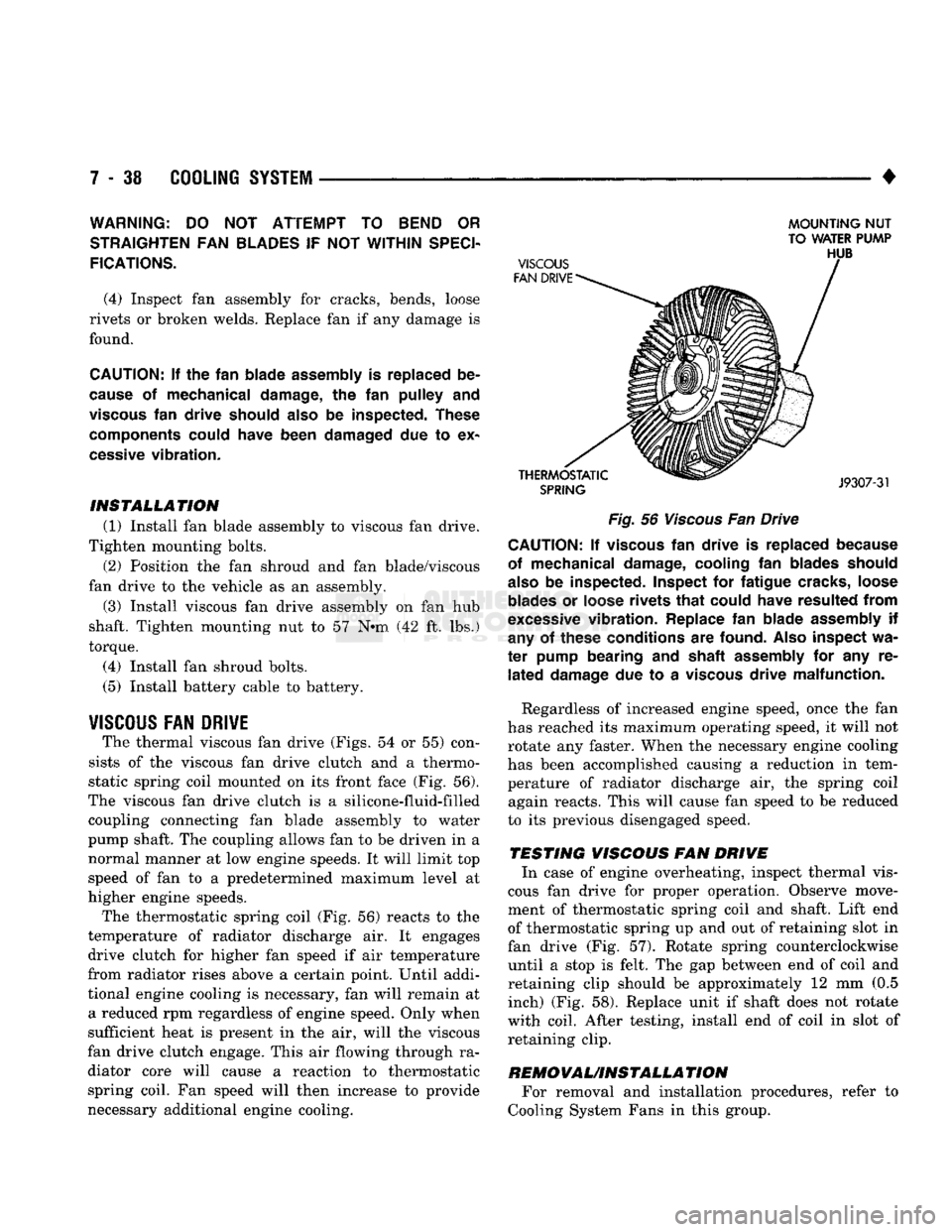
The thermal viscous fan drive (Figs. 54 or 55) con
sists of the viscous fan drive clutch and a thermo
static spring coil mounted on its front face (Fig. 56).
The viscous fan drive clutch is a silicone-fluid-filled coupling connecting fan blade assembly to water
pump shaft. The coupling allows fan to be driven in a normal manner at low engine speeds. It will limit top
speed of fan to a predetermined maximum level at
higher engine speeds.
The thermostatic spring coil (Fig. 56) reacts to the
temperature of radiator discharge air. It engages drive clutch for higher fan speed if air temperature
from radiator rises above a certain point. Until addi
tional engine cooling is necessary, fan will remain at a reduced rpm regardless of engine speed. Only when
sufficient heat is present in the air, will the viscous
fan drive clutch engage. This air flowing through ra diator core will cause a reaction to thermostatic spring coil. Fan speed will then increase to provide
necessary additional engine cooling.
MOUNTING
NUT
TO WATER PUMP
Fig.
56
Viscous
Fan Drive CAUTION; If
viscous
fan
drive
is
replaced because
of mechanical damage, cooling
fan
blades should
also
be
inspected. Inspect
for
fatigue cracks, loose
blades
or
loose rivets
that
could have resulted
from
excessive
vibration. Replace
fan
blade assembly
if
any
of
these conditions
are
found.
Also
inspect
wa
ter
pump bearing
and
shaft assembly
for any re
lated
damage
due to a
viscous
drive malfunction.
Regardless of increased engine speed, once the fan
has reached its maximum operating speed, it will not
rotate any faster. When the necessary engine cooling
has been accomplished causing a reduction in tem perature of radiator discharge air, the spring coil again reacts. This will cause fan speed to be reduced
to its previous disengaged speed.
TESTING VISCOUS FAN DRIVE In case of engine overheating, inspect thermal vis
cous fan drive for proper operation. Observe move
ment of thermostatic spring coil and shaft. Lift end
of thermostatic spring up and out of retaining slot in
fan drive (Fig. 57). Rotate spring counterclockwise until a stop is felt. The gap between end of coil and
retaining clip should be approximately 12 mm (0.5 inch) (Fig. 58). Replace unit if shaft does not rotate
with coil. After testing, install end of coil in slot of retaining clip.
REMOVAUINSTALLA
TION For removal and installation procedures, refer to
Cooling System Fans in this group.
Page 311 of 1502
ENGINE ACCESSORY DRIVE BELTS
INDEX
page
Automatic Belt Tensioner
45
Belt Diagnosis
40
Belt Removal/Installation
. 40
page
Belt Schematics
40
Belt Tension
40
General
Information
40
GENERAL
INFORMATION
All vehicles are available with either
a
3.9L (V-6),
a 5.2L (V-8),
a
5.9L (gas V-8) or
a
5.9L (in-line 6 cyl
inder diesel) engine. The accessory drive components
are
operated
by a
single, crankshaft driven, serpentine drive belt on all
engines. An automatic belt tensioner
is
used to main
tain correct belt tension
at all
times. Refer
to
Auto matic Belt Tensioner proceeding
in
this group.
BELT DIAGNOSIS SERPENTINE DRIVE BELT DIAGNOSIS-ALL
ENGINES
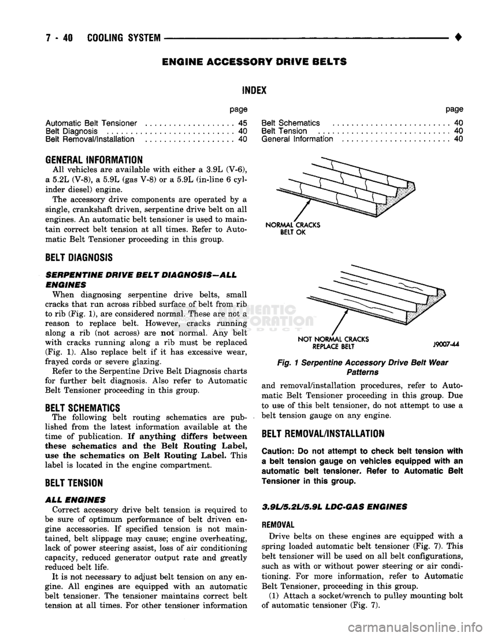
When diagnosing serpentine drive belts, small
cracks that run across ribbed surface of belt from rib
to rib (Fig. 1), are considered normal. These are not
a
reason
to
replace belt. However, cracks running along
a rib (not
across)
are not
normal.
Any
belt
with cracks running along
a rib
must
be
replaced (Fig.
1).
Also replace belt
if it has
excessive wear,
frayed cords
or
severe glazing.
Refer to the Serpentine Drive Belt Diagnosis charts
for further belt diagnosis. Also refer
to
Automatic Belt Tensioner proceeding
in
this group.
BELT SCHEMATICS
The following belt routing schematics
are
pub
lished from
the
latest information available
at the
time
of
publication.
If
anything differs between
these schematics
and the
Belt Routing Label,
use
the
schematics
on
Belt Routing Label. This
label
is
located
in
the engine compartment.
BELT TENSION
ALL
ENGINES
Correct accessory drive belt tension
is
required
to
be sure
of
optimum performance
of
belt driven
en
gine accessories.
If
specified tension
is not
main
tained, belt slippage may cause; engine overheating, lack
of
power steering assist, loss
of
air conditioning
capacity, reduced generator output rate and greatly
reduced belt life.
It
is
not necessary
to
adjust belt tension on any en
gine.
All
engines
are
equipped with
an
automatic
belt tensioner. The tensioner maintains correct belt tension
at all
times. For other tensioner information
NORMAL CRACKS
BELT
OK
NOT NORMAL CRACKS
REPLACE
BELT
J9007-44
Fig. 1 Serpentine Accessory Drive Belt Wear Patterns
and removal/installation procedures, refer
to
Auto
matic Belt Tensioner proceeding
in
this group.
Due
to use
of
this belt tensioner, do not attempt
to
use
a
belt tension gauge
on
any engine.
BELT REMOVAL/INSTALLATION
Caution:
Do not
attempt
to
check belt tension with
a
belt
tension gauge
on
vehicles equipped with
an
automatic belt tensioner. Refer
to
Automatic Belt
Tensioner
in
this
group.
3.9L/5,2U5*9L
LDC-GAS ENGINES
REMOVAL
Drive belts
on
these engines
are
equipped with
a
spring loaded automatic belt tensioner (Fig.
7).
This
belt tensioner will
be
used on
all
belt configurations, such
as
with
or
without power steering
or
air condi
tioning.
For
more information, refer
to
Automatic Belt Tensioner, proceeding
in
this group.
(1) Attach
a
socket/wrench
to
pulley mounting bolt
of automatic tensioner (Fig.
7).