1993 DODGE TRUCK torque
[x] Cancel search: torquePage 1278 of 1502
•
TRANSMISSION
OVERHAUL-42RH
21 - 277 (47) Lubricate intermediate shaft splines and bushing
surfaces with transmission fluid or petroleum jelly.
(48) Install overdrive unit. Be sure governor tubes
are aligned with feed holes in piston retainer boss. Note that intermediate shaft is snug fit in overdrive
planetary gear and overrunning clutch. If overdrive unit will not seat fully, rotate overdrive output shaft slightly to align splines and try again.
(49) Apply 1-2 drops of Mopar thread adhesive (or
Loctite 242) to overdrive unit attaching bolts. Then install and tighten bolts to 34 N« (25 ft. lbs.) torque.
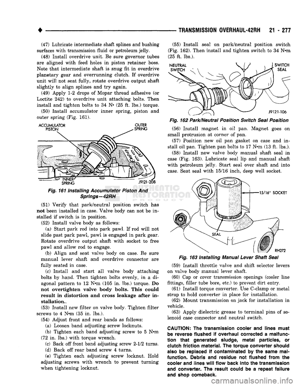
(50) Install accumulator inner spring, piston and
outer spring (Fig. 161).
ACCUMULATOR
OUTER
Fig.
161 Installing
Accumulator
Piston
And
Springs—42RH
(51) Verify that park/neutral position switch has
not been installed in case. Valve body can not be in stalled if switch is in position.
(52) Install valve body as follows: (a) Start park rod into park pawl. If rod will not
slide past park pawl, pawl is engaged in park gear.
Rotate overdrive output shaft with socket to free
pawl and allow rod to engage.
(b) Align and seat valve body on case. Be sure
manual lever shaft and overdrive connector are
fully seated in case.
(c) Install and start all valve body attaching
bolts by hand. Then tighten bolts evenly, in a di agonal pattern to 12 N»m (105 in. lbs.) torque. Do
not overtighten valve body bolts. This could
result in distortion and cross leakage after in stallation..
(53) Install new filter on valve body. Tighten filter
screws to 4 N*m (35 in. lbs.).
(54) Adjust front and rear bands as follows: (a) Loosen band adjusting screw locknuts.
(b) Tighten each band adjusting screw to 5 Nnn
(72 in. lbs.) with torque wrench.
(c) Back off front band adjusting screw 2-1/2 turns.
(d) Back off rear band screw 4 turns.
(e) Tighten each adjusting screw locknut. Hold
adjusting screws with wrench to prevent turning
when tightening locknut. (55) Install seal on park/neutral position switch
(Fig. 162). Then install and tighten switch to 34 N«m
(25 ft. lbs.).
Fig.
162 Park/Neutral Position
Switch
Seal
Position
(56) Install magnet in oil pan. Magnet goes on
small protrusion at corner of pan. (57) Position new oil pan gasket on case and in
stall oil pan. Tighten pan bolts to 17 N*m (13 ft. lbs.).
(58) Install new valve body manual shaft seal in
case (Fig. 163). Lubricate seal lip and manual shaft
with petroleum jelly. Start seal over shaft and into
case.
Seat seal with 15/16 inch, deep well socket.
(59) Install throttle valve and shift selector levers
on valve body manual lever shaft. (60) Cap or cover transmission openings (cooler line
fittings, filler tube bore, etc.) to prevent dirt entry.
(61) Install torque converter. Use C-clamp or metal
strap to hold converter in place for installation. (62) Mount transmission on jack for installation in
vehicle.
(63) Apply dielectric grease to terminal pins of so
lenoid case connector and neutral switch.
CAUTION:
The
transmission
cooler
and
lines
must
be
reverse
flushed
if
overhaul
corrected
a
malfunc
tion
that
generated
sludge,
metal
particles,
or
clutch
friction
material.
The
torque
converter
should
also
be replaced if
contaminated
by the
same
mal
function.
Debris and
residue
not
flushed
from
the
cooler
and
lines
will
flow
back
into
the
transmission
and
converter.
The
result
could
be a
repeat
failure
and
shop
comeback.
Page 1279 of 1502
21
- 278
TRANSMISSION
0VERHAUL-4IRH
•
TRANSMISSION OWERHAUL-46RH
INDEX
page
Accumulator Overhaul
288
Front Clutch Overhaul
293
Front Servo
and
Band Overhaul
............
289
Oil Pump
and
Reaction Shaft Support Overhaul
. 289
Overdrive Piston
and
Retainer Service
286
Overhaul Service
Information
285
Overrunning Clutch Overhaul
286
Planetary Geartrain Overhaul
...............
297
TRANSMISSION
DISASSEMBLY
(1) Remove torque converter,
if not
previously
re
moved. (2) Clean transmission exterior with steam
gun or
solvent. Wear safety goggles while cleaning trans
mission. (3) Remove shift
and
throttle levers from shaft
of
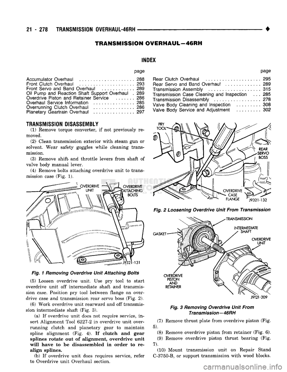
valve body manual lever. (4) Remove bolts attaching overdrive unit
to
trans
mission case
(Fig. 1).
Fig.
1
Removing
Overdrive Unit Attaching
Bolts
(5) Loosen overdrive unit.
Use pry
tool
to
start
overdrive unit
off
intermediate shaft
and
transmis
sion case. Position
pry
tool between flange
on
over
drive case
and
transmission rear servo boss
(Fig. 2).
(6) Work overdrive unit rearward
and off
transmis
sion intermediate shaft
(Fig. 3).
(a)
If
overdrive unit does
not
require service,
in
sert Alignment Tool 6227-2
in
overdrive unit over
running clutch
and
planetary gear
to
maintain spline alignment
(Fig. 4). If
clutch
and
gear splines rotate
out of
alignment, overdrive unit
will have
to be
disassembled
in
order
to re
align splines. (b)
If
overdrive unit does requires service, refer
to Overdrive unit Overhaul section.
page
Rear
Clutch Overhaul
295
Rear
Servo
and
Band Overhaul
. 289
Transmission
Assembly
...................
315
Transmission
Case
Cleaning
and
Inspection
. . . 285
Transmission
Disassembly
278
Valve
Body Cleaning
and
Inspection
308
Valve
Body Service
and
Adjustment
. 302
Fig.
2
Loosening
Overdrive Unit From
Transmission
J9121-209
Fig.
3
Removing
Overdrive Unit From
Transmission—46RH
(7) Remove thrust plate from overdrive piston
(Fig.
5). (8)
Remove overdrive piston from retainer
(Fig. 6).
(9)
Remove overdrive pistop thrust bearing
(Fig.
7).
(10) Mount transmission unit
on
Repair Stand
C-3750-B,
or
support transmission with wood blocks.
Page 1289 of 1502
21
- 288
TRANSMISSION OVERHAUL-48RH
Fig.
44
Positioning
Puller
Plate
On
Clutch
Cam
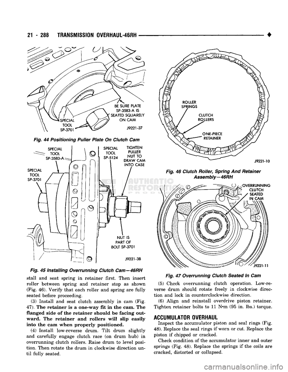
Fig.
45 Installing Overrunning
Clutch
Cam—46RH
stall and seat spring in retainer first. Then insert
roller between spring and retainer stop as shown (Fig. 46). Verify that each roller and spring are fully
seated before proceeding.
(3) Install and seat clutch assembly in cam (Fig.
47).
The retainer is a one-way fit in the cam. The
flanged side of the retainer should be facing out ward. The retainer and rollers will slip easily
into the cam when properly positioned.
(4) Install low-reverse drum. Tilt drum slightly
and carefully engage clutch race (on drum hub) in
overrunning clutch rollers. Raise drum to level posi
tion. Then rotate the drum in clockwise direction un
til fully seated. •
Fig.
47 Overrunning
Clutch
Seated In Cam (5) Check overrunning clutch operation. Low-re
verse drum should rotate freely in clockwise direc
tion and lock in counterclockwise direction.
(6) Align and reinstall overdrive piston retainer.
Tighten retainer bolts to 11 N*m (95 in. lbs.) torque.
ACCUMULATOR OVERHAUL
Inspect the accumulator piston and seal rings (Fig.
48).
Replace the seal rings if worn or cut. Replace the
piston if chipped or cracked. Check condition of the accumulator inner and outer
springs (Fig. 48). Replace the springs if the coils are
cracked, distorted or collapsed.
Page 1293 of 1502
21
- 292
TRANSMISSION
OVERHAUL-46RH
•
SPECIAL
TOOL
C-4171
BUSHING
REMOVAL
PUMP HOUSING
SPECIAL
TOOL
C-4171
SPECIAL
TOOL
SP-3550
BUSHING
SPECIAL
TOOL
SP-5118
J9221-244
Fig. 57 Replacing Oil Pump Bushing
mm
Fig. 58 Staking-Debum'ng Oil Pump Bushing
REPLACING
REACTION SHAFT SUPPORT
BUSHING
(FIG. 59)
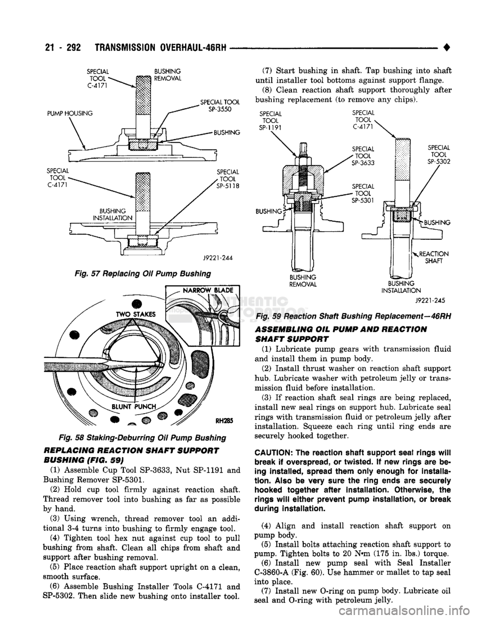
(1) Assemble Cup Tool SP-3633, Nut SP-1191 and
Bushing Remover
SP-5301.
(2) Hold cup tool firmly against reaction shaft.
Thread remover tool into bushing as far as possible
by hand.
(3) Using wrench, thread remover tool an addi
tional 3-4 turns into bushing to firmly engage tool.
(4) Tighten tool hex nut against cup tool to pull
bushing from shaft. Clean all chips from shaft and support after bushing removal.
(5) Place reaction shaft support upright on a clean,
smooth surface.
(6) Assemble Bushing Installer Tools C-4171 and
SP-5302. Then slide new bushing onto installer tool. (7) Start bushing in shaft. Tap bushing into shaft
until installer tool bottoms against support flange. (8) Clean reaction shaft support thoroughly after
bushing replacement (to remove any chips).
SPECIAL
TOOL
SP-1191
SPECIAL
TOOL
C-4171
SPECIAL
TOOL
SP-5302
BUSHING BUSHING
X
REACTION SHAFT
BUSHING
REMOVAL BUSHING
INSTALLATION
J9221-245
Fig. 59 Reaction Shaft Bushing Replacement—46RH
ASSEMBLING
OIL
PUMP
AND
REACTION SHAFT SUPPORT
(1) Lubricate pump gears with transmission fluid
and install them in pump body.
(2) Install thrust washer on reaction shaft support
hub.
Lubricate washer with petroleum jelly or trans mission fluid before installation.
(3) If reaction shaft seal rings are being replaced,
install new seal rings on support hub. Lubricate seal
rings with transmission fluid or petroleum jelly after installation. Squeeze each ring until ring ends are
securely hooked together.
CAUTION:
The
reaction shaft support seal
rings
will
break
if
overspread,
or
twisted.
If new
rings
are be
ing
installed,
spread them only enough
for
installa
tion.
Also
be
very sure
the
ring ends
are
securely
hooked
together
after
installation. Otherwise,
the
rings
will
either
prevent
pump
installation,
or break
during installation.
(4) Align and install reaction shaft support on
pump body.
(5)
Install bolts attaching reaction shaft support to
pump. Tighten bolts to 20 N»m (175 in. lbs.) torque. (6) Install new pump seal with Seal Installer
C-3860-A (Fig. 60). Use hammer or mallet to tap seal
into place.
(7) Install new O-ring on pump body. Lubricate oil
seal and O-ring with petroleum jelly.
Page 1311 of 1502
21
- 310
TRANSMISSION 0VERHAUL-46RH
• plate carefully. Be sure all fluid passages are clean
and clear. Check condition of the upper housing and
transfer plate check balls as well. The check balls and ball seats must not be worn or damaged.
Trial fit each valve and plug in its bore to check
freedom of operation. When clean and dry, the valves and plugs should drop freely into the bores.
Valve body bores do not change dimensionally with
use.
If the valve body functioned correctly when new,
it will continue to operate properly after cleaning
and inspection. It should not be necessary to replace
a valve body assembly unless it is damaged in han
dling.
VALWE
BODY BEASSEMBLY
CAUTION; Do not
force valves
or
plugs
into place
during reassembly.
If the
valve body bores, valves
and
plugs
are
free
of
distortion
or
burrs,
the
valve
body
components should
all
slide into place easily.
In addition,
do not
overtighten
the
transfer
plate
and
valve body screws during reassembly. Over
tightening
can
distort
the
housings
resulting
in
valve sticking,
cross
leakage
and
unsatisfactory
op
eration. Tighten valve body screws
to
recom mended torque only.
Lower Housing Assembly (Fig.
116)
(1) Lubricate valves, springs, and the housing
valve and plug bores with Mopar ATF Plus, or
Dexron II® transmission fluid. (2) Install 3-4 timing valve spring and valve in
lower housing. (3) Install 3-4 shuttle valve in lower housing.
Press valve inward and install E-clip on end of valve
to secure it in housing.
(4) Install 3-4 shuttle valve spring and throttle
plug in housing. (5) Install timing valve end plate. Tighten end
plate screws to 4 N»m (35 in. lbs.) torque.
(6) Install 3-4 shift valve and spring.
(7) Install converter clutch valve, spring and plug.
(8) Install converter clutch timing valve and
spring.
3-4 Accumulator
Assembly
(Fig.
117) (1) Lubricate accumulator piston, seals and hous
ing piston bore with ATF Plus, or Dexron II®. (2) Install new seal rings on accumulator piston.
(3) Install piston and spring in housing.
(4) Install end plate on housing.
Transfer Plate Assembly
(1) Install rear clutch check ball in transfer plate
(Fig. 110). (2) Install filter screen in upper housing separator
plate (Fig. 109). (3) Align and position upper housing separator
plate on transfer plate (Fig. 109).
(4) Install brace plate (Fig. 108). Tighten brace at
taching screws to 4 Nnn (35 in. lbs.) torque. (5) Install remaining separator plate attaching
screws. Tighten screws to 4 N*m (35 in. lbs.) torque.
Page 1313 of 1502
21
- 312 TRANSMISSION OWERHAUL-46RH
•
Assembling
Upper
And
Lower
Housings
(1) Position upper housing so internal passages
and check ball seats are facing upward. Then install
check balls in housing (Fig. 111). Seven check balls are used. The single large check ball is approxi
mately 8.7 mm (11/32 in.) diameter. The remaining 6
check balls are approximately 6.3 mm (1/4 in.) in di ameter.
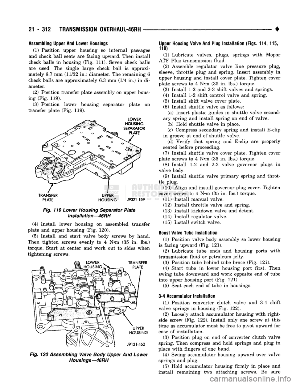
(2) Position transfer plate assembly on upper hous
ing (Fig. 119).
(3) Position lower housing separator plate on
transfer plate (Fig. 119).
TRANSFER
UPPER PLATE HOUSING
J932M59
Fig. 119 Lower Housing Separator Plate Installation—46RH
(4) Install lower housing on assembled transfer
plate and upper housing (Fig. 120).
(5)
Install and start valve body screws by hand.
Then tighten screws evenly to 4 N*m (35 in. lbs.)
torque. Start at center and work out to sides when
tightening screws. Fig. 120 Assembling Valve Body Upper And Lower
Housings—46RH
Upper
Housing
Valve
And
Plug
Installation
(Figs.
114,111,
118)
(1) Lubricate valves, plugs, springs with Mopar
ATF Plus transmission fluid.
(2) Assemble regulator
valve
line pressure plug,
sleeve, throttle plug and spring. Insert assembly in
upper housing and install cover plate. Tighten cover
plate screws to 4 N»m (35 in. lbs.) torque.
(3) Install 1-2 and 2-3 shift valves and springs.
(4) Install 1-2 shift control valve and spring.
(5) Install shift valve cover plate. (6) Install shuttle valve as follows: (a) Insert plastic guides in shuttle valve second
ary spring and install spring on end of valve.
(b) Hold shuttle valve in place.
(c) Compress secondary spring and install E-clip
in groove at end of shuttle valve. (d) Verify that spring and E-clip are properly
seated before proceeding. (7) Install shuttle valve cover plate. Tighten cover
plate screws to 4 N®m (35 in. lbs.) torque.
(8) Install 1-2 and 2-3 valve governor plugs in
valve body. (9) Install shuttle valve primary spring and throt
tle plug. (10) Align and install governor plug cover. Tighten
cover screws to 4 N#m (35 in. lbs.) torque.
(11) Install manual valve.
(12) Install throttle valve and spring.
(13) Install kickdown valve, and detent. (14) Install regulator valve.
(15) Install switch valve.
Boost
Valve
Tube
Installation
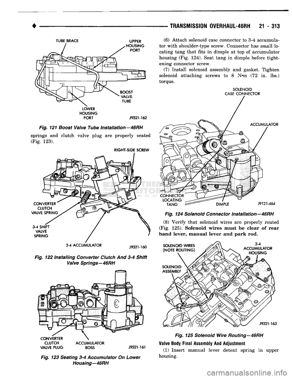
(1) Position valve body assembly so lower housing
is facing upward (Fig. 121). (2) Lubricate tube ends and housing ports with
transmission fluid or petroleum jelly.
(3) Position tube behind tube brace (Fig. 121).
(4) Start tube in lower housing port first. Then
swing tube downward and work opposite end of tube
into upper housing port (Fig. 121).
(5) Seat each end of tube in housings.
3-4 Accumulator
Installation
(1) Position converter clutch valve and 3-4 shift
valve springs in housing (Fig. 122). (2) Loosely attach accumulator housing with right-
side screw (Fig. 122). Install only one screw at this
time as accumulator must be free to pivot upward for ease of installation.
(3) Position plug on end of converter clutch valve
spring. Then compress and hold springs and plug in
place with fingers of one hand.
(4) Swing accumulator housing upward over valve
springs and plug.
(5) Hold accumulator housing firmly in place and
install remaining two attaching screws. Be sure
Page 1314 of 1502
•
TRANSMISSION
OVERHAUL-46RH
21 - 313
TUBE
BRACE
UPPER
LOWER
HOUSING PORT
J932M62
Fig.
121
Boost
Valve
Tube Installation—46RH
springs and clutch valve plug are properly seated (Fig. 123).
RIGHT-SIDE
SCREW
3-4 ACCUMULATOR
Fig.
122 Installing Converter
Clutch
And 3-4 Shift
Valve
Springs—46RH
CLUTCH ACCUMULATOR
VALVE PLUG
BOSS
J9321-161
Fig.
123 Seating 3-4
Accumulator
On
Lower
Housing—46RH
(6) Attach solenoid case connector to 3-4 accumula
tor with shoulder-type screw. Connector has small lo
cating tang that fits in dimple at top of accumulator
housing (Fig. 124). Seat tang in dimple before tight ening connector screw.
(7) Install solenoid assembly and gasket. Tighten
solenoid attaching screws to 8 N*m (72 in. lbs.)
torque.
SOLENOID
CASE
CONNECTOR
Fig.
124
Solenoid
Connector
Installation—46RH
(8) Verify that solenoid wires are properly routed
(Fig. 125). Solenoid wires must be clear of rear
band lever, manual lever and park rod.
Fig.
125
Solenoid
Wire
Routing—46RH
Valve
Body
Final
Assembly
And
Adjustment
(1) Insert manual lever detent spring in upper
housing.
Page 1315 of 1502
21
- 314
TRANSMISSION
OVERHAUL-46RH
—
•
Fig.
126 Manual And
Throttle
Lever
Alignment
If adjustment is required, turn the adjusting screw
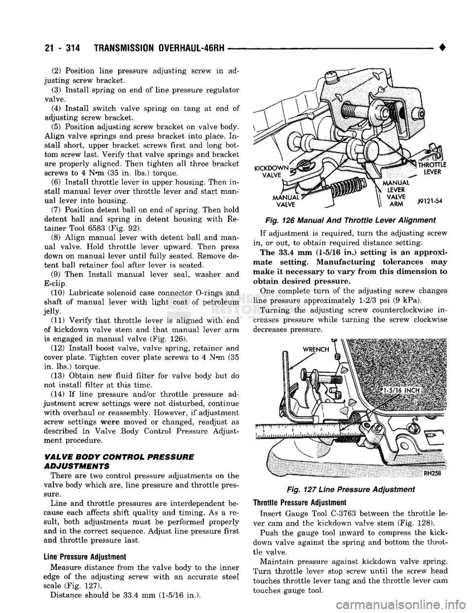
in, or out, to obtain required distance setting. The 33.4 mm (1-5/16 in.) setting is an approxi
mate setting. Manufacturing tolerances may
make it necessary to vary from this dimension to obtain desired pressure.
One complete turn of the adjusting screw changes
line pressure approximately 1-2/3 psi (9 kPa). Turning the adjusting screw counterclockwise in
creases pressure while turning the screw clockwise
decreases pressure.
Fig.
127
Line
Pressure
Adjustment
Throttle
Pressure
Adjustment Insert Gauge Tool C-3763 between the throttle le
ver cam and the kickdown valve stem (Fig. 128).
Push the gauge tool inward to compress the kick-
down valve against the spring and bottom the throt
tle valve.
Maintain pressure against kickdown valve spring.
Turn throttle lever stop screw until the screw head
touches throttle lever tang and the throttle lever cam
touches gauge tool.
(2) Position line pressure adjusting screw in ad
justing screw bracket.
(3) Install spring on end of line pressure regulator
valve. (4) Install switch valve spring on tang at end of
adjusting screw bracket. (5) Position adjusting screw bracket on valve body.
Align valve springs and press bracket into place. In stall short, upper bracket screws first and long bot
tom screw last. Verify that valve springs and bracket are properly aligned. Then tighten all three bracket
screws to 4 N*m (35 in. lbs.) torque.
(6) Install throttle lever in upper housing. Then in
stall manual lever over throttle lever and start man
ual lever into housing.
(7) Position detent ball on end of spring. Then hold
detent ball and spring in detent housing with Re
tainer Tool 6583 (Fig. 92). (8) Align manual lever with detent ball and man
ual valve. Hold throttle lever upward. Then press
down on manual lever until fully seated. Remove de
tent ball retainer fool after lever is seated.
(9) Then Install manual lever seal, washer and
E-clip.
(10) Lubricate solenoid case connector O-rings and
shaft of manual lever with light coat of petroleum
jelly. (11) Verify that throttle lever is aligned with end
of kickdown valve stem and that manual lever arm
is engaged in manual valve (Fig. 126).
(12) Install boost valve, valve spring, retainer and
cover plate. Tighten cover plate screws to 4 N»m (35
in. lbs.) torque.
(13) Obtain new fluid filter for valve body but do
not install filter at this time.
(14) If line pressure and/or throttle pressure ad
justment screw settings were not disturbed, continue with overhaul or reassembly. However, if adjustment screw settings were moved or changed, readjust as
described in Valve Body Control Pressure Adjust
ment procedure.
VALVE
BODY
CONTROL
PRESSURE
ADJUSTMENTS
There are two control pressure adjustments on the
valve body which are, line pressure and throttle pres
sure.
Line and throttle pressures are interdependent be
cause each affects shift quality and timing. As a re
sult, both adjustments must be performed properly and in the correct sequence. Adjust line pressure first
and throttle pressure last.
Line
Pressure
Adjustment Measure distance from the valve body to the inner
edge of the adjusting screw with an accurate steel scale (Fig. 127). Distance should be 33.4 mm (1-5/16 in.).