1993 DODGE TRUCK torque
[x] Cancel search: torquePage 1183 of 1502
21
- 182
TRANSMISSION OVERHAUL—32RH
• VAL VE
BODY
ASSEMBL
Y
CAUTION:
Do not
force
the valves or plugs
into
place
during
reassembly. If the valve body
bores,
valves
and plugs are
free
of
distortion
or burrs, the
valve body components should all slide
into
place
easily. In
addition,
do not
overtighten
the
transfer
plate
and valve body
screws
during
reassembly.
Overtightening
can
distort
the valve body
resulting
in valve sticking,
cross
leakage and
unsatisfactory
operation. Tighten valve body
screws
to recom mended
torque
only.
(1) Lubricate valve body bores, valves and plugs
with transmission fluid.
(2) Insert rear clutch and rear servo check balls in
transfer plate (Fig. 100).
(3) Install filter screen in separator plate (Fig.
100).
(4) Align and install separator plate on transfer
plate. Verify check ball position before installing sep arator plate on transfer plate.
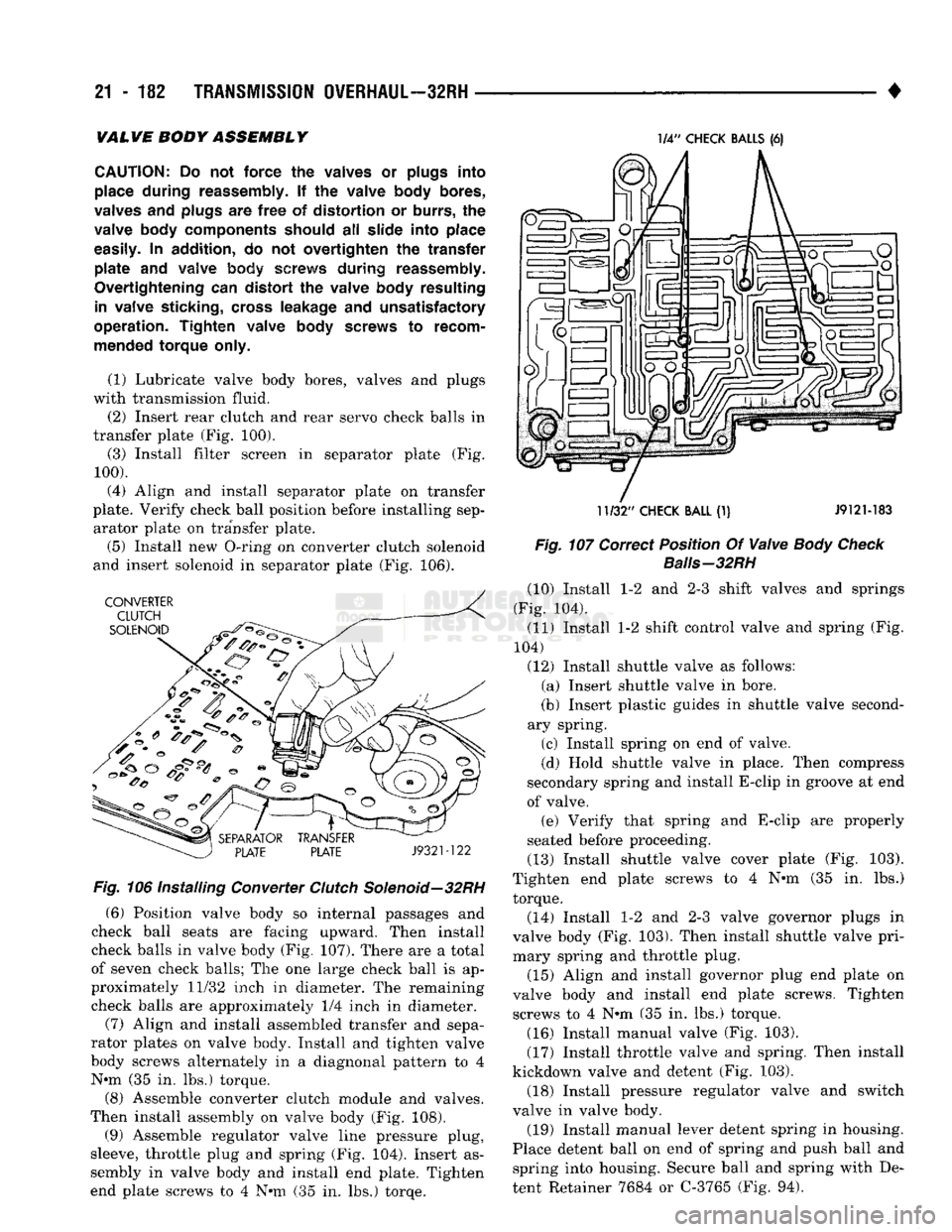
(5) Install new O-ring on converter clutch solenoid
and insert solenoid in separator plate (Fig. 106). Fig. 106
Installing
Converter
Clutch
Solenoid—32RH
(6) Position valve body so internal passages and
check ball seats are facing upward. Then install
check balls in valve body (Fig. 107). There are a total
of seven check balls; The one large check ball is ap
proximately 11/32 inch in diameter. The remaining
check balls are approximately 1/4 inch in diameter.
(7) Align and install assembled transfer and sepa
rator plates on valve body. Install and tighten valve
body screws alternately in a diagnonal pattern to 4 N»m (35 in. lbs.) torque.
(8) Assemble converter clutch module and valves.
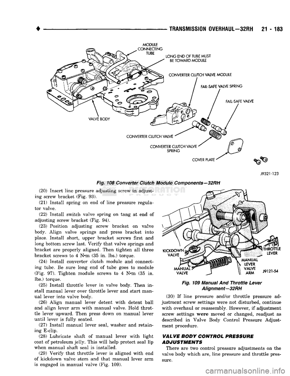
Then install assembly on valve body (Fig. 108).
(9) Assemble regulator valve line pressure plug,
sleeve, throttle plug and spring (Fig. 104). Insert as
sembly in valve body and install end plate. Tighten
end plate screws to 4 N»m (35 in. lbs.) torqe. 1/4"
CHECK
BALLS
(6)
11/32"
CHECK
BALL
(1) J912M83
Fig. 107
Correct
Position
Of
Valve
Body Check
Baiis-32RH
(10) Install 1-2 and 2-3 shift valves and springs
(Fig. 104).
(11) Install 1-2 shift control valve and spring (Fig.
104)
(12) Install shuttle valve as follows: (a) Insert shuttle valve in bore.
(b) Insert plastic guides in shuttle valve second
ary spring.
(c) Install spring on end of valve.
(d) Hold shuttle valve in place. Then compress
secondary spring and install E-clip in groove at end
of valve. (e) Verify that spring and E-clip are properly
seated before proceeding.
(13) Install shuttle valve cover plate (Fig. 103).
Tighten end plate screws to 4 N»m (35 in. lbs.)
torque.
(14) Install 1-2 and 2-3 valve governor plugs in
valve body (Fig. 103). Then install shuttle valve pri
mary spring and throttle plug.
(15) Align and install governor plug end plate on
valve body and install end plate screws. Tighten screws to 4 N*m (35 in. lbs.) torque.
(16) Install manual valve (Fig. 103).
(17) Install throttle valve and spring. Then install
kickdown valve and detent (Fig. 103).
(18) Install pressure regulator valve and switch
valve in valve body.
(19) Install manual lever detent spring in housing.
Place detent ball on end of spring and push ball and spring into housing. Secure ball and spring with De
tent Retainer 7684 or C-3765 (Fig. 94).
Page 1184 of 1502
•
TRANSMISSION
OVERHAUL—32RH
21 - 183
MODULE
J932M23
Fig.
108 Converter
Clutch
Module
Components—32RH
(20) Insert line pressure adjusting screw in adjust
ing screw bracket (Fig. 93).
(21) Install spring on end of line pressure regula
tor valve.
(22) Install switch valve spring on tang at end of
adjusting screw bracket (Fig. 94).
(23) Position adjusting screw bracket on valve
body. Align valve springs and press bracket into
place. Install short, upper bracket screws first and long bottom screw last. Verify that valve springs and
bracket are properly aligned. Then tighten all three
bracket screws to 4 N*m (35 in. lbs.) torque.
(24) Install converter clutch module and connect
ing tube. Be sure long end of tube goes to module (Fig. 97). Tighten module screws to 4 Nrn (35 in.
lbs.) torque.
(25) Install throttle lever in valve body. Then in
stall manual lever over throttle lever and start man
ual lever into valve body. (26) Align manual lever detent with detent ball
and align lever arm with manual valve. Hold throt
tle lever upward. Then press down on manual lever
until lever is fully seated. (27) Install manual lever seal, washer and retain
ing E-clip. (28) Lubricate shaft of manual lever with light
coat of petroleum jelly. This will help protect seal lip
when manual shaft seal is installed. (29) Verify that throttle lever is aligned with end
of kickdown valve stem and that manual lever arm
is engaged in manual valve (Fig. 109).
Fig.
109 Manual And
Throttle
Lever
Alignment—32RH
(30) If line pressure and/or throttle pressure ad
justment screw settings were not disturbed, continue with overhaul or reassembly. However, if adjustment screw settings were moved or changed, readjust as
described in Valve Body Control Pressure Adjust
ment procedure.
VALVE BODY CONTROL PRESSURE
ADJUSTMENTS
There are two control pressure adjustments on the
valve body which are, line pressure and throttle pres
sure.
Page 1186 of 1502
•
TRANSMISSION
OVERHAUL—32RH
21-185
(3) Examine bolt holes in overrunning clutch cam.
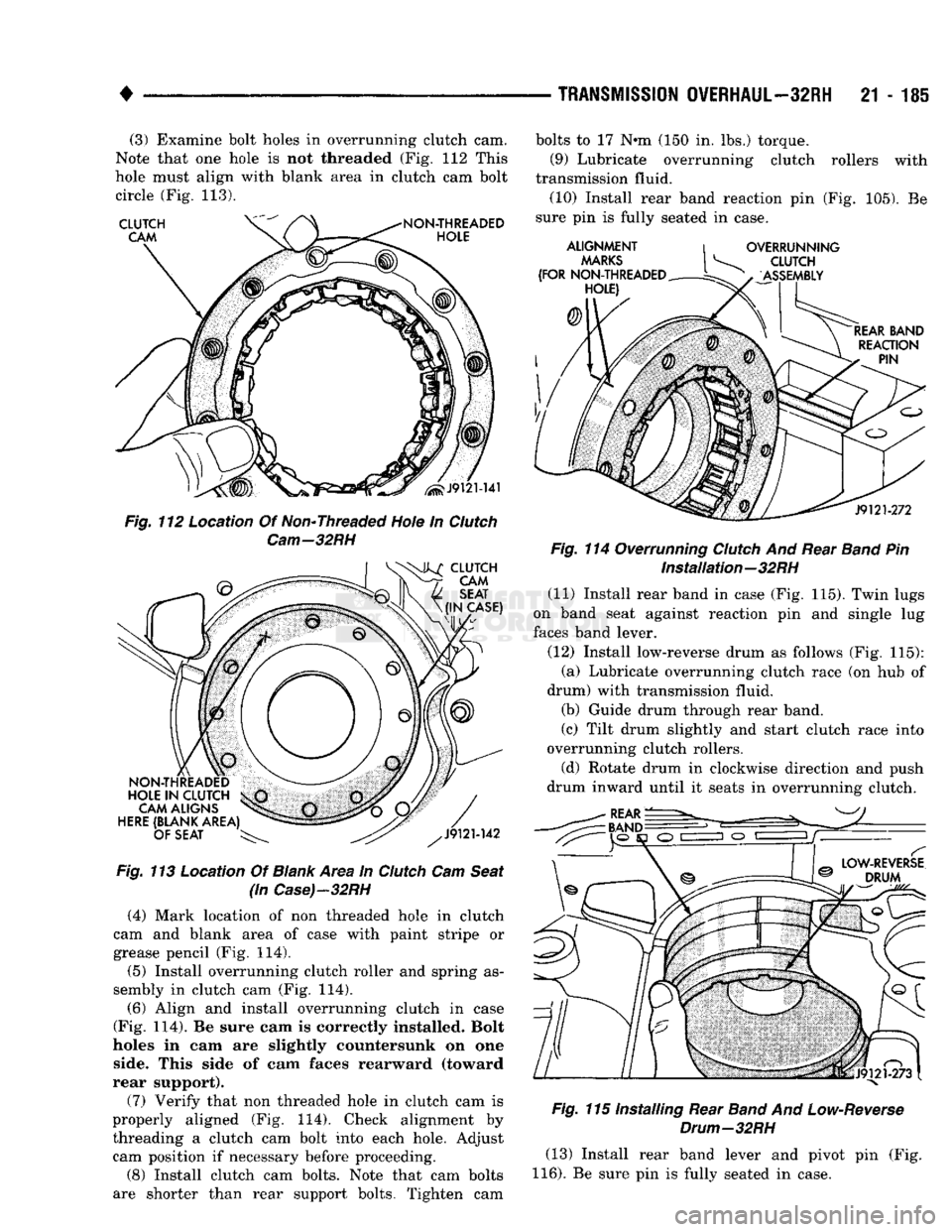
Note that one hole is not threaded (Fig. 112 This
hole must align with blank area in clutch cam bolt circle (Fig. 113).
Fig.
113 Location Of
Blank
Area in
Clutch
Cam
Seat
(in
Case)-32RH
(4) Mark location of non threaded hole in clutch
cam and blank area of case with paint stripe or
grease pencil (Fig. 114).
(5) Install overrunning clutch roller and spring as
sembly in clutch cam (Fig. 114).
(6) Align and install overrunning clutch in case
(Fig. 114). Be sure cam is correctly installed. Bolt
holes in cam are slightly countersunk on one side. This side of cam faces rearward (toward
rear support).
(7) Verify that non threaded hole in clutch cam is
properly aligned (Fig. 114). Check alignment by threading a clutch cam bolt into each hole. Adjust cam position if necessary before proceeding.
(8) Install clutch cam bolts. Note that cam bolts
are shorter than rear support bolts. Tighten cam bolts to 17 N»m (150 in. lbs.) torque.
(9) Lubricate overrunning clutch rollers with
transmission fluid. (10) Install rear band reaction pin (Fig. 105). Be
sure pin is fully seated in case.
Fig.
114 Overrunning
Clutch
And Rear
Band
Pin Installation—32RH
(11) Install rear band in case (Fig. 115). Twin lugs
on band seat against reaction pin and single lug
faces band lever.
(12) Install low-reverse drum as follows (Fig. 115): (a) Lubricate overrunning clutch race (on hub of
drum) with transmission fluid. (b) Guide drum through rear band.
(c) Tilt drum slightly and start clutch race into
overrunning clutch rollers.
(d) Rotate drum in clockwise direction and push
drum inward until it seats in overrunning clutch.
Fig.
115 Installing Rear
Band
And
Low-Reverse
Drum—32RH
(13) Install rear band lever and pivot pin (Fig.
116).
Be sure pin is fully seated in case.
Page 1187 of 1502
21
- 186
TRANSMISSION
OVERHAUL—32RH
Fig.
116 Installing Rear
Band
Lever
And Pivot
Pin-32RH
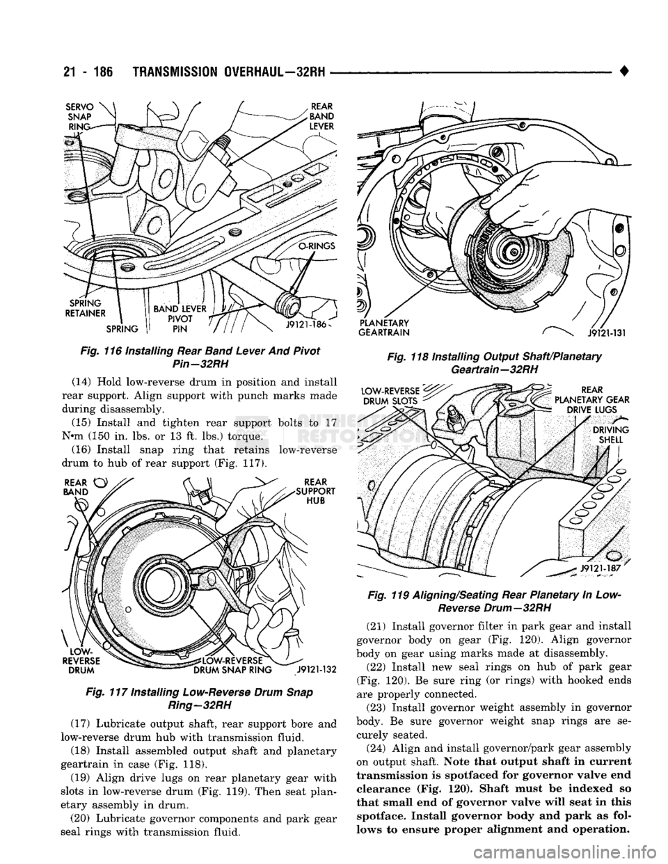
(14) Hold low-reverse drum in position and install
rear support. Align support with punch marks made
during disassembly.
(15) Install and tighten rear support bolts to 17
N*m (150 in. lbs. or 13 ft. lbs.) torque.
(16) Install snap ring that retains low-reverse
drum to hub of rear support (Fig. 117).
Fig.
117 Installing
Low-Reverse
Drum
Snap
Ring—32RH
(17) Lubricate output shaft, rear support bore and
low-reverse drum hub with transmission fluid. (18) Install assembled output shaft and planetary
geartrain in case (Fig. 118).
(19) Align drive lugs on rear planetary gear with
slots in low-reverse drum (Fig. 119). Then seat plan
etary assembly in drum.
(20) Lubricate governor components and park gear
seal rings with transmission fluid. •
Fig.
118 Installing Output Shaft/Planetary Geartrain—32RH
Fig.
119
Aligning/Seating
Rear Planetary In Low-
Reverse
Drum—32RH
(21) Install governor filter in park gear and install
governor body on gear (Fig. 120). Align governor
body on gear using marks made at disassembly.
(22) Install new seal rings on hub of park gear
(Fig. 120). Be sure ring (or rings) with hooked ends
are properly connected.
(23) Install governor weight assembly in governor
body. Be sure governor weight snap rings are se curely seated.
(24) Align and install governor/park gear assembly
on output shaft. Note that output shaft in current
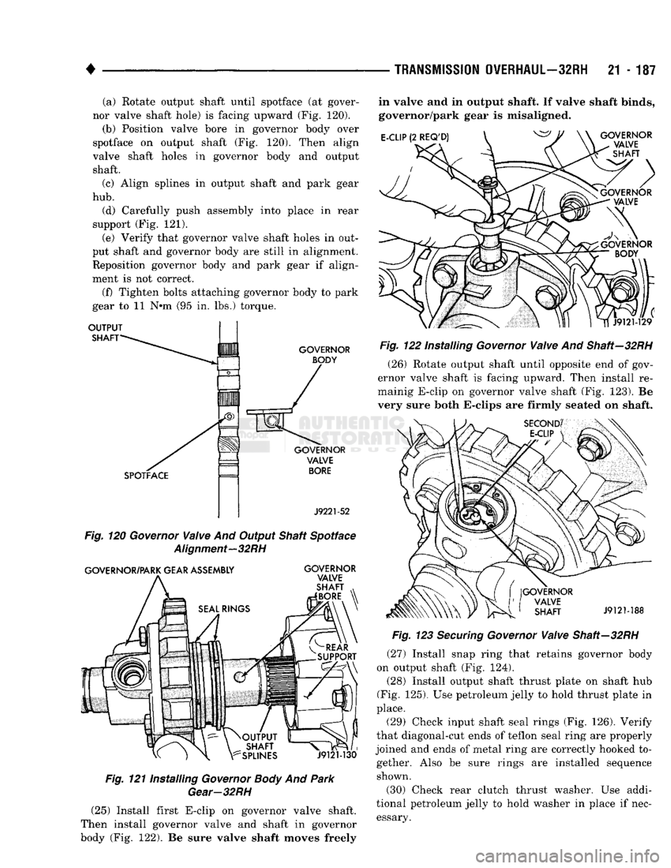
transmission is spotfaced for governor valve end clearance (Fig. 120). Shaft must be indexed so
that small end of governor valve will seat in this spotface. Install governor body and park as fol
lows to ensure proper alignment and operation.
Page 1188 of 1502
•
TRANSMISSION
OVERHAUL—32RH
21 - 187 (a) Rotate output shaft until spotface (at gover
nor valve shaft hole) is facing upward (Fig. 120). (b) Position valve bore in governor body over
spotface on output shaft (Fig. 120). Then align
valve shaft holes in governor body and output shaft.
(c) Align splines in output shaft and park gear
hub.
(d) Carefully push assembly into place in rear
support (Fig. 121). (e) Verify that governor valve shaft holes in out
put shaft and governor body are still in alignment.
Reposition governor body and park gear if align
ment is not correct.
(f) Tighten bolts attaching governor body to park
gear to 11 N*m (95 in. lbs.) torque.
OUTPUT
SHAFT
GOVERNOR BODY
GOVERNOR VALVE
BORE
J9221-52
Fig.
120
Governor
Valve
And Output Shaft Spotface
Alignment—32RH
GOVERNOR/PARK GEAR ASSEMBLY GOVERNOR
VALVE
SHAFT
BORE
J9121-130
Fig.
121 Installing
Governor
Body
And
Park
Gear-32RH
in valve and in output shaft. If valve shaft binds,
governor/park gear is misaligned.
E-CLIP
(2
REQ'D)
GOVERNOR
VALVE
\-
SHAFT
Fig.
122 Installing
Governor
Valve
And Shaft—32RH (26) Rotate output shaft until opposite end of gov
ernor valve shaft is facing upward. Then install re-
mainig E-clip on governor valve shaft (Fig. 123). Be
very sure both E-clips are firmly seated on shaft.
GOVERNOR VALVE SHAFT
J9121-188
Fig.
123
Securing
Governor
Valve
Shaft—32RH
(27) Install snap ring that retains governor body
on output shaft (Fig. 124).
(28) Install output shaft thrust plate on shaft hub
(Fig.
125).
Use petroleum jelly to hold thrust plate in
place.
(29) Check input shaft seal rings (Fig. 126). Verify
that diagonal-cut ends of teflon seal ring are properly
joined and ends of metal ring are correctly hooked to gether. Also be sure rings are installed sequence shown.
(30) Check rear clutch thrust washer. Use addi
tional petroleum jelly to hold washer in place if nec essary. (25) Install first E-clip on governor valve shaft.
Then install governor valve and shaft in governor
body (Fig. 122). Be sure valve shaft moves freely
Page 1192 of 1502
•
Fig. 138 installing Accumulator Piston And Spring—32RH
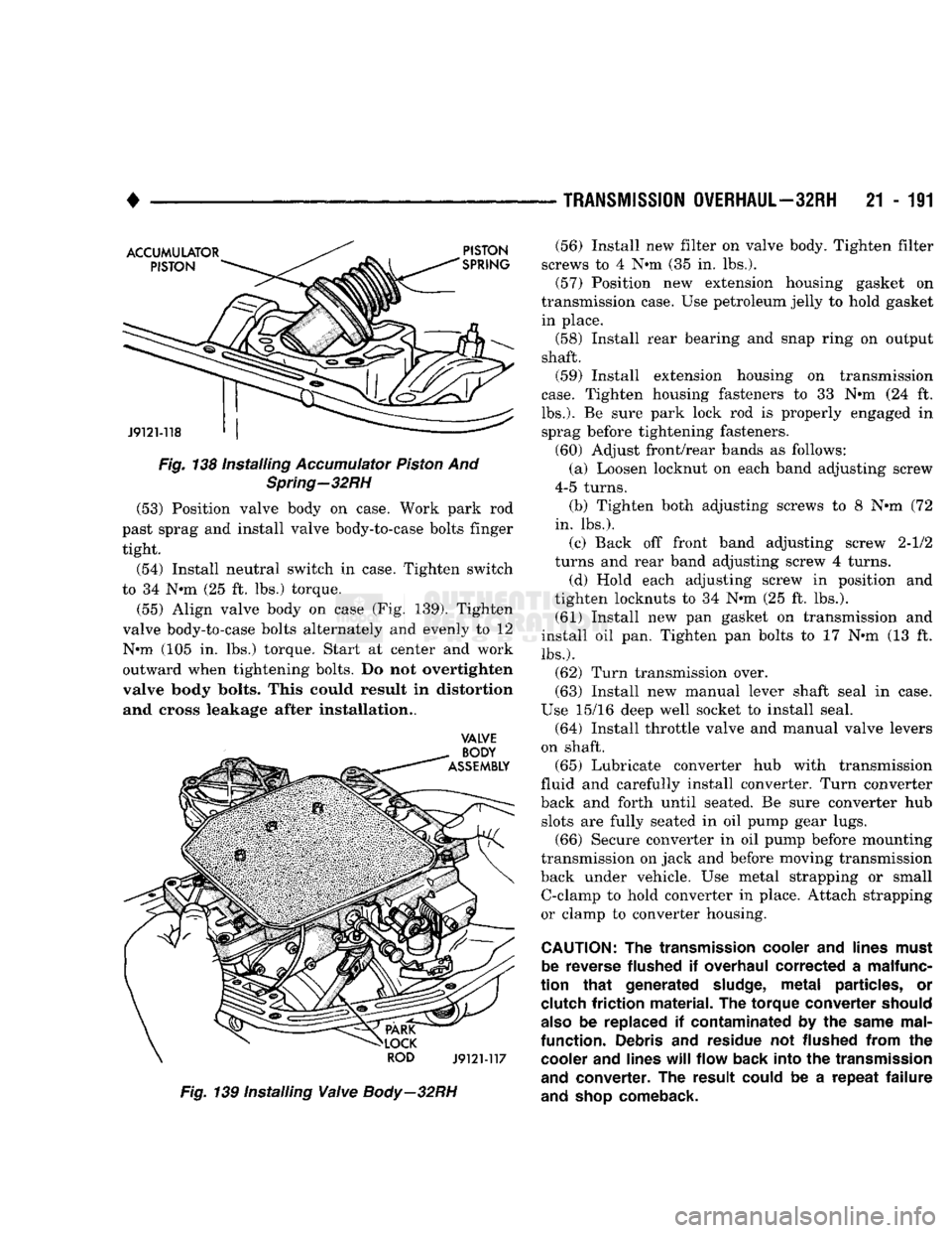
(53) Position valve body on case. Work park rod
past sprag and install valve body-to-case bolts finger tight.
(54) Install neutral switch in case. Tighten switch
to 34 N-m (25 ft. lbs.) torque.
(55) Align valve body on case (Fig. 139). Tighten
valve body-to-case bolts alternately and evenly to 12
N»m (105 in. lbs.) torque. Start at center and work
outward when tightening bolts. Do not overtighten
valve body bolts. This could result in distortion and cross leakage after Installation..
VALVE
Fig. 139 Installing
Valve
Body—32RH
—
TRANSMISSION
OVERHAUL—32RH
21 - 1S1 (56) Install new filter on valve body. Tighten filter
screws to 4 N»m (35 in. lbs.).
(57) Position new extension housing gasket on
transmission case. Use petroleum jelly to hold gasket in place.
(58) Install rear bearing and snap ring on output
shaft. (59) Install extension housing on transmission
case. Tighten housing fasteners to 33 N»m (24 ft.
lbs.).
Be sure park lock rod is properly engaged in sprag before tightening fasteners.
(60) Adjust front/rear bands as follows: (a) Loosen locknut on each band adjusting screw
4-5 turns.
(b) Tighten both adjusting screws to 8 N*m (72
in.
lbs.).
(c) Back off front band adjusting screw 2-1/2
turns and rear band adjusting screw 4 turns.
(d) Hold each adjusting screw in position and
tighten locknuts to 34 N*m (25 ft. lbs.).
(61) Install new pan gasket on transmission and
install oil pan. Tighten pan bolts to 17 N«m (13 ft.
lbs.).
(62) Turn transmission over.
(63) Install new manual lever shaft seal in case.
Use 15/16 deep well socket to install seal.
(64) Install throttle valve and manual valve levers
on shaft. (65) Lubricate converter hub with transmission
fluid and carefully install converter. Turn converter
back and forth until seated. Be sure converter hub slots are fully seated in oil pump gear lugs.
(66) Secure converter in oil pump before mounting
transmission on jack and before moving transmission
back under vehicle. Use metal strapping or small C-clamp to hold converter in place. Attach strapping
or clamp to converter housing.
CAUTION:
The
transmission
cooler
and
lines
must
be
reverse
flushed
if
overhaul
corrected
a
malfunc
tion that
generated
sludge,
metal
particles,
or
clutch
friction
material.
The
torque
converter
should
also
be
replaced
if
contaminated
by the
same
mal
function.
Debris
and
residue
not
flushed
from
the
cooler
and
lines
will
flow
back
into the
transmission
and
converter.
The
result
could
be a
repeat
failure
and
shop
comeback.
Page 1207 of 1502
21
- 206
TRANSMISSION
OVERHAUL—36RH/37RH
•
PULLER
BOLT
SP-3701
ADAPTER
J9121-58
Fig.
54
Assembling
Clutch
Cam Puller
Bolt
And
Press
Piate-36RH/37RH
BE
SURE
PLATE
IS
SEATED
SQUARELY
ON
CAM
J9121-59
Fig.
55
Positioning
Puller
Plate
On
Clutch
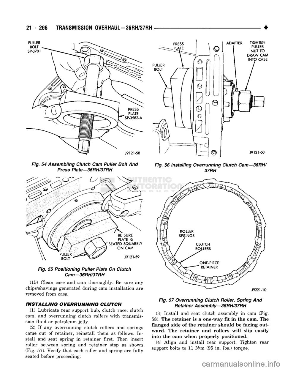
Cam-36RH/37RH (15) Clean case and cam thoroughly. Be sure any
chips/shavings generated during cam installation are
removed from case.
INSTALLING
OVERRUNNING
CLUTCH
(1) Lubricate rear support hub, clutch race, clutch
cam, and overrunning clutch rollers with transmis
sion fluid or petroleum jelly.
(2) If any overrunning clutch rollers and springs
came out of retainer, reinstall them as follows: In stall and seat spring in retainer first. Then insert
roller between spring and retainer stop as shown (Fig. 57). Verify that each roller and spring are fully
seated before proceeding.
TIGHTEN
PULLER
NUT TO
DRAW
CAM
INTO
CASE
J9121-60
Fig.
56 Installing Overrunning
Clutch
Cam—36RH/
37RH
J922M0
Fig.
57 Overrunning
Clutch
Roller,
Spring
And Retainer
Assembly—36RH/37RH
(3) Install and seat clutch assembly in cam (Fig.
58).
The retainer is a one-way fit in the cam. The
flanged side of the retainer should be facing out ward. The retainer and rollers will slip easily
into the cam when properly positioned.
(4) Align and install rear support. Tighten rear
support bolts to 11 N#m (95 in. lbs.) torque.
Page 1211 of 1502
21
- 210
TRANSMISSION
OVERHAUL-36RH/37RH
•
SPECIAL
TOOL
C-4171
BUSHING
m
REMOVAL
PUMP
HOUSING
SPECIAL
TOOL
C-4171
SPECIAL
TOOL
SP-3550
BUSHING
SPECIAL
TOOL
SP-5118
J9221-244
Fig.
64 Oil
Pump Bushing
Replacement—36RH/
37RH
mm
Fig.
65 Staking And Deburring Oil
Pump Bushing
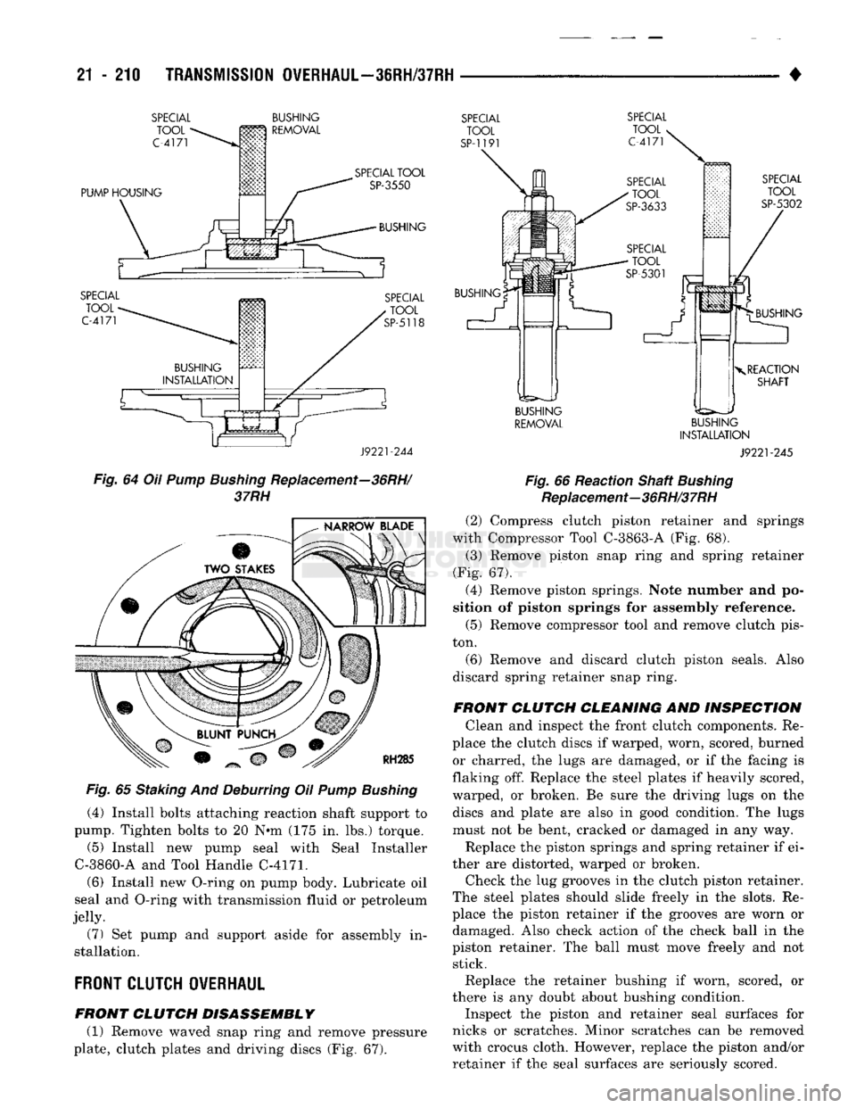
(4) Install bolts attaching reaction shaft support to
pump. Tighten bolts to 20 N«m (175 in. lbs.) torque.
(5) Install new pump seal with Seal Installer
C-3860-A and Tool Handle C-4171.
(6) Install new O-ring on pump body. Lubricate oil
seal and O-ring with transmission fluid or petroleum
jelly.
(7) Set pump and support aside for assembly in
stallation.
FRONT
CLUTCH OVERHAUL
FRONT CLUTCH DISASSEMBLY (1) Remove waved snap ring and remove pressure
plate, clutch plates and driving discs (Fig. 67).
SPECIAL
TOOL
SP-119
SPECIAL
TOOL
C-4171
SPECIAL
TOOL
SP-5302
BUSHING BUSHING
X
REACTION
SHAFT
BUSHING
REMOVAL
BUSHING
INSTALLATION
J9221-245
Fig.
66 Reaction Shaft
Bushing
Replacement—36RH/37RH
(2) Compress clutch piston retainer and springs
with Compressor Tool C-3863-A (Fig. 68).
(3) Remove piston snap ring and spring retainer
(Fig. 67).
(4) Remove piston springs. Note number and po
sition of piston springs for assembly reference.
(5) Remove compressor tool and remove clutch pis
ton.
(6) Remove and discard clutch piston seals. Also
discard spring retainer snap ring.
FRONT CLUTCH CLEANING AND INSPECTION Clean and inspect the front clutch components. Re
place the clutch discs if warped, worn, scored, burned or charred, the lugs are damaged, or if the facing is
flaking off. Replace the steel plates if heavily scored,
warped, or broken. Be sure the driving lugs on the discs and plate are also in good condition. The lugs
must not be bent, cracked or damaged in any way.
Replace the piston springs and spring retainer if ei
ther are distorted, warped or broken. Check the lug grooves in the clutch piston retainer.
The steel plates should slide freely in the slots. Re
place the piston retainer if the grooves are worn or damaged. Also check action of the check ball in the
piston retainer. The ball must move freely and not stick.
Replace the retainer bushing if worn, scored, or
there is any doubt about bushing condition.
Inspect the piston and retainer seal surfaces for
nicks or scratches. Minor scratches can be removed
with crocus cloth. However, replace the piston and/or
retainer if the seal surfaces are seriously scored.