1993 DODGE TRUCK torque
[x] Cancel search: torquePage 1317 of 1502
21
- 31S
TRANSMISSION
0VERHAUL-46RH
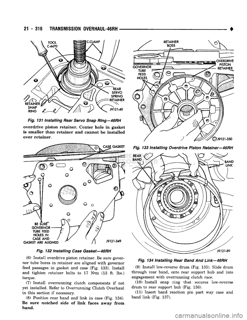
Fig.
131 Installing Rear
Servo
Snap
Ring—46RH
overdrive piston retainer. Center hole in gasket
is smaller than retainer and cannot be installed over retainer.
Fig.
132 Installing
Case
Gasket—46RH
(6) Install overdrive piston retainer. Be sure gover
nor tube bores in retainer are aligned with governor
feed passages in gasket and case (Fig. 133). Install and tighten retainer bolts to 17 N»m (13 ft. lbs.)
torque.
(7) Install overrunning clutch components if not
yet installed. Refer to Overrunning Clutch Overhaul in this section if necessary.
(8) Position rear band and link in case (Fig. 134).
Be sure notched side of link faces away from
band. •
Fig.
133 Installing Overdrive
Piston
Retainer—46RH
Fig.
134 Installing Rear
Band
And
Link—46RH
(9) Install low-reverse drum (Fig. 135). Slide drum
through rear band, onto rear support hub and into engagement with overrunning clutch race.
(10) Install snap ring that secures low-reverse
drum to rear support hub (Fig. 136).
(11) Insert band reaction pin part way case and
band link (Fig. 137).
Page 1318 of 1502
•
Fig.
136 Installing
Low-Reverse
Drum
Snap
Ring-46RH
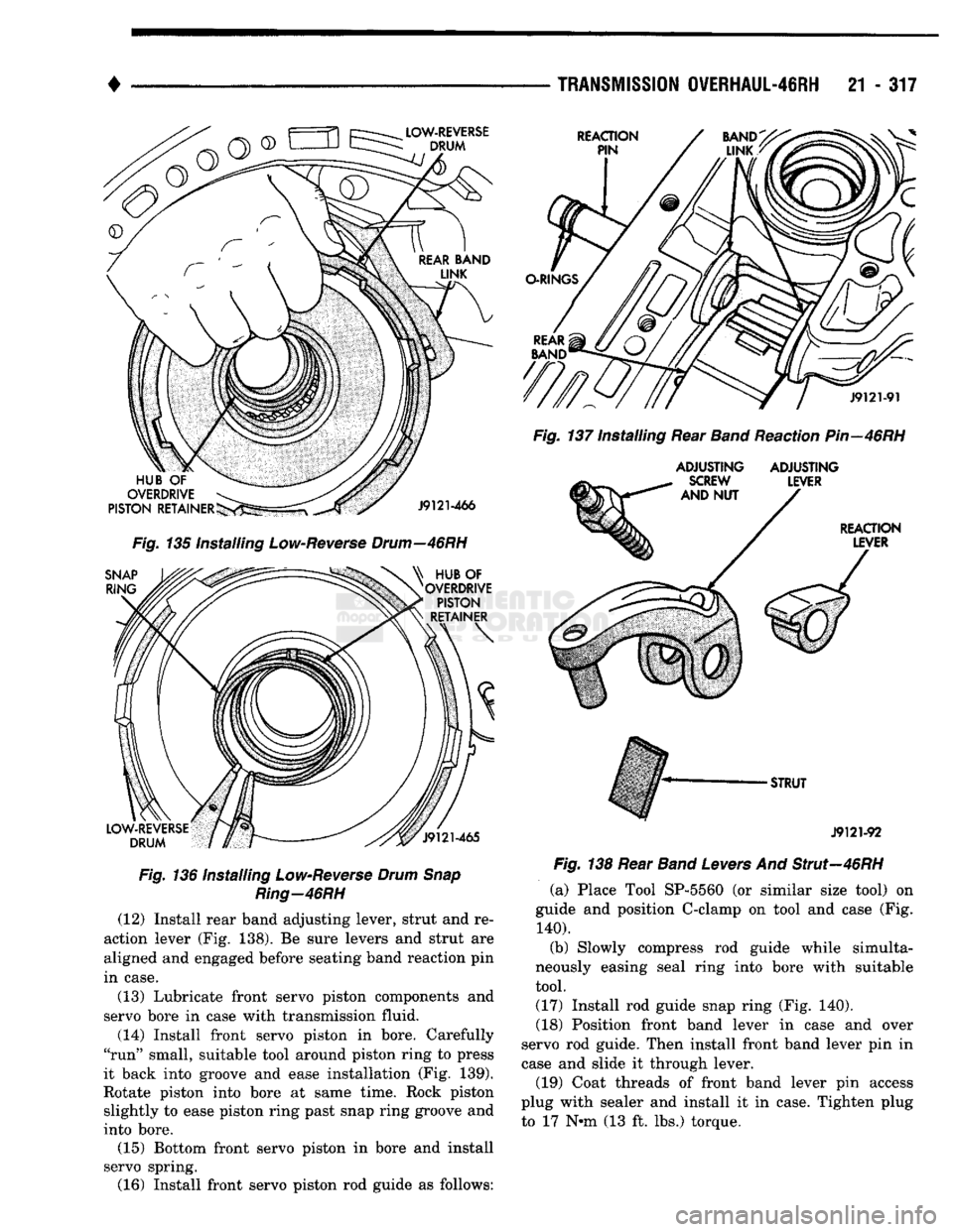
(12) Install rear band adjusting lever, strut and re
action lever (Fig. 138). Be sure levers and strut are
aligned and engaged before seating band reaction pin
in case.
(13) Lubricate front servo piston components and
servo bore in case with transmission fluid.
(14) Install front servo piston in bore. Carefully
"run" small, suitable tool around piston ring to press
it back into groove and ease installation (Fig. 139).
Rotate piston into bore at same time. Rock piston slightly to ease piston ring past snap ring groove and
into bore. (15) Bottom front servo piston in bore and install
servo spring. (16) Install front servo piston rod guide as follows:
TRANSMISSION
0VERHAUL-4SRH
21 - 317
Fig,
137 Installing Rear
Band
Reaction
Pin—46RH
ADJUSTING ADJUSTING
J9121-92
Fig.
138 Rear
Band
Levers
And Strut—46RH (a) Place Tool SP-5560 (or similar size tool) on
guide and position C-clamp on tool and case (Fig.
140).
(b) Slowly compress rod guide while simulta
neously easing seal ring into bore with suitable
tool. (17) Install rod guide snap ring (Fig. 140).
(18) Position front band lever in case and over
servo rod guide. Then install front band lever pin in
case and slide it through lever.
(19) Coat threads of front band lever pin access
plug with sealer and install it in case. Tighten plug to 17 N-m (13 ft. lbs.) torque.
Page 1321 of 1502
21
- 320
TRANSMISSION
0¥ERHAUL-46RH
LEVER
STRUT
J9121-18
Fig.
147 Front
Band
And
Linkage
Installation—46RH
Fig.
148 Installing Oil
Pump
Gasket
And Pilot
Studs-46RH
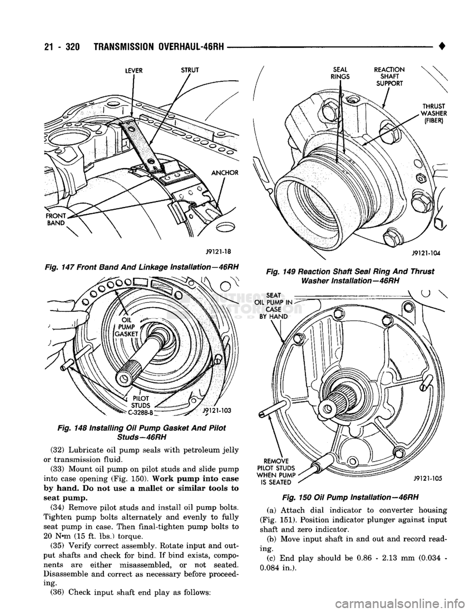
(32) Lubricate oil pump seals with petroleum jelly
or transmission fluid.
(33) Mount oil pump on pilot studs and slide pump
into case opening (Fig. 150). Work pump into case
by hand. Do not use a mallet or similar tools to seat pump.
(34) Remove pilot studs and install oil pump bolts.
Tighten pump bolts alternately and evenly to fully seat pump in case. Then final-tighten pump bolts to 20 N-m (15 ft. lbs.) torque.
(35) Verify correct assembly. Rotate input and out
put shafts and check for bind. If bind exists, compo nents are either misassembled, or not seated.
Disassemble and correct as necessary before proceeding. •
Fig.
149 Reaction Shaft
Seal Ring
And Thrust
Washer
installation—46RH
Fig.
150 Oil
Pump
installation—46RH (a) Attach dial indicator to converter housing
(Fig. 151). Position indicator plunger against input
shaft and zero indicator.
(b) Move input shaft in and out and record read
ing.
(c) End play should be 0.86 - 2.13 mm (0.034 -
0.084 in.). (36) Check input shaft end play as follows:
Page 1323 of 1502

21
- 322
TRANSMISSION
OVERHAUL-46RH
•
J932M33
Fig.
155
Checking
Alignment
Of Overdrive Planetary
Gear
And Overrunning
Clutch
Splines—46RH
(44) Carefully withdraw alignment tool from over
drive unit.
(45) Lubricate intermediate shaft splines and
bushing surfaces with transmission fluid or petro leum jelly.
(46) Install overdrive unit. Be sure governor tubes
are aligned with feed holes in piston retainer boss.
Intermediate shaft is snug fit in overdrive planetary
gear and overrunning clutch. If overdrive unit will
not seat fully, rotate overdrive output shaft slightly
to align splines and try again.
(47) Apply 1-2 drops of Mopar thread adhesive (or
Loctite 242) to overdrive unit attaching bolts. Then
install and tighten bolts to 34 N» (25 ft. lbs.) torque.
(48) Install accumulator inner spring, piston and
outer spring (Fig. 156).
ACCUMULATOR
OUTER
Fig.
156 Installing
Accumulator
Piston
And
Springs
(49) Verify that park/neutral position switch has
not been installed in case. Valve body can not be in stalled if switch is in position.
(50) Install valve body as follows: (a) Start park rod into park pawl. If rod will not
slide past park pawl, pawl is engaged in park gear.
Rotate overdrive output shaft with socket to free
pawl and allow rod to engage. (b) Align and seat valve body on case. Be sure
manual lever shaft and overdrive connector are
fully seated in case.
(c) Install and start all valve body attaching
bolts by hand. Then tighten bolts evenly, in a di agonal pattern to 12 Nnn (105 in. lbs.) torque. Do
not overtighten valve body bolts. This could result in distortion and cross leakage after in stallation..
(51) Install new filter on valve body. Tighten filter
screws to 4 Nnn (35 in. lbs.).
(52) Install seal on park/neutral position switch
(Fig. 157). Then install and tighten switch to 34 Nnn
(25 ft. lbs.).
Fig.
157 Park/Neutral Position
Switch
Seal
Position
(53) Adjust front and rear bands as follows:
(a) Loosen locknut on each band adjusting screw
4-5 turns.
(b) Tighten both adjusting screws to 8 Nnn (72
in. lbs.).
(c) Back off front band adjusting screw 2-1/2
turns.
(d) Back off rear band adjusting screw 2 turns.
(e) Hold each adjusting screw in position and
tighten locknuts to 34 Nnn (25 ft. lbs.) torque.
(54) Install magnet in oil pan. Magnet goes on
small protrusion at corner of pan.
(55) Position new oil pan gasket on case and in
stall oil pan. Tighten pan bolts to 17 Nnn (13 ft. lbs.).
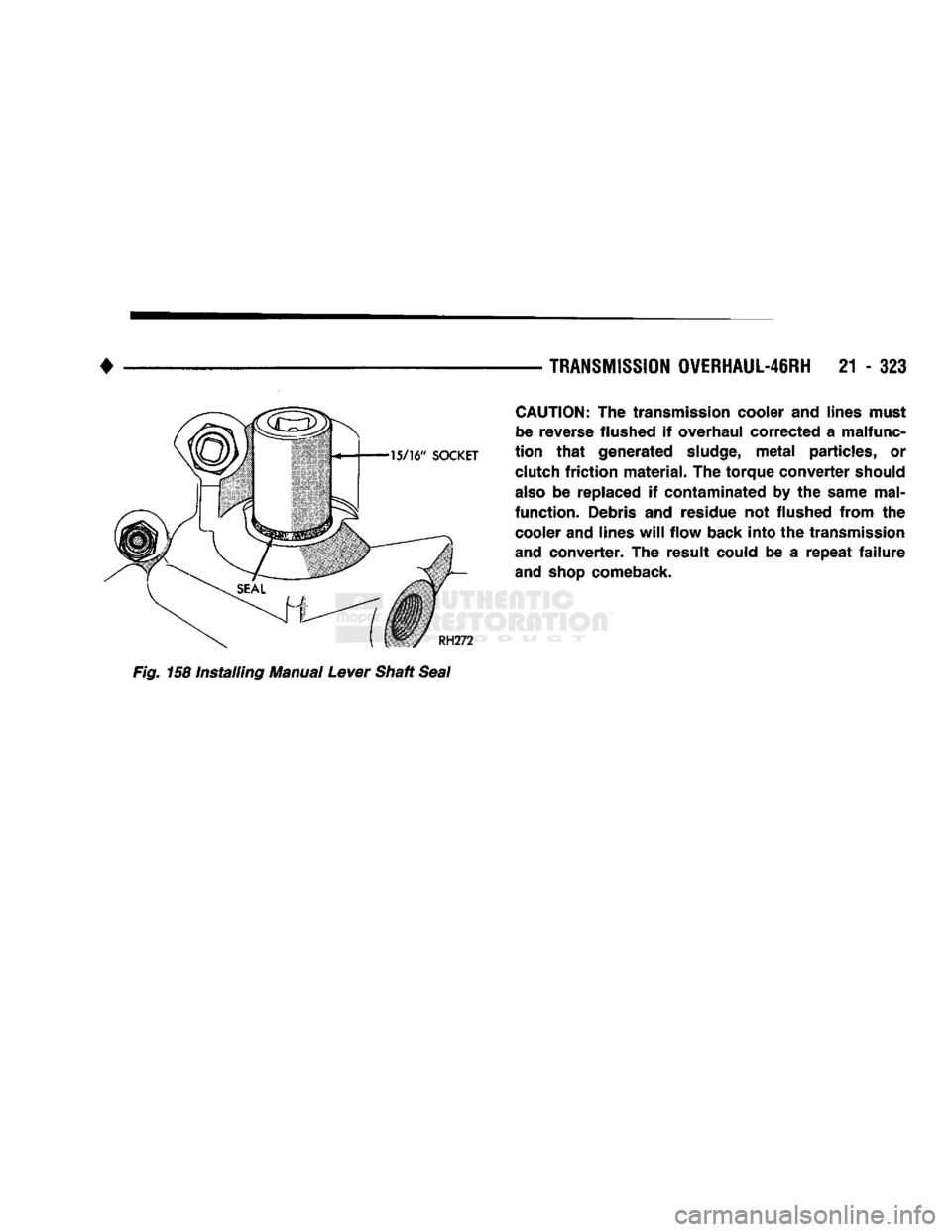
(56) Install new valve body manual shaft seal in
case (Fig. 158). Lubricate seal lip and manual shaft
with petroleum jelly. Start seal over shaft and into
case.
Seat seal with 15/16 inch, deep well socket.
(57) Install throttle valve and shift selector levers
on valve body manual lever shaft. (58) Cap or cover transmission openings (cooler
line fittings, filler tube bore, etc.) to prevent dirt en
try.
(59) Install torque converter. Use C-clamp or metal
strap to hold converter in place for installation. (60) Mount transmission on jack for installation in
vehicle.
(61) Apply dielectric grease to terminal pins of so
lenoid case connector and neutral switch.
Page 1324 of 1502
•
TRANSMISSION
OVERHAUL-46RH
21 - 323
CAUTION:
The transmission cooler and lines must
be reverse flushed if overhaul corrected a malfunc
tion
that
generated
sludge,
metal
particles, or clutch
friction
material. The torque converter should
also
be replaced if contaminated by the same mal
function. Debris and residue not flushed from the cooler and lines
will
flow back into the transmission
and converter. The result could be a
repeat
failure
and
shop
comeback. Fig. 158 Installing Manual Lever Shaft Seal
Page 1340 of 1502
•
OVERDRIVE
UNIT
OVERHAUL—42RH/46RH
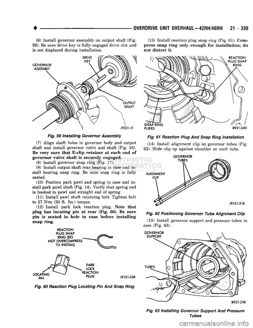
21 - 339 (6) Install governor assembly on output shaft (Fig.
59).
Be sure drive key is fully engaged drive slot and
is not displaced during installation.
Fig.
59 Installing
Governor
Assembly
(7) Align shaft holes in governor body and output
shaft and install governor valve and shaft (Fig. 16).
Be very sure that E-clip retainer at each end of
governor valve shaft is securely engaged.
(8) Install governor snap ring (Fig. 17).
(9) Install output shaft rear bearing in case and in
stall bearing snap ring. Be sure snap ring is fully
seated.
(10) Position park pawl and spring in case and in
stall park pawl shaft (Fig. 14). Verify that spring end
is hooked to pawl and straight end of spring
(11) Install pawl shaft retaining bolt. Tighten bolt
to 27 Nnn (20 ft. lbs.) torque.
(12) Install park lock reaction plug. Note that
plug has locating pin at rear (Fig.
60).
Be sure
pin is seated in hole in case before installing snap ring.
REACTION
Fig.
60 Reaction
Plug
Locating Pin And
Snap
Ring
(13) Install reaction plug snap ring (Fig. 61). Com
press snap ring only enough for installation; do
not distort it.
PLIERS
8921-240
Fig.
61 Reaction
Plug
And
Snap
Ring
Installation
(14) Install alignment clip on governor tubes (Fig.
62).
Slide clip up against shoulder on each tube.
GOVERNOR
Fig.
62
Positioning
Governor
Tube
Alignment
Clip (15) Install governor support and pressure tubes in
case (Fig. 63).
Fig.
63 Installing
Governor
Support
And
Pressure
Tubes
Page 1343 of 1502
21
- 342
NP205 TRANSFER CASE
•
NP205
TRANSFER CASE
INDEX
page
General
Information
342
Recommended Lubricants
342
Service Diagnosis
342
Shift
Linkage
Adjustment
344
Speedometer Service
345
GENERAL
INFORMATION
The NP205 transfer case
is a
heavy duty, part-time
unit with constant mesh, helical gears.
The
gears
are
mounted
in a
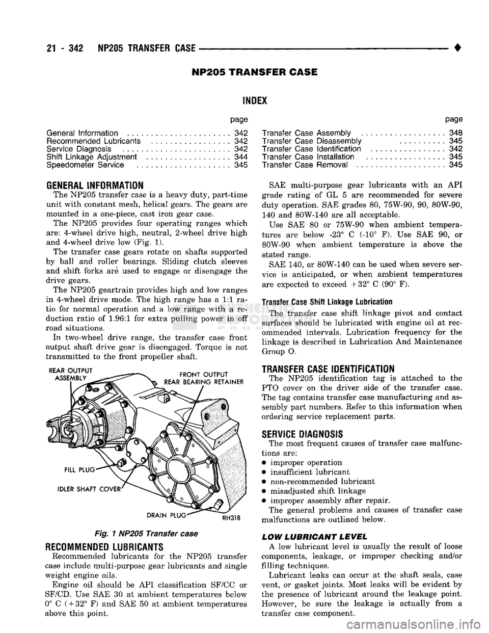
one-piece, cast iron gear case. The NP205 provides four operating ranges which
are:
4-wheel drive high, neutral, 2-wheel drive high
and 4-wheel drive
low (Fig. 1).
The transfer case gears rotate
on
shafts supported
by ball
and
roller bearings. Sliding clutch sleeves and shift forks
are
used
to
engage
or
disengage
the
drive gears. The NP205 geartrain provides high
and low
ranges
in 4-wheel drive mode.
The
high range
has a 1:1 ra
tio
for
normal operation
and a low
range with
a re
duction ratio
of 1.96:1 for
extra pulling power
in off
road situations. In two-wheel drive range,
the
transfer case front
output shaft drive gear
is
disengaged. Torque
is not
transmitted
to the
front propeller shaft.
Fig.
1
NP205 Transfer
case
RECOMMENDED
LUBRICANTS
Recommended lubricants
for the
NP205 transfer
case include multi-purpose gear lubricants
and
single
weight engine oils. Engine
oil
should
be API
classification SF/CC
or
SF/CD.
Use SAE 30 at
ambient temperatures below
0°
C
(
+
32°
F) and SAE 50 at
ambient temperatures
above this point.
page
Transfer
Case
Assembly
348
Transfer
Case
Disassembly
..........
345
Transfer
Case
Identification
342
Transfer
Case
Installation
345
Transfer
Case
Removal
345
SAE multi-purpose gear lubricants with
an API
grade rating
of GL 5 are
recommended
for
severe
duty operation.
SAE
grades
80,
75W-90,
90,
80W-90, 140
and
80W-140
are all
acceptable.
Use
SAE 80 or
75W-90 when ambient tempera
tures
are
below
-23° C (-10° F). Use SAE 90, or
80W-90 when ambient temperature
is
above
the
stated range.
SAE
140, or
80W-140
can be
used when severe ser
vice
is
anticipated,
or
when ambient temperatures are expected
to
exceed +32°
C (90° F).
Transfer Case Shift Linkage Lubrication
The transfer case shift linkage pivot
and
contact
surfaces should
be
lubricated with engine
oil at
rec
ommended intervals. Lubrication frequency
for the
linkage
is
described
in
Lubrication
And
Maintenance Group
O.
TRANSFER CASE
IDENTIFICATION
The NP205 identification
tag is
attached
to the
PTO cover
on the
driver side
of the
transfer case.
The
tag
contains transfer case manufacturing
and as
sembly part numbers. Refer
to
this information when
ordering service replacement parts.
SERVICE
DIAGNOSIS
The most frequent causes
of
transfer case malfunc
tions
are:
• improper operation
• insufficient lubricant
• non-recommended lubricant
• misadjusted shift linkage
• improper assembly after repair. The general problems
and
causes
of
transfer case
malfunctions
are
outlined below.
LOW LUBRICANT LEVEL
A
low
lubricant level
is
usually
the
result
of
loose
components, leakage,
or
improper checking and/or
filling techniques. Lubricant leaks
can
occur
at the
shaft seals, case
vent,
or
gasket joints. Most leaks will
be
evident
by
the presence
of
lubricant around
the
leakage point. However,
be
sure
the
leakage
is
actually from
a
transfer case component.
Page 1344 of 1502
•
NP205 TRANSFER
CASE
21 - 343 Leakage from other sources (engine, transmission,
etc.) can be blown back onto the transfer case by air
flow under the vehicle. A blocked transfer case vent
can also cause leakage at the shaft seals due to in
ternal pressure build up.
Overfilling the transfer case can force fluid out the
vent and be mistaken for a leak. Correct fluid level checking methods should prevent overfill problems.
Checking
Fluid Level The correct method of checking transfer case fluid
level requires that the vehicle be level.
If fluid level is checked with the vehicle parked on
the shop floor, be sure the floor area used is level. If a hoist is used, a drive-on, or swivel arm type is pre
ferred.
Allow the transfer case fluid to settle for a minute
or so before checking. Correct fluid level is to the
bottom edge of the fill plug hole.
HARD SHIFTING
Hard shifting is generally caused by:
• misadjusted or binding linkage
• loose linkage or driveline components
• torque loads caused by 4WD operation on hard
paved surfaces • improper shifting techniques
• lack of lubricant which caused internal wear and
damage.
Loose linkage or driveline components are a result
of improperly tightened, stripped, or missing fasten
ers.
Remember that loose crossmember and mounting
parts can also generate a hard shift condition.
Torque loads in the transfer case can cause hard
shifting or even prevent shifting. Such loads are gen
erally a product of extensive operation on hard,
paved surfaces in 4WD range, unequal size tires, or
by mismatched front/rear axle gear ratios.
Linkage adjustment should be performed as de
scribed in the service section. Improper shift and op
erating techniques can be corrected by instructing
the driver. Internal component damage will require
overhaul to correct.
Failure to lubricate the shift linkage at recom
mended intervals will cause the linkage to bind. If
bind is severe enough to cause hard shifting, the linkage will have to be removed in order to correct
the condition. The linkage can be soaked in auto
matic transmission fluid if necessary. The fluid will
break up accumulated rust and corrosion.
NOISE
Some transfer case operating noise is normal. The
rotating gear train can produce sounds that may be
come audible at higher speeds and loads. However,
unusual noise is an indicator that internal compo nents may be worn or damaged. Low lubricant levels are a frequent cause of noisy
operation. Insufficient lubricant will lead to over
heating, subsequent damage to bearing and gear sur
faces and hard shifting.
Transfer case bearing noise is higher in pitch than
gear noise. If the unit is noisy in 4WD range only,
the front shaft bearings are probably at fault. If the unit is noisy in all ranges, an overhaul will be nec
essary to locate the faulty bearing.
Gear noise is lower in pitch and usually most no
ticeable when engaged and under load. Gear noise in
4WD drive range only is an indicator that the front shaft gears are damaged. Noise in all ranges could be
the idler or drive gears. An overhaul will be neces sary to determine which is at fault.
Frequently, suspected transfer case noise may actu
ally originate from another driveline component. The
proximity of other driveline components can some
times make it difficult to pinpoint the noise source.
TRANSFER CASE OPERATIONAL CHECK
The transfer case should not be removed until di
agnosis indicates the unit has actually malfunc
tioned. If a transfer case problem is suspected, check and verify operation before attempting repair. A
transfer case operational check may reveal that a
problem is actually related to another driveline com ponent.
(1) Raise vehicle on a hoist that will allow all four
wheels to rotate. (2) Check lubricant level. If lubricant level is low,
check for leaks at the bearing and seal retainers,
yokes,
drain/fill plugs, PTO cover and vent. (3) If vehicle is equipped with locking hubs, en
gage hubs. (4) Start engine, shift transmission into gear and
operate transfer case in all ranges. Observe propeller shaft action, shift efforts and operational sound lev
els as follows: (a) Only the rear propeller shaft should rotate in
two-wheel drive. Both propeller shafts should both
rotate in four-wheel drive high and low ranges. (b) If the front propeller shaft did not rotate in
either four-wheel drive range, the transfer case shift components may be worn or damaged. Or, if
the front shaft did rotate but the front wheels did
not, check the front axle shift mechanism and the locking hubs (if equipped). (c) If both propeller shafts rotate in four-wheel
drive but the wheels on one axle did not rotate, the
problem is in the axle. (d) If neither propeller shaft rotates in any
range, the problem is in the transmission or trans fer case. To determine which component is at fault,
proceed to next step. (5) Determine if fault is with transfer case or
transmission as follows: