1993 DODGE TRUCK torque
[x] Cancel search: torquePage 1221 of 1502
21
- 220
TRANSMISSION OVERHAUL—36RH/37RH
•
VALVE
BODY CLEANING AND INSPECTION
The only serviceable valve body components are
the:
• park lock rod and E-clip
• switch valve and spring
• pressure adjusting screw bracket
• throttle valve lever
• manual shaft
• manual shaft seal/washer/E-clip/detent ball
• fluid filter.
The remaining valve body components are serviced
only as part of a complete valve body assembly (Fig.
92).
Clean the valve body components in a parts clean
ing solution only. Do not use gasoline, kerosene, or
any type of caustic solution.
Dry the parts with compressed air. Make sure all
passages are clean and free from obstructions. Do not use rags or shop towels to dry or wipe
off valve body components unless they are made
from lint free material. Lint will adhere to the
valve body components causing valve bind. Lint
can also clog filters and small fluid passages.
Inspect the throttle and manual valve levers and
shafts.
Do not attempt to straighten a bent shaft
or correct a loose lever. Replace these compo
nents if worn, bent, loose or damaged in any way.
Inspect all of the valve body mating surfaces for
scratches, nicks, burrs, or distortion. Use a straight
edge to check surface flatness. Minor scratches may
be removed with crocus cloth using only very light pressure.
Minor distortion of a valve body mating surface
may be corrected by smoothing the surface with cro
cus cloth. Position the crocus cloth sheet on a surface
plate, sheet of plate glass, or equally flat surface. If distortion is severe or any surfaces are heavily
scored, the valve body will have to be replaced.
CAUTION:
The
throttle
valve, shuttle valve plug,
1-2
shift valve
and 1-2
governor plug
are
made
of
coated aluminum. Aluminum components
can be
identified
by the
dark color
of the
special coating
applied
to the
surface
(or by
testing
with
a
magnet).
DO
NOT
polish
or
sand
aluminum valves
or
plugs
with
any
type
of
material,
or
under
any
circum
stances.
This practice
will
remove
the
special coat
ing
and
cause
the
valves
and
plugs
to
stick
and
bind.
Inspect the valves and plugs for scratches, burrs,
nicks,
or scores. Also inspect the coating on the alu
minum valves and plugs. If the coating is damaged
or worn through, the valve (or valve body) should be
replaced.
Aluminum valves and plugs must not be sanded or
polished under any circumstances. However, minor burrs or scratches on steel valves and plugs can be
removed with crocus cloth but do not round off the
valve or plug edges. Squareness of these edges is vi
tally important; they prevent foreign matter from lodging between the valves and plugs and the bore.
Inspect all the valve and plug bores in the valve
body. Use a penlight to view the bore interiors. Re
place the valve body if any bores are distorted or scored. Inspect all of the valve body springs. The
springs must be free of distortion, warpage or broken
coils.
Trial fit each valve and plug in its bore to check
freedom of operation. When clean and dry, the valves and plugs should drop freely into the bores.
Valve body bores do not change dimensionally with
use.
If the valve body functioned correctly when new,
it will continue to operate properly after cleaning and inspection. It should not be necessary to replace a valve body assembly unless it is damaged in han
dling.
VALVE BODY ASSEMBLY
CAUTION:
Do not
force
the
valves
or
plugs
into place during reassembly.
If the
valve body bores
and
the
valves
and
plugs
are
free
of
distortion
or
burrs,
the
valves
and
plugs
should slide into place
easily.
In
addition,
do not
overtighten
the
transfer plate
and
valve body screws during reassembly.
Overtightening
can
distort
the
valve body resulting
in valve sticking,
cross
leakage
and
unsatisfactory
operation. Tighten
the
screws
alternately
and
evenly
to 4 Nnn (35 in.
lbs.) torque only.
(1) Lubricate valve body bores, valves and plugs
with ATF Plus, or Dexron II™ transmission fluid.
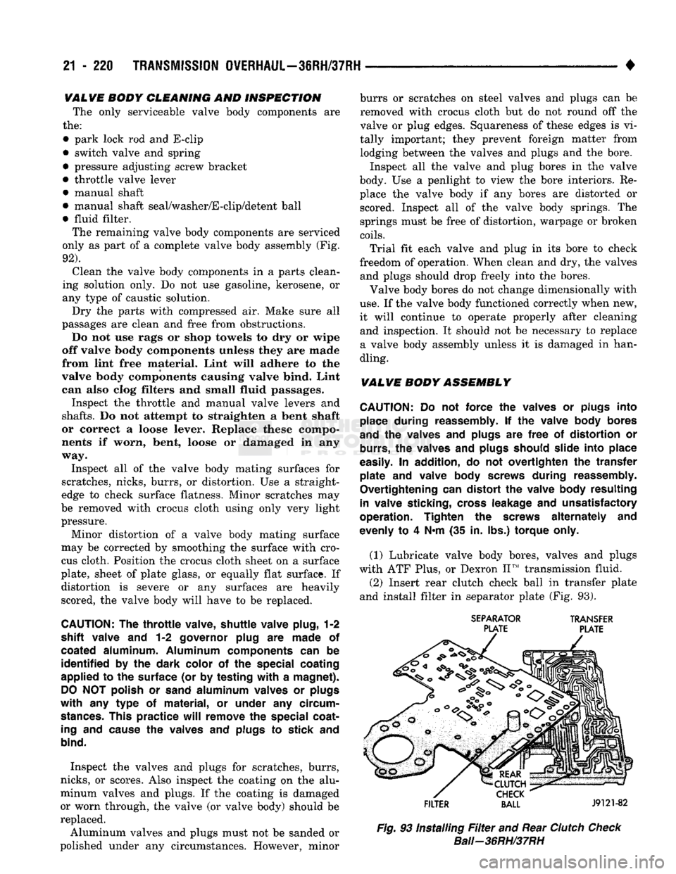
(2) Insert rear clutch check ball in transfer plate
and install filter in separator plate (Fig. 93).
SEPARATOR
TRANSFER
PLATE PLATE
FILTER
BALL
J9121-82
Fig.
93 Installing
Filter
and Rear
Clutch
Check
Bali—36RH/37RH
Page 1222 of 1502
•
TRANSMISSION
OVERHAUL—36RH/37RH
21 - 221 (3) Align and install separator plate on transfer
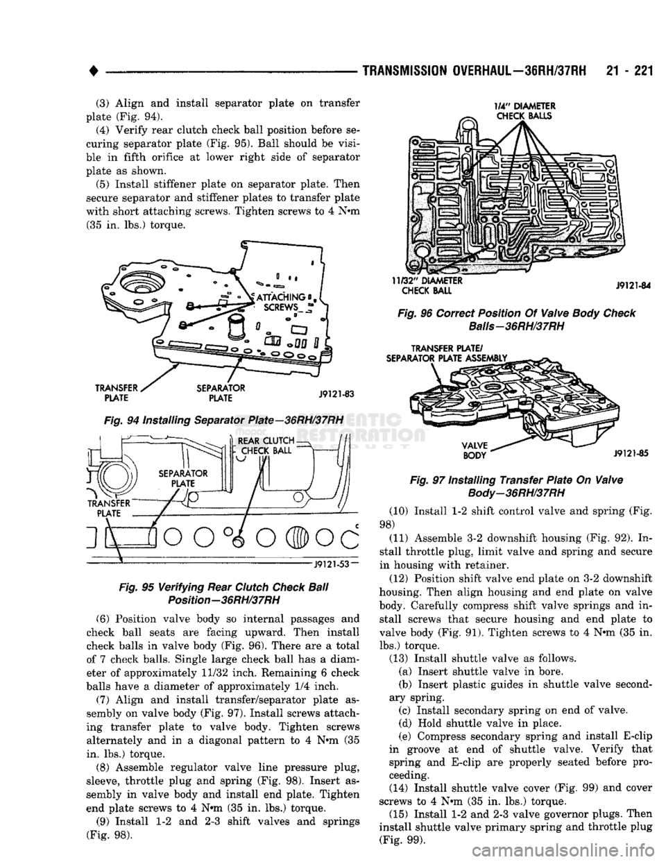
plate (Fig. 94). (4) Verify rear clutch check ball position before se
curing separator plate (Fig. 95). Ball should be visi
ble in fifth orifice at lower right side of separator plate as shown.
(5) Install stiffener plate on separator plate. Then
secure separator and stiffener plates to transfer plate
with short attaching screws. Tighten screws to 4 Nnn (35 in. lbs.) torque. 1/4"
DIAMETER
CHECK
BALLS
TRANSFER
PLATE
SEPARATOR
PLATE
J9121-83
Fig.
94 Installing Separator Plate—36RH/37RH f^-^. )
REAR CLUTCH-
J9121-53-
Fig.
95
Verifying
Rear
Clutch
Check
Ball
Position-36RH/37RH (6) Position valve body so internal passages and
check ball seats are facing upward. Then install
check balls in valve body (Fig. 96). There are a total
of 7 check balls. Single large check ball has a diam eter of approximately 11/32 inch. Remaining 6 check
balls have a diameter of approximately 1/4 inch.
(7) Align and install transfer/separator plate as
sembly on valve body (Fig. 97). Install screws attach
ing transfer plate to valve body. Tighten screws alternately and in a diagonal pattern to 4 Nnn (35
in. lbs.) torque.
(8) Assemble regulator valve line pressure plug,
sleeve, throttle plug and spring (Fig. 98). Insert as
sembly in valve body and install end plate. Tighten
end plate screws to 4 Nnn (35 in. lbs.) torque.
(9) Install 1-2 and 2-3 shift valves and springs
(Fig. 98).
11/32"
DIAMETER
CHECK
BALL
J9121-84
Fig.
96 Correct Position Of
Valve
Body Check
Balis-36RH/37RH
TRANSFER
PLATE/
SEPARATOR
PLATE ASSEMBLY
VALVE
BODY
J9121-85
Fig.
97 Installing Transfer
Plate
On
Valve
Body-36RH/37RH
(10) Install 1-2 shift control valve and spring (Fig.
98) (11) Assemble 3-2 downshift housing (Fig. 92). In
stall throttle plug, limit valve and spring and secure
in housing with retainer.
(12) Position shift valve end plate on 3-2 downshift
housing. Then align housing and end plate on valve
body. Carefully compress shift valve springs and in stall screws that secure housing and end plate to
valve body (Fig. 91). Tighten screws to 4 Nnn (35 in.
lbs.) torque.
(13) Install shuttle valve as follows. (a) Insert shuttle valve in bore.
(b) Insert plastic guides in shuttle valve second
ary spring. (c) Install secondary spring on end of valve.
(d) Hold shuttle valve in place.
(e) Compress secondary spring and install E-clip
in groove at end of shuttle valve. Verify that
spring and E-clip are properly seated before pro
ceeding. (14) Install shuttle valve cover (Fig. 99) and cover
screws to 4 Nnn (35 in. lbs.) torque. (15) Install 1-2 and 2-3 valve governor plugs. Then
install shuttle valve primary spring and throttle plug (Fig. 99).
Page 1224 of 1502
•
TRANSMISSION
OVERHAUL—36RH/37RH
21 - 223 (16) Align and install governor plug end plate
(Fig. 99) on valve body and install end plate screws.
Tighten screws to 4 N»m (35 in. lbs.) torque.
(17) Install manual valve (Fig. 99). (18) Install throttle valve and spring. Then install
kickdown valve and detent (Fig. 99). (19) Install pressure regulator valve and switch
valve (Fig. 99).
(20) Install manual lever detent spring in housing.
Place detent ball on end of spring and push ball and spring into housing. Secure ball and spring with Re
tainer Tool 6583 (Fig. 88).
(21) Insert line pressure adjusting screw in adjust
ing screw bracket (Fig. 92).
(22) Place valve spring on end of line pressure reg
ulator valve.
(23) Install switch valve spring on tang at end of
adjusting screw bracket (Fig. 87). (24) Install adjusting screw bracket on valve body.
Align springs, press bracket toward valve body and install long bottom bracket attaching screw first. Do
not tighten screw fully at this time.
(25) Carefully align bracket on valve body and
transfer plate and install remaining (two) bracket screws. Verify that valve springs and bracket are
properly aligned. Then tighten all three bracket screws to 4 N*m (35 in. lbs.) torque.
(26) Install throttle lever in valve body. Then in
stall manual lever over throttle lever and start man
ual lever into valve body.
(27) Align manual lever detent with detent ball
and align lever arm with manual valve. Hold throt
tle lever upward. Then press down on manual lever until lever is fully seated.
(28) Install manual lever seal, washer and retain
ing E-clip.
(29) Lubricate shaft of manual lever with light
coat of petroleum jelly. This will help protect seal lip
when manual shaft seal is installed.
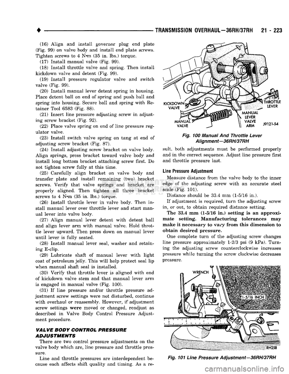
(30) Verify that throttle lever is aligned with end
of kickdown valve stem and that manual lever arm
is engaged in manual valve (Fig. 100).
(31) If line pressure and/or throttle pressure ad
justment screw settings were not disturbed, continue with overhaul or reassembly. However, if adjustment screw settings were moved or changed, readjust as
described in Valve Body Control Pressure Adjust
ment procedure.
VALVE BODY CONTROL
PRESSURE
ADJUSTMENTS
There are two control pressure adjustments on the
valve body which are, line pressure and throttle pres
sure.
Line and throttle pressures are interdependent be
cause each affects shift quality and timing. As a re-
Fig.
100 Manual And
Throttle
Lever
Alignment-36RH/37RH
suit, both adjustments must be performed properly
and in the correct sequence. Adjust line pressure first
and throttle pressure last.
Line
Pressure
Adjustment Measure distance from the valve body to the inner
edge of the adjusting screw with an accurate steel scale (Fig. 101).
Distance should be 33.4 mm (1-5/16 in.).
If adjustment is required, turn the adjusting screw
in, or out, to obtain required distance setting. The 33.4 mm (1-5/16 in.) setting is an approxi
mate setting. Manufacturing tolerances may
make it necessary to vary from this dimension to obtain desired pressure.
One complete turn of the adjusting screw changes
line pressure approximately 1-2/3 psi (9 kPa). Turn
ing the adjusting screw counterclockwise increases
pressure while turning the screw clockwise decreases
pressure.
Fig.
101
Line
Pressure
Adjustment—36RH/37RH
Page 1227 of 1502
21
- 226
TRANSMISSION
OVERHAUL—36RH/37RH
•
REACTION PIN
O-RINGS
J9121-91
Fig.
109 Installing Rear
Band
Reaction
Pin—36RH/
37RH
ADJUSTING
SCREW
ADJUSTING
LEVER
REACTION LEVER
•STRUT
J9121-92
Fig.
110 Rear
Band
Levers
And Strut—36RH/37RH (11) Lubricate front servo piston components and
servo bore in case with transmission fluid.
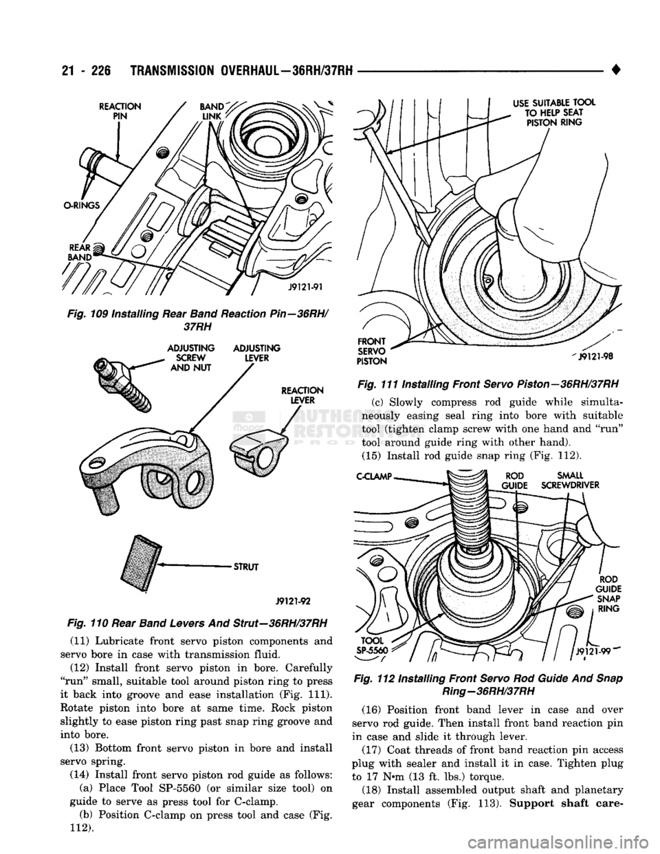
(12) Install front servo piston in bore. Carefully
"run" small, suitable tool around piston ring to press
it back into groove and ease installation (Fig. 111).
Rotate piston into bore at same time. Rock piston
slightly to ease piston ring past snap ring groove and
into bore.
(13) Bottom front servo piston in bore and install
servo spring.
(14) Install front servo piston rod guide as follows: (a) Place Tool SP-5560 (or similar size tool) on
guide to serve as press tool for C-clamp. (b) Position C-clamp on press tool and case (Fig.
112).
USE
SUITABLE
TOOL
TO HELP SEAT PISTON RING
FRONT
SERVO
PISTON
-J9121-98
Fig.
111 Installing Front
Servo
Piston—36RH/37RH
(c) Slowly compress rod guide while simulta
neously easing seal ring into bore with suitable
tool (tighten clamp screw with one hand and "run"
tool around guide ring with other hand). (15) Install rod guide snap ring (Fig. 112).
C-CLAMP
ROD
SMALL
GUIDE SCREWDRIVER
ROD
GUIDE
SNAP
RING
J9121-99"
Fig.
112 Installing Front
Servo
Rod
Guide
And
Snap
Ring—36RH/37RH
(16) Position front band lever in case and over
servo rod guide. Then install front band reaction pin
in case and slide it through lever.
(17) Coat threads of front band reaction pin access
plug with sealer and install it in case. Tighten plug to 17 Nnn (13 ft. lbs.) torque.
(18) Install assembled output shaft and planetary
gear components (Fig. 113). Support shaft care-
Page 1228 of 1502
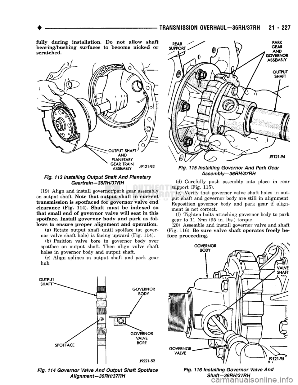
•
fully during Installation. Do not allow shaft
bearing/bushing surfaces to become nicked or
scratched. ASSEMBLY JY,iM^
Fig.
113 installing Output Shaft And Planetary Geartrain-36RH/37RH (19) Align and install governor/park gear assembly
on output shaft. Note that output shaft In current
transmission is spotfaced for governor valve end clearance (Fig. 114). Shaft must be indexed so
that small end of governor valve will seat in this spotface. Install governor body and park as fol
lows to ensure proper alignment and operation.
(a) Rotate output shaft until spotface (at gover
nor valve shaft hole) is facing upward (Fig. 114). (b) Position valve bore in governor body over
spotface on output shaft. Then align valve shaft
holes in governor body and output shaft.
(c) Align splines in output shaft and park gear
hub.
J9221-52
TRANSMISSION
OVERHAUL—36RH/37RH
21 - 227
Fig.
115 Installing
Governor
And
Park
Gear
Assembly-36RH/37RH
(d) Carefully push assembly into place in rear
support (Fig. 115).
(e) Verify that governor valve shaft holes in out
put shaft and governor body are still in alignment. Reposition governor body and park gear if align
ment is not correct.
(f) Tighten bolts attaching governor body to park
gear to 11 N-m (95 in. lbs.) torque. (20) Assemble and install governor valve and shaft
(Fig. 116). Be sure valve shaft operates freely be
fore proceeding.
Fig.
114
Governor
Valve
And Output Shaft Spotface
Alignment-36RH/37RH
Fig.
116 Installing
Governor
Valve
And
Shaft-36RH/37RH
Page 1231 of 1502
21
- 230
TRANSMISSION
OWERHAUL-3IRH/37RH
•
J9121-103
Fig.
124 Installing Oil
Pump
Gasket
And Pilot
Studs-36RH/37RH
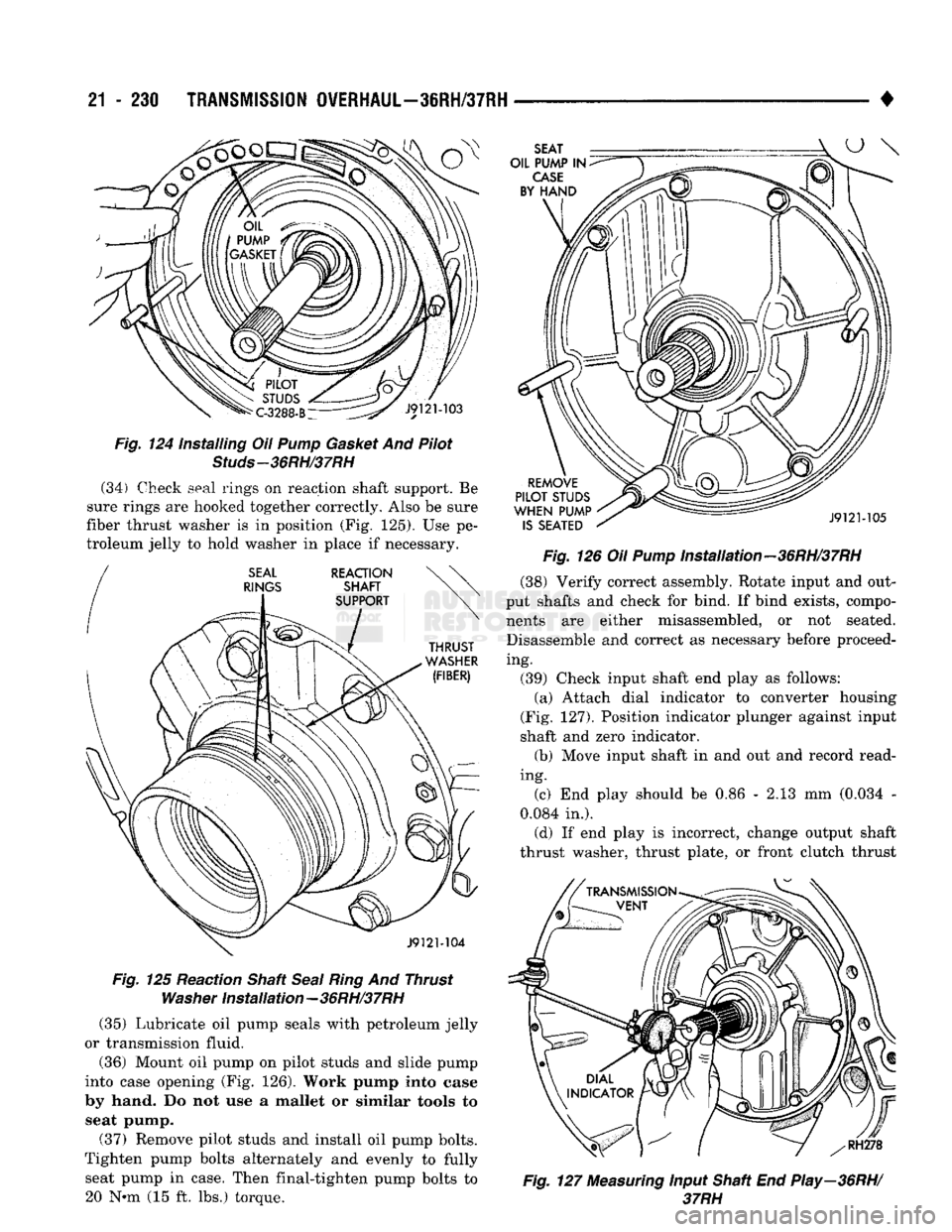
(34) Check seal rings on reaction shaft support. Be
sure rings are hooked together correctly. Also be sure
fiber thrust washer is in position (Fig. 125). Use pe
troleum jelly to hold washer in place if necessary. J9121-104
Fig.
125 Reaction Shaft
Seal
Ring
And Thrust
Washer
Installation-36RH/37RH (35) Lubricate oil pump seals with petroleum jelly
or transmission fluid.
(36) Mount oil pump on pilot studs and slide pump
into case opening (Fig. 126). Work pump into case
by hand. Do not use a mallet or similar tools to seat pump.
(37) Remove pilot studs and install oil pump bolts.
Tighten pump bolts alternately and evenly to fully seat pump in case. Then final-tighten pump bolts to 20 Nnn (15 ft. lbs.) torque. SEAT
OIL PUMP IN
CASE
BY HAND
REMOVE
PILOT STUDS
WHEN PUMP IS SEATED J9121-105
Fig.
126 Oil
Pump
Installation-36RH/37RH (38) Verify correct assembly. Rotate input and out
put shafts and check for bind. If bind exists, compo nents are either misassembled, or not seated. Disassemble and correct as necessary before proceed
ing. (39) Check input shaft end play as follows: (a) Attach dial indicator to converter housing
(Fig. 127). Position indicator plunger against input
shaft and zero indicator. (b) Move input shaft in and out and record read
ing. (c) End play should be 0.86 - 2.13 mm (0.034 -
0.084 in.). (d) If end play is incorrect, change output shaft
thrust washer, thrust plate, or front clutch thrust
f
RH278
Fig.
127
Measuring
Input Shaft End Play—36RH/
37RH
Page 1232 of 1502
#
s ; _
TRANSMISSION
OWERHAUL—38RH/37RH
21 - 231
washer as needed. Thrust washer is select and
comes in three thicknesses.
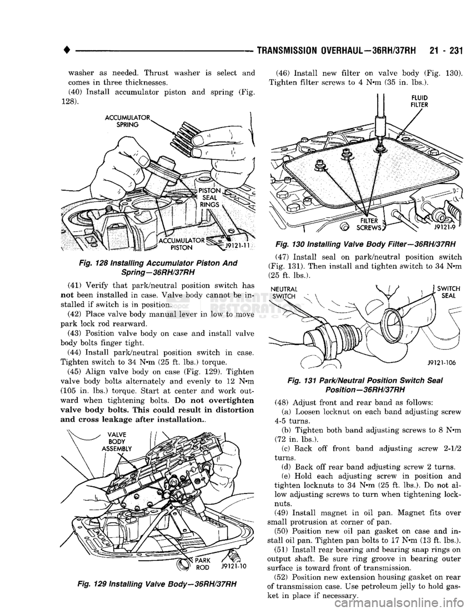
(40) Install accumulator piston and spring (Fig.
128). Fig.
128 Installing
Accumulator
Piston
And
Spring-36RH/37RH
(41) Verify that park/neutral position switch has
not been installed in case. Valve body cannot be in stalled if switch is in position.
(42) Place valve body manual lever in low to move
park lock rod rearward.
(43) Position valve body on case and install valve
body bolts finger tight.
(44) Install park/neutral position switch in case.
Tighten switch to 34 Nnn (25 ft. lbs.) torque.
(45) Align valve body on case (Fig. 129). Tighten
valve body bolts alternately and evenly to 12 Nnn (105 in. lbs.) torque. Start at center and work out
ward when tightening bolts. Do not overtighten
valve body bolts. This could result in distortion and cross leakage after installation..
Fig.
129 Installing
Valve
Body-36RH/37RH
(46) Install new filter on valve body (Fig. 130).
Tighten filter screws to 4 Nnn (35 in. lbs.).
Fig.
130 Installing
Valve
Body
Filter-36RH/37RH
(47) Install seal on park/neutral position switch
(Fig. 131). Then install and tighten switch to 34 Nnn
(25 ft. lbs.).
Fig.
131 Park/Neutral Position
Switch
Seal
Position-36RH/37RH
(48) Adjust front and rear band as follows:
(a) Loosen locknut on each band adjusting screw
4-5 turns. (b) Tighten both band adjusting screws to 8 Nnn
(72 in. lbs.).
(c) Back off front band adjusting screw 2-1/2
turns.
(d) Back off rear band adjusting screw 2 turns.
(e) Hold each adjusting screw in position and
tighten locknuts to 34 Nnn (25 ft. lbs.). Do not al low adjusting screws to turn when tightening lock-
nuts.
(49) Install magnet in oil pan. Magnet fits over
small protrusion at corner of pan. (50) Position new oil pan gasket on case and in
stall oil pan. Tighten pan bolts to 17 Nnn (13 ft. lbs.).
(51) Install rear bearing and bearing snap rings on
output shaft. Be sure ring groove in bearing outer surface is toward front of transmission. (52) Position new extension housing gasket on rear
of transmission case. Use petroleum jelly to hold gas
ket in place if necessary.
Page 1233 of 1502
21 - 232
TRANSMISSION OVERHAUL—36RH/37RH
• (53) Spread rear bearing locating ring and start
extension housing on output shaft and rear bearing. (54) Align park rod in sprag and work housing
into place. Install and tighten housing bolts to 43
Nin (32 ft. lbs,).
(55) Install rear bearing locating ring access cover
and gasket. (56) Remove repair stand and turn transmission
over.
(57) Install new valve body manual shaft seal in
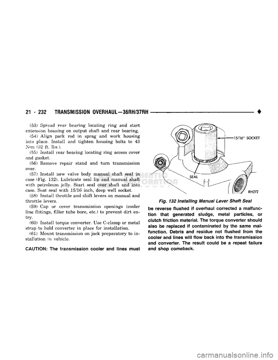
case (Fig. 132). Lubricate seal lip and manual shaft
with petroleum jelly. Start seal over shaft and into
case.
Seat seal with 15/16 inch, deep well socket.
(58) Install throttle and shift levers on manual and
throttle levers. (59) Cap or cover transmission openings (cooler
line fittings, filler tube bore, etc.) to prevent dirt en
try.
(60) Install torque converter. Use C-clamp or metal
strap to hold converter in place for installation. (61) Mount transmission on jack preparatory to in
stallation in vehicle.
CAUTION;
The
transmission cooler
and
lines must Fig.
132 Installing Manual
Lever
Shaft
Seal
be reverse flushed
if
overhaul corrected
a
malfunc
tion
that
generated
sludge,
metal
particles,
or
clutch friction material.
The
torque converter should
also
be
replaced
if
contaminated
by the
same mal
function. Debris
and
residue
not
flushed from
the
cooler and lines
will
flow back into
the
transmission
and
converter.
The
result could
be a
repeat
failure
and
shop
comeback.