1993 DODGE TRUCK engine
[x] Cancel search: enginePage 35 of 1502
0-18
LUBRICATION
AND
MAINTENANCE
•
COOLANT FREEZE PROTECTION
Cooling systems contain a 50/50 mixture of anti
freeze (ethylene glycol) and distilled water. This is
the recommended coolant mixture.
It is recommended that the degree of coolant pro
tection be tested every 12 months. If the coolant is
contaminated or rusty, the cooling system should be
drained, flushed. Refill with a 50/50 mixture of fresh
coolant. Refer to Group 7—Cooling Systems for addi
tional information.
SYSTEM
INSPECTION
WARNING:
IF THE
ENGINE
HAS
BEEN RECENTLY
OPERATED,
DO NOT
REMOVE
THE
RADIATOR
CAP.
THIS WILL AVOID
YOU
BEING SCALDED
WITH
HOT, PRESSURIZED COOLANT.
(1) Test the radiator cap for proper sealing and op
eration. Use caution when removing the radiator cap
to avoid contact with hot coolant. Place a heavy rag
or towel over the cap and turn to the first stop. Do
not press down. Pause to allow the pressure to re
lease through the overflow tube. Then press down
and turn counterclockwise to remove the cap.
(2) Inspect the coolant overflow tubing and the
connections at the coolant reserve tank and at the
radiator.
(3) Inspect the entire cooling system for leaks. A
black-light detector can be used as an aid in detect ing the source of coolant leaks.
(4) Inspect the radiator and air conditioner con
denser fins for debris, etc. (5) If necessary, refer to Group 7—Cooling Systems
for additional information and service procedures.
RADIATOR CAP
The radiator cap must be completely tightened to
provide proper pressure. Inspect and test radiator cap
when cooling system service is performed.
MAIN,
FLUSH
AND
FILL
WARNING: ANTI-FREEZE (ETHYLENE GLYCOL)
IS
POISONOUS.
KEEP
OUT OF THE
REACH
OF
CHIL
DREN.
Drain, flush, and fill the cooling system at the in
terval specified in maintenance schedule. For proper service instructions see Group 7, Cooling System.
HOSES AND
FITTINGS
It is recommended that rubber hoses be periodi
cally inspected. Inspect all hose fittings for looseness and corrosion.
ENGINE
AIR
CLEANER
FILTER
ELEMENT
MAINTENANCE
SCHEDULE
With normal driving conditions, the engine air
cleaner filter element should be replaced:
• Light-Duty Cycle-after each 48 000 km (30,000
miles) interval has elapsed
• Heavy-Duty Cycle-after
each
38 000 km (24,000
miles) interval has elapsed
When the vehicle is operated in dusty areas, the
filter element should be replaced more often.
For Diesel engines, the air filter canister should be
cleaned at the same time the filter is replaced.
SERVICE/REPLACEMENT
(1) Remove the air cleaner cover.
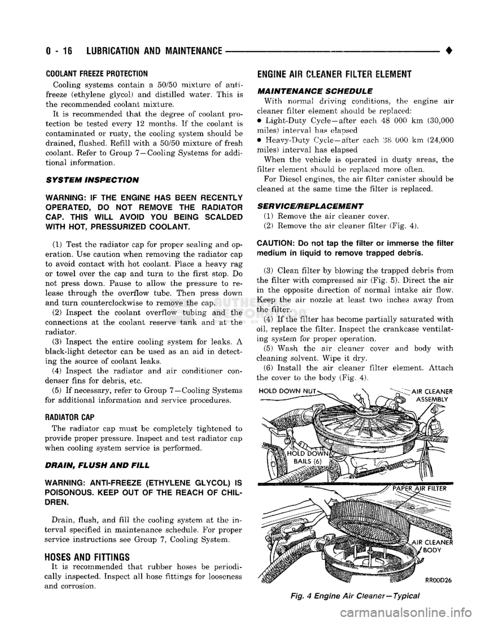
(2) Remove the air cleaner filter (Fig. 4).
CAUTION:
Do not tap the filter or immerse the filter medium in liquid to remove trapped debris.
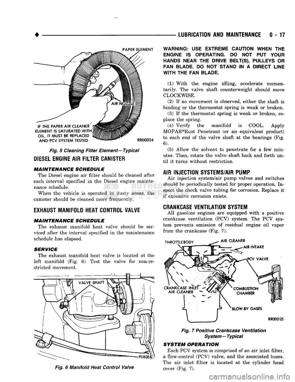
(3) Clean filter by blowing the trapped debris from
the filter with compressed air (Fig. 5). Direct the air in the opposite direction of normal intake air flow.
Keep the air nozzle at least two inches away from
the filter.
(4) If the filter has become partially saturated with
oil,
replace the filter. Inspect the crankcase ventilat
ing system for proper operation.
(5) Wash the air cleaner cover and body with
cleaning solvent. Wipe it dry.
(6) Install the air cleaner filter element. Attach
the cover to the body (Fig. 4).
Fig,
4
Engine
Air Oeaner—
Typical
Page 36 of 1502
•
Fig.
5
Cleaning
Filter
Element—Typical
DIESEL
ENGINE
AIR
FILTER CANISTER MAINTENANCE SCHEDULE
The Diesel engine air filter should be cleaned after
each interval specified in the Diesel engine mainte
nance schedule.
When the vehicle is operated in dusty areas, the
canister should be cleaned more frequently.
EXHAUST
MANIFOLD HEAT CONTROL VALVE
MAINTENANCE SCHEDULE
The exhaust manifold heat valve should be ser
viced after the interval specified in the maintenance schedule has elapsed.
SERVICE The exhaust manifold heat valve is located at the
left manifold (Fig. 6). Test the valve for non-re stricted movement.
Fig.
6 Manifold Heat Control
Valve
LUBRICATION
AND
MAINTENANCE
0 - 17
Fig.
7 Positive
Crankcase
Ventilation
System—Typical
SYSTEM OPERATION
Each PCV system is comprised of an air inlet filter,
a flow-control (PCV) valve, and the associated hoses.
The air inlet filter is located at the cylinder head cover (Fig. 7).
WARNING:
USE
EXTREME CAUTION WHEN
THE
ENGINE
IS
OPERATING.
DO NOT PUT
YOUR
HANDS NEAR
THE
DRIVE BELT(S), PULLEYS
OR
FAN BLADE.
DO NOT
STAND
IN A
DIRECT LINE
WITH
THE FAN
BLADE.
(1) With the engine idling, accelerate momen
tarily. The valve shaft counterweight should move CLOCKWISE.
(2) If no movement is observed, either the shaft is
binding or the thermostat spring is weak or broken. (3) If the thermostat spring is weak or broken, re
place the spring.
(4) Verify the manifold is COOL. Apply
MOPAR®Rust Penetrant (or an equivalent product)
to each end of the valve shaft at the bearings (Fig.
6).
(5) Allow the solvent to penetrate for a few min
utes.
Then, rotate the valve shaft back and forth un
til it turns without restriction.
AIR INJECTION SYSTEMS/AIR PUMP
Air injection system/air pump valves and switches
should be periodically tested for proper operation. In
spect the check valve tubing for corrosion. Replace it
if excessive corrosion exists.
CRANKCASE
VENTILATION
SYSTEM
All gasoline engines are equipped with a positive
crankcase ventilation (PCV) system. The PCV sys
tem prevents emission of residual engine oil vapor
from the crankcase (Fig. 7).
Page 37 of 1502
0-18
LUBRICATION
AND
MAINTENANCE
• MAINTENANCE SCHEDULE
A crankcase ventilation system must be clean to
provide good operation and durability. Periodic main
tenance is necessary. Replace the PCV valve. Re
move residual combustion deposits from the hoses and throttle body/intake manifold passages.
The PCV valve should be replaced and the system
should be serviced at the interval specified in main
tenance schedule. If a vehicle is routinely used for short trips, the crankcase ventilation system could
possibly require more maintenance.
CRANKCASE AIR INLET FILTER
MAINTENANCE SCHEDULE Replace or clean, the air inlet filter at the interval
specified in maintenance schedule.
More frequent PCV system maintenance could be
required for:
• Vehicles routinely used for short trips
• Vehicles routinely involved in stop and go traffic
operation
• Vehicles routinely involved in extended periods of
engine idle
MAINTENANCE Clean and lubricate the crankcase air inlet filter
according to the following procedure. (1) Disconnect the fresh air hose from the port on
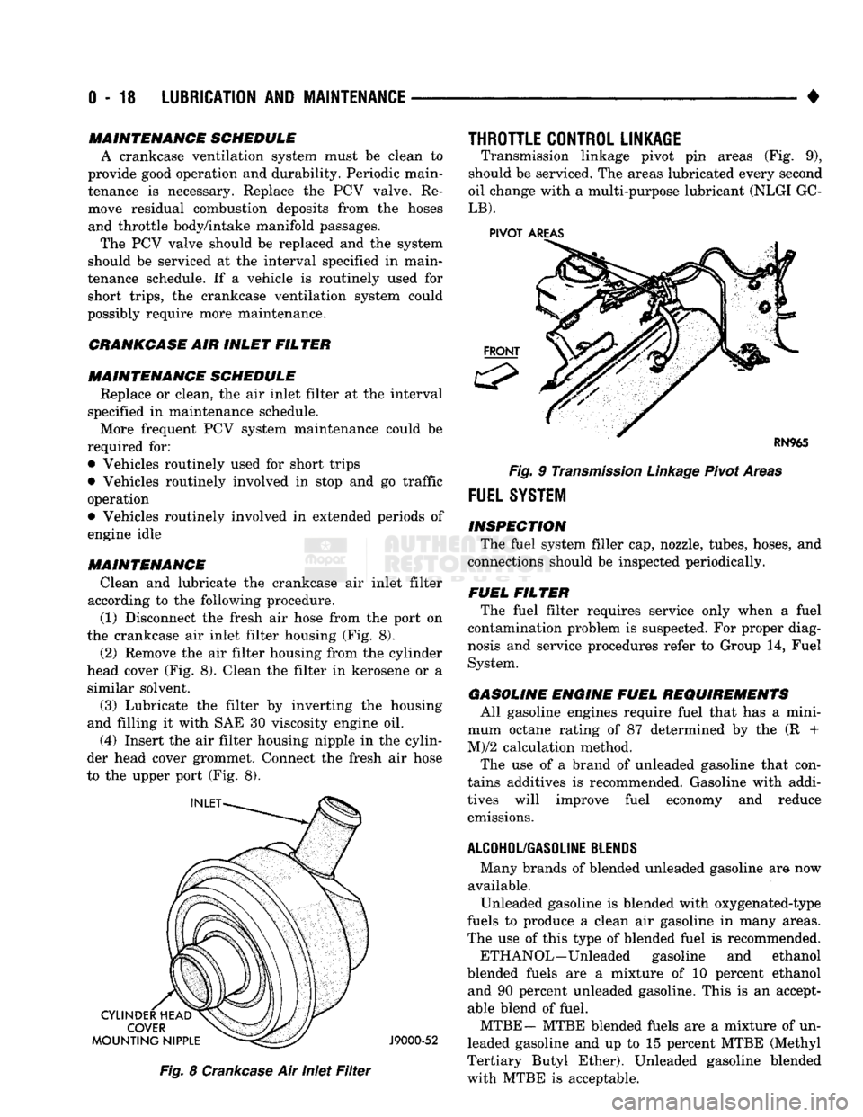
the crankcase air inlet filter housing (Fig. 8).
(2) Remove the air filter housing from the cylinder
head cover (Fig. 8). Clean the filter in kerosene or a similar solvent.
(3) Lubricate the filter by inverting the housing
and filling it with SAE 30 viscosity engine oil.
(4) Insert the air filter housing nipple in the cylin
der head cover grommet. Connect the fresh air hose
to the upper port (Fig. 8).
J9000-52
Fig.
8
Crankcase
Air Inlet
Filter
THROTTLE CONTROL LINKAGE
Transmission linkage pivot pin areas (Fig. 9),
should be serviced. The areas lubricated every second
oil change with a multi-purpose lubricant (NLGI GC-
LB).
PIVOT
AREAS
Fig.
9
Transmission
Linkage
Pivot Areas
FUEL
SYSTEM
INSPECTION The fuel system filler cap, nozzle, tubes, hoses, and
connections should be inspected periodically.
FUEL FILTER The fuel filter requires service only when a fuel
contamination problem is suspected. For proper diag
nosis and service procedures refer to Group 14, Fuel
System.
GASOLINE ENGINE FUEL REQUIREMENTS All gasoline engines require fuel that has a mini
mum octane rating of 87 determined by the (R +
M)/2 calculation method.
The use of a brand of unleaded gasoline that con
tains additives is recommended. Gasoline with addi
tives will improve fuel economy and reduce emissions.
ALCOHOL/GASOLINE
BLENDS
Many brands of blended unleaded gasoline am now
available. Unleaded gasoline is blended with oxygenated-type
fuels to produce a clean air gasoline in many areas.
The use of this type of blended fuel is recommended.
ETH ANOL—Unleaded gasoline and ethanol
blended fuels are a mixture of 10 percent ethanol and 90 percent unleaded gasoline. This is an accept
able blend of fuel.
MTBE— MTBE blended fuels are a mixture of un
leaded gasoline and up to 15 percent MTBE (Methyl
Tertiary Butyl Ether). Unleaded gasoline blended
with MTBE is acceptable.
Page 38 of 1502

•
LUBRICATION
AND
MAINTENANCE
0 - 19 ETBE— This fuel is a mixture of unleaded gasoline
and up to 17 percent ETBE (Ethyl Tertiary Butyl
Ether).
Unleaded gasoline blended with ETBE is ac ceptable.
METHANOL—Do not use unleaded gasoline
blended with methanol. The use of this type of alco hol can result in engine performance and damage to
critical components. Engine problems that result
from the use of methanol possibly will not be covered by the new vehicle warranty.
Certain brands of unleaded gasoline contain a per
centage of unidentified alcohol. These types of un
leaded gasoline are not recommended.
ADDITIVES MIXED
WITH
GASOLINE
Use of fuel system cleaning additives should be
avoided. Many of these solutions could contain highly
active solvents. This type of solvent can be harmful
to the gasket and diaphragm material within the fuel system.
DIESEL
ENGINE FUEL REQUIREMENTS
All Diesel engines normally can use number 2D
Diesel fuel for most year-round operations. A fuel
conforming to ASTM Specification D-975 is recom
mended. For extreme cold-weather operation (below
-18°C/0°F), or for prolonged cold-climate operation ei
ther:
• Use No. ID fuel, or
• Add an equal quantity of kerosene to No. 2D fuel (a 50/50 mixture).
Both methods provide protection against fuel gel
ling and waxing.
Diesel fuel seldom is without water contamination.
To help prevent fuel system malfunctions, drain all accumulated water from the separators periodically.
VACUUM OPERATED,
EMISSION
CONTROL
COMPONENTS
MAINTENANCE SCHEDULE
The following emission controls should be replaced
at the interval specified in the maintenance sched
ule:
• Bi-level purge check valves
• Delay valves
• Heated air temperature sensor (HATS)
• Air cleaner vacuum motors
EXHAUST
GAS RECIRCULATION (EGR)
SYSTEM
MAINTENANCE SCHEDULE
Replace the EGR valve and tube, and clean the
passages at the interval specified in maintenance schedule. If necessary, refer to Group 25—Emission
Control Systems for additional information.
OXYGEN
(02)
SENSOR
MAINTENANCE SCHEDULE
Replace the 02 sensor at the interval specified in
maintenance schedule.
IGNITION
CABLES,
DISTRIBUTOR CAP AND
ROTOR
MAINTENANCE SCHEDULE
Replace the ignition cables, distributor cap, and ro
tor at the interval specified in maintenance schedule.
Inspect the distributor for excessive wear and re
place, as necessary. Refer to Group 8D—Ignition Sys
tems for additional information.
IGNITION TIMING
MAINTENANCE SCHEDULE
Test and adjust, if necessary, the ignition timing at
the interval specified in maintenance schedule. Refer
to the specifications listed on the engine Emission Control Information label. Refer to Group 8D—Igni
tion Systems and to Group 25—Emission Control Systems for additional service information.
SPARK
PLUGS MAINTENANCE SCHEDULE
Replace the spark plugs at the interval specified in
maintenance schedule. Refer to the Spark Plugs
chart below and to Group 8D—Ignition Systems for additional service information.
SPARK
PLUGS
ENGINE
SPARK
PLUG
SPARK
PLUG
GAP
TORQUE
3.9L
5.2L
5.9L
RN12YC
RN12YC
RN12YC
0.9 mm
(0.035
in.)
0.9 mm
(0.035
in.)
0.9 mm
(0.035
in.) 41 N*m (30 ft. lb.)
41 NVn (30 ft. lb.)
41 N*m (30 ft. lb.)
J9100-17
BATTERY
MAINTENANCE SCHEDULE
Replace battery at interval specified in mainte
nance schedule.
Page 39 of 1502
0
- 21
LUBRICATION
AND
MAINTENANCE
• SERVICE INFORMATION
All vehicles are equipped with a maintenance-free
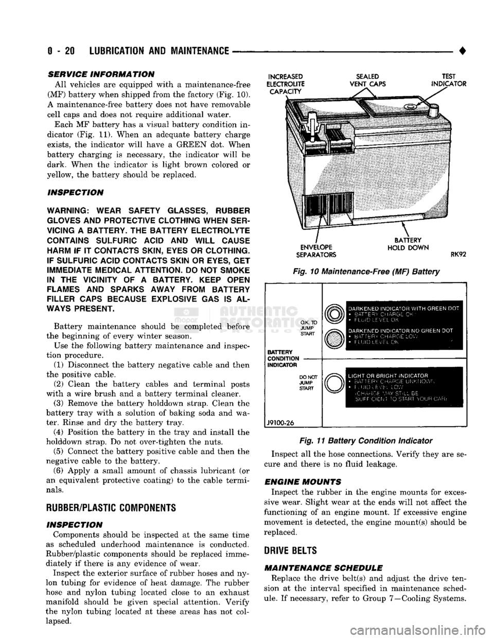
(MF) battery when shipped from the factory (Fig. 10).
A maintenance-free battery does not have removable
cell caps and does not require additional water. Each MF battery has a visual battery condition in
dicator (Fig. 11). When an adequate battery charge
exists,
the indicator will have a GREEN dot. When
battery charging is necessary, the indicator will be dark. When the indicator is light brown colored or
yellow, the battery should be replaced.
INSPECTION
WARNING; WEAR SAFETY
GLASSES,
RUBBER
GLOVES
AND
PROTECTIVE CLOTHING WHEN SER
VICING
A
BATTERY.
THE
BATTERY ELECTROLYTE CONTAINS SULFURIC ACID
AND
WILL CAUSE HARM
IF IT
CONTACTS SKIN, EYES
OR
CLOTHING.
IF SULFURIC ACID CONTACTS SKIN
OR
EYES,
GET
IMMEDIATE MEDICAL ATTENTION.
DO
NOT
SMOKE
IN
THE
VICINITY
OF A
BATTERY. KEEP OPEN
FLAMES
AND
SPARKS AWAY FROM BATTERY
FILLER CAPS BECAUSE EXPLOSIVE
GAS IS AL
WAYS
PRESENT.
Battery maintenance should be completed before
the beginning of every winter season.
Use the following battery maintenance and inspec
tion procedure. (1) Disconnect the battery negative cable and then
the positive cable.
(2) Clean the battery cables and terminal posts
with a wire brush and a battery terminal cleaner. (3) Remove the battery holddown strap. Clean the
battery tray with a solution of baking soda and wa
ter. Rinse and dry the battery tray.
(4) Position the battery in the tray and install the
holddown strap. Do not over-tighten the nuts.
(5) Connect the battery positive cable and then the
negative cable to the battery.
(6) Apply a small amount of chassis lubricant (or
an equivalent protective coating) to the cable termi
nals.
RUBBER/PLASTIC
COMPONENTS
INSPECTION Components should be inspected at the same time
as scheduled underhood maintenance is conducted.
Rubber/plastic components should be replaced imme diately if there is any evidence of wear. Inspect the exterior surface of rubber hoses and ny
lon tubing for evidence of heat damage. The rubber
hose and nylon tubing located close to an exhaust
manifold should be given special attention. Verify
the nylon tubing located at these areas has not col lapsed.
INCREASED
ELECTROUTE CAPACITY
SEALED
VENT
CAPS TEST
INDICATOR ENVELOPE
SEPARATORS
BATTERY
HOLD DOWN
RK92
Fig. 10 Maintenance-Free (MF)
Battery
O.K. TO
JUMP START
BATTERY
CONDITION
INDICATOR
J9100-26
DARKENED
INDICATOR
WITH
GREEN
DOT
•
BATTERY CHARGE
OK '
•
FLUID LEVEL
OK
DARKENED
INDICATOR
NO
GREEN
DOT
•
BATTERY CHARGE
LOW
FLUID LEVEL
OK
LIGHT
OR
BRIGHT INDICATOR
•
BATTERY CHARGE UNKNOWN
•
FLUID uEv'EL
LOW
(CHARGE
MAY
STILL
BE
SUFFICIENT
TO
START YOUR
CAR)
Fig. 11
Battery
Condition Indicator
Inspect all the hose connections. Verify they are se
cure and there is no fluid leakage.
ENGINE MOUNTS Inspect the rubber in the engine mounts for exces
sive wear. Slight wear at the ends will not affect the
functioning of an engine mount. If excessive engine
movement is detected, the engine mount(s) should be
replaced.
DRIVE
BELTS
MAINTENANCE SCHEDULE Replace the drive belt(s) and adjust the drive ten
sion at the interval specified in maintenance sched
ule.
If necessary, refer to Group 7—Cooling Systems.
Page 42 of 1502
•
LUBRICATION
AND
MAINTENANCE
0 - 23 GEAR SHIFTER BOOTS
Inspect the shifter boots periodically for stone and
heat damage. Replace, if necessary.
SEVERE DRIVING CONDITIONS The interval between the transmission drain and
refill maintenance should be decreased to:
• NV4500 manual transmission—every 29 000 km (18,000 miles)
• Automatic transmission—every 19 000 km (12,000
miles)
A severe driving condition includes:
• Extended operation with heavy cargo loads
• Driving in deep mud or snow
• Off-road operation (4WD)
• Trailer towing
• Operation as a commercial vehicle
• Snow plowing
MANUAL TRANSMISSIONS
INSPECTION/LUBE
OIL
LEVEL
The transmission should be checked for leaks when
other service is necessary under the vehicle. To check
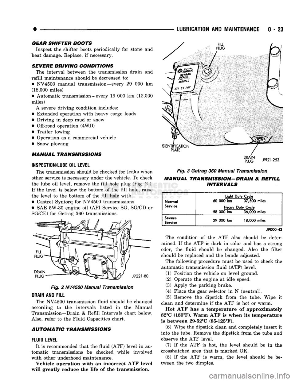
the lube oil level, remove the fill hole plug (Fig. 2 ). If the level is below the bottom of the fill hole, raise
the level to the bottom of the fill hole with:
• Castrol Syntorq for NV4500 transmissions
• SAE 5W-30 engine oil (API Service SG, SG/CD or
SG/CE) for Getrag 360 transmissions.
Fig.
2 NV4500 Manual
Transmission
DRAIN
AND
FILL
The NV4500 transmission fluid should be changed
according to the intervals listed in the Manual
Transmission—Drain & Refill Intervals chart below.
Also,
refer to the Fluid Capacities chart.
AUTOMATIC TRANSMISSIONS
FLUID
LEWEL
It is recommended that the fluid (ATF) level in au
tomatic transmissions be checked while involved
with other underhood maintenance.
Vehicle operation with an incorrect ATF level
will greatly reduce the life of the transmission.
Fig.
3 Getrag 360 Manual
Transmission
MANUAL TRANSMISSION-DRAIN & REFILL INTERVALS
Normal
Service
Light
Duty
Cycle
60 000
km
37,500
miles
Heavy
Duty
Cycle
58 000
km
36,000
miles
Severe
Service
29 000
km
18,000
miles
J9000-43
The condition of the ATF also should be deter
mined. If the ATF is dark in color and has a strong odor, the fluid should be changed. Also the filter should be replaced and the bands adjusted.
The following procedure must be used to check the
automatic transmission fluid (ATF) level.
(1) Position the vehicle on level ground.
(2) Operate the engine at idle speed.
(3) Apply the parking brake.
(4) Place the gear selector in N (neutral).
(5) Remove the dipstick from the tube. Wipe it
clean and determine if the ATF is hot or warm.
Hot ATF has a temperature of approximately
82°C (180°F). Warm ATF is when its temperature
is between 29-52°C (85-125°F). (6) Wipe the dipstick clean and completely insert it
into the tube. Remove the dipstick from the tube and
observe the ATF level.
(7) If the ATF is hot, the level should be in the
crosshatched area that is marked OK.
(8) If the ATF is warm, the level should be be
tween the two dimples.
Page 43 of 1502
0
- 24
LUBRICATION
AND
MAINTENANCE
•
CAUTION:
Do not
overfill
the
transmission.
(9) Adjust
the
level
of the ATF
accordingly.
It
is
important
to use the
correct fluid
in an
automatic transmission. MOPAR®ATF PLUS
(ATF Type
7176)
should
be
used. Dexron®
II
ATF
can be
used
if the
recommended fluid
is not
available,
(10) Insert
the
dipstick into
the
tube.
DRAIN, FILTER CHANGE, BAND ADJUSTMENT AND REFILL
The chart below lists
the
intervals
at
which
the
transmission should
be
serviced. Also, refer
to the
Fluid Capacities chart
for
fill capacity.
AUTOMATIC TRANSMISSION SERVICE
IN-
TERVALS
Normal
Usage
Light
Duty
Cycle
60 000
km
37,500
miles
Heavy
Duty
Cycle
38
000 km 24,000
miles
Severe
Usage
19 000 km 12,000
miles
J9100-19
It
is
very important
to use the
correct fluid
in
an automatic transmission. MOPAR®ATF PLUS
(ATF Type
7176)
should
be
used.
An
equivalent
Dexron®
II ATF
could
be
used only
if the
recom
mended fluid
is not
available.
The torque converter does
not
have
a
drain plug.
No attempt should
be
made
to
drain
the
converter.
Refer
to
Group
21
—Transmissions
for
transmission
drain
and
refill procedures.
TRANSFER
CASE
(4WD
VEHICLES)
INSPECTION The NP205
and
NP241 transfer cases fluid level
should
be
checked whenever maintenance
is
neces
sary under
the
vehicle.
FLUID
LEVEL
The vehicle must
be
level when
the
fluid level
is checked.
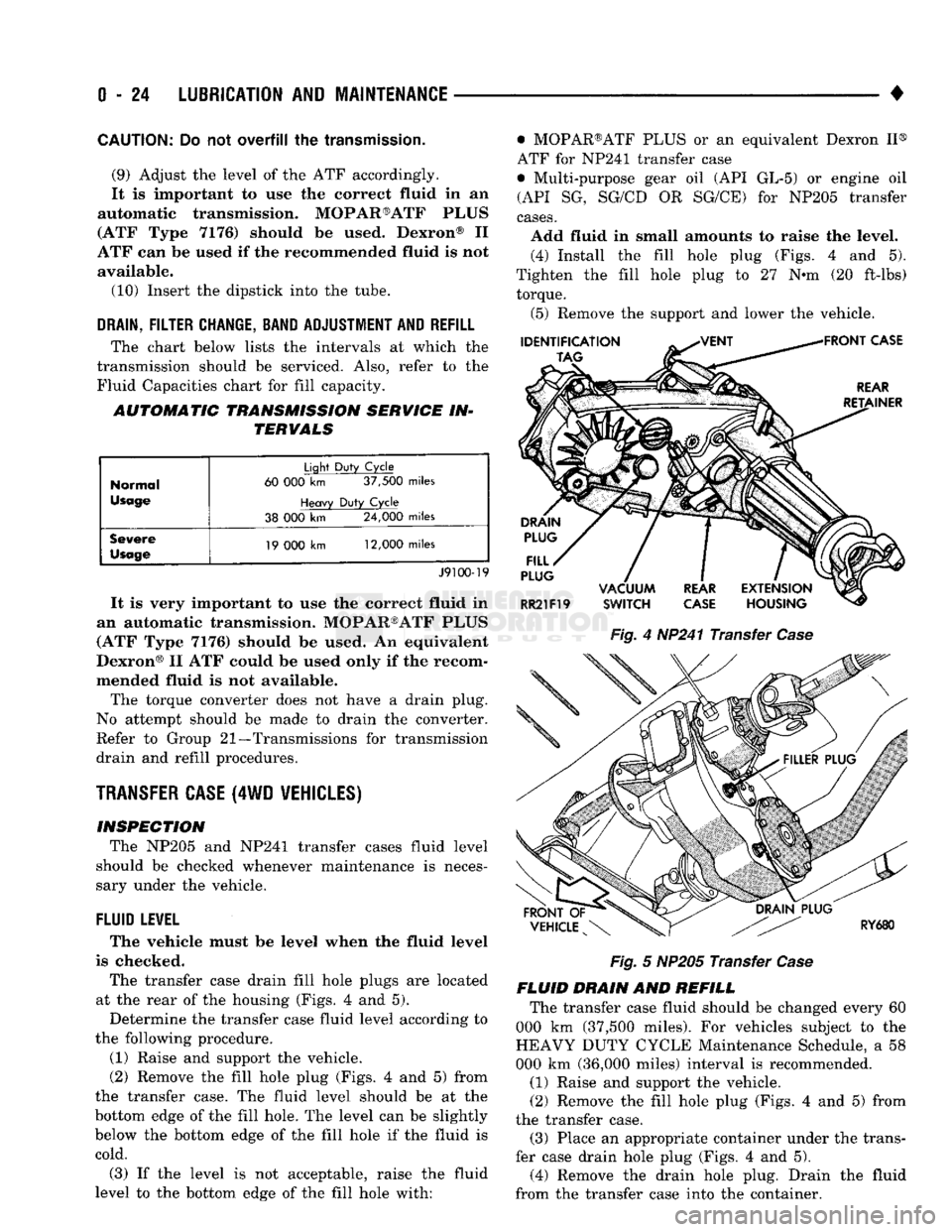
The transfer case drain fill hole plugs
are
located
at
the
rear
of the
housing (Figs.
4 and 5).
Determine
the
transfer case fluid level according
to
the following procedure.
(1) Raise
and
support
the
vehicle.
(2) Remove
the
fill hole plug (Figs.
4 and 5)
from
the transfer case.
The
fluid level should
be at the
bottom edge
of the
fill hole.
The
level
can be
slightly
below
the
bottom edge
of the
fill hole
if the
fluid
is
cold.
(3)
If the
level
is not
acceptable, raise
the
fluid
level
to the
bottom edge
of the
fill hole with: • MOPAR®ATF PLUS
or an
equivalent Dexron
II®
ATF
for
NP241 transfer case
• Multi-purpose gear
oil (API GL-5) or
engine
oil
(API
SG,
SG/CD
OR
SG/CE)
for
NP205 transfer
cases.
Add fluid
in
small amounts
to
raise
the
level. (4) Install
the
fill hole plug (Figs.
4 and 5).
Tighten
the
fill hole plug
to 27 N-m (20
ft-lbs) torque.
(5) Remove
the
support
and
lower
the
vehicle.
Fig.
4
HP241 Transfer
Case
Fig.
5
NP205 Transfer
Case
FLUID DRAIN
AND
REFILL The transfer case fluid should
be
changed every
60
000
km
(37,500 miles).
For
vehicles subject
to the
HEAVY DUTY CYCLE Maintenance Schedule,
a 58
000
km
(36,000 miles) interval
is
recommended.
(1) Raise
and
support
the
vehicle.
(2) Remove
the
fill hole plug (Figs.
4 and 5)
from
the transfer case. (3) Place
an
appropriate container under
the
trans
fer case drain hole plug (Figs.
4 and 5).
(4) Remove
the
drain hole plug. Drain
the
fluid
from
the
transfer case into
the
container.
Page 44 of 1502
•
LUBRICATION
AND
MAINTENANCE
0 - 25
CAUTION:
Do not
over-tighten
the
drain
and fill
hole
plugs.
Over-tightening
can strip the
hole
threads
and/or crack
the
aluminum housing.
(5) Install the drain hole plug (Figs. 4 and 5) in
the transfer case. Tighten the drain hole plug to 27 N*m (20 ft-lbs) torque. (6) Fill the transfer case to the bottom edge of the
fill hole (Figs. 4 and 5) with: • MOPAR®ATF PLUS or an equivalent Dexron II®
ATF for NP241 transfer cases
• Multi-purpose gear oil (API GL-5) or engine oil (API SG, SG/CD or SG/CE) for NP205 transfer cases. (7) Install the fill hole plug (Figs. 4 and 5) in the
transfer case. Tighten the plug to 27 N«m (20 ft-lbs) torque.
(8) Remove the support and lower the vehicle.
FLUID SPECIFICATION
• MOPAR®ATF PLUS or an equivalent Dexron II®
ATF for NP241 transfer cases • Multi-purpose gear oil (API GL-5) or engine oil (API SG, SG/CD or SG/CE) for NP205 transfer cases
NP20I
MULTI-PURPOSE GEAR OIL/ENGINE
OIL
SELECTION
MULTI-PURPOSE GEAR OIL-if the anticipated
minimum temperature will: • Be above 32°C (90°F)-use SAE 140, API GL-5;
• Decrease to as low as -23°C (-10°F)-use SAE 90,
API GL-5; and • Be below -23°C (-10°F)-use SAE 80, API GL-5. ENGINE OIL—if the anticipated minimum tem
perature will be: ® Above 0°C (32°F)-use SAE 50, API SG, SG/CD or
SG/CE;
• Below 0°C (32°F)-use SAE 30, API SG, SG/CD or SG/CE.
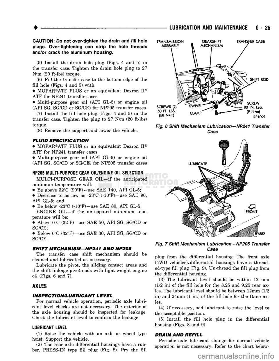
SHIFT MECHANISM-NP241 AND NP205 The transfer case shift mechanism should be
cleaned and lubricated as necessary.
Lubricate the pivot, the sliding contact areas and
the shift linkage pivot ends with light-weight engine oil (Figs. 6 and 7).
AXLES
INSPECTION/LUBRICANT LEVEL For normal vehicle operation, periodic axle lubri
cant level checks are not necessary. The exterior of
the axle housing should be inspected for leakage. Check the lubricant level to confirm the leakage.
LUBRICANT LEVEL
(1) Raise the vehicle with an axle or wheel type
hoist. Support the vehicle.
(2) The rear axle differential housings have a rub
ber, PRESS-IN type fill plug (Fig. 8). Pry the fill
TRANSMISSION
ASSEMBLY
GEARSHIFT
MECHANISM TRANSFER CASE
SCREWS
(2)
50
FT. LBS.
(68 N*m)
CLAMP
SHIFT
ROD
SCREW
80 IN.
LBS.
(9 N*m)
RP1091
Fig.
6 Shift
Mechanism
Lubrication—NP241 Transfer
Case
Fig.
RY682
7 Shift
Mechanism
Lubrication—NP205 Transfer
Case
plug from the differential housing. The front axle (4WD vehicles)*differential housings have a thread
ed-type fill plug (Fig. 9). Un-thread the fill plug from
the differential housing.
(3) The lubricant level should be within 12 mm
(1/2 in) of the fill hole for the 8.25 and 9.25 rear ax
les.
The lubricant level should be between 12mm (1/2
in) and 24mm (1 in.) of the fill hole for the Dana ax
les.
(4) If necessary, add lubricant to raise the level to
the acceptable position.
(5) Install the fill hole plug in the differential
housing (Figs. 8 and 9).
DRAIN
AND
REFILL
Periodic axle lubricant change for normal vehicle
operation is not necessary. Refer to the chart below-