1993 DODGE TRUCK engine
[x] Cancel search: enginePage 70 of 1502
•
FRONT
SUSPENSION
AND
AXLE
2 - 17
MODEL
44
FRONT
AXLE
INDEX
page
Axle Shaft
and
U-Joint
Service
23
Complete Axle Removal/Installation
31
Differential
Assembly
35
Differential
Disassembly
. 32
Drain
and Refill
19
General
Information
17
Hub,
Spindle
and
Axle Shaft
20
Intermediate
Axle Shaft
30
Lubricant
17
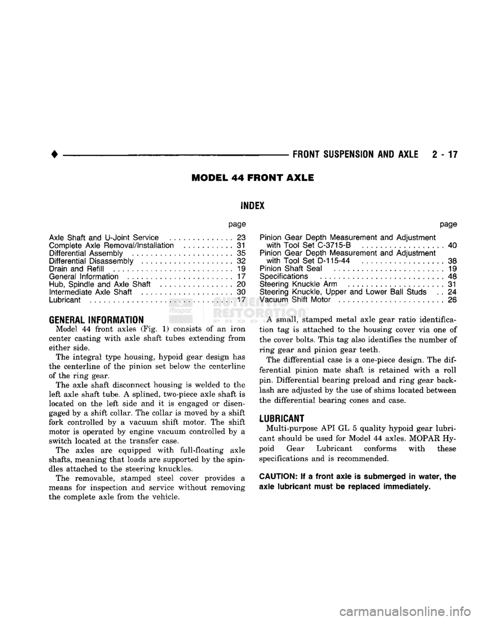
GENERAL
INFORMATION
Model
44
front axles
(Fig. 1)
consists
of an
iron
center casting with axle shaft tubes extending from
either side. The integral type housing, hypoid gear design
has
the centerline
of the
pinion
set
below
the
centerline of
the
ring gear. The axle shaft disconnect housing
is
welded
to the
left axle shaft tube.
A
splined, two-piece axle shaft
is
located
on the
left side
and it is
engaged
or
disen
gaged
by a
shift collar.
The
collar
is
moved
by a
shift
fork controlled
by a
vacuum shift motor.
The
shift motor
is
operated
by
engine vacuum controlled
by a
switch located
at the
transfer case. The axles
are
equipped with full-floating axle
shafts,
meaning that loads
are
supported
by the
spin
dles attached
to the
steering knuckles. The removable, stamped steel cover provides
a
means
for
inspection
and
service without removing
the complete axle from
the
vehicle.
page
Pinion Gear Depth Measurement
and
Adjustment
with
Tool
Set
C-3715-B
40
Pinion Gear Depth Measurement
and
Adjustment
with
Tool
Set
D-115-44
... 38
Pinion Shaft Seal
19
Specifications
48
Steering Knuckle
Arm
31
Steering Knuckle, Upper
and
Lower Ball Studs
. . 24
Vacuum
Shift Motor
26
A small, stamped metal axle gear ratio identifica
tion
tag is
attached
to the
housing cover
via one of
the cover bolts. This
tag
also identifies
the
number
of
ring gear
and
pinion gear teeth.
The differential case
is a
one-piece design.
The dif
ferential pinion mate shaft
is
retained with
a
roll
pin. Differential bearing preload
and
ring gear back lash
are
adjusted
by the use of
shims located between
the differential bearing cones
and
case.
LUBRICANT
Multi-purpose
API GL 5
quality hypoid gear lubri
cant should
be
used
for
Model
44
axles. MOPAR
Hy
poid Gear Lubricant conforms with these specifications
and is
recommended.
CAUTION:
If a
front axle
is
submerged
in
water,
the
axle lubricant must
be
replaced immediately.
Page 72 of 1502
FRONT
SUSPENSION
AND
AXLE
2 - 19
DRAIN
AND
REFILL
(1) Drive the vehicle until the gear lubricant
reaches normal operating temperature. (2) Raise and support the vehicle.
(3) Remove the lubricant fill hole plug from the
differential housing cover.
(4) Remove the differential housing cover. Allow
the original lubricant to completely drain from the
housing and axle shaft tubes.
(5) With standard differential, clean the differen
tial and the housing cavity with a flushing oil (or light engine oil). This will remove the residual lubricant and foreign matter. Do not use water, steam,
kerosene or gasoline for flushing. (6) Scrape the residual gasket from the housing
and cover mating surfaces. Clean the mating sur
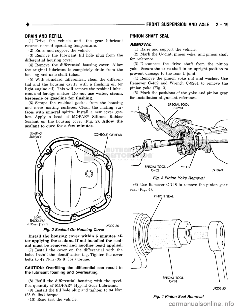
faces with mineral spirits. Install a new cover gas ket. Apply a bead of MOPAR® Silicone Rubber Sealant on the housing cover (Fig. 2). Allow the
sealant to cure for a few minutes.
SEALING
SURFACE
CONTOUR
OF
BEAD
BEAD
THICKNESS
6.35mm
(1/4")
J9302-30
Fig.
2 Sealant On
Housing
Cover
Install the housing cover within 5 minutes af
ter applying the sealant. If not installed the seal ant must be removed and another bead applied.
(7) Install the cover on the differential with the
bolts.
Install the identification tag. Tighten the cover
bolts to 47 Nnn (35 ft. lbs.) torque.
CAUTION:
Overfilling the
differential
can result in
the lubricant
foaming
and overheating.
(8) Refill the differential housing with the speci
fied quantity of MOPAR® Hypoid Gear Lubricant.
(9) Install the fill hole plug and tighten to 34 N#m
(25 ft. lbs.) torque.
(10) Road test the vehicle.
PINION
SHAFT
SEAL
REMOVAL
(1) Raise and support the vehicle.
(2) Mark the U-joint, pinion yoke, and pinion shaft
for reference.
(3) Disconnect the drive shaft from the pinion
yoke. Secure the drive shaft in an upright position to prevent damage to the rear U-joint.
(4) Remove the pinion yoke nut and washer. Use
Remover C-452 and Wrench C-3281 to remove the
pinion yoke (Fig. 3).
(5) Mark the positions of the yoke and pinion gear
for installation alignment reference.
SPECIAL
TOOL
C-3281
SPECIAL
TOOL
C-452
J9102-31
Fig.
3
Pinion
Yoke
Removal
(6) Use Remover C-748 to remove the pinion gear
seal (Fig. 4).
PINION
SEAL
SPECIAL
TOOL
C-748
Fig.
4
Pinion
Seal
Removal
J9203-55
Page 80 of 1502
NUT
LEFT
ENGINE
MOUNT
LEFT
ENGINE
MOUNT
NUT
ANDyv
WASHER
VIEW
IN DIRECTION
OF ARROW
W
TORQUE
LET. POUNDS NEWTON
METRES
FULLY SEATED
HAND TIGHTENED
55
IN.
6
15 FT. 20
CLIP
ALIGN
WHITE
TAPE
TO END OF CLIP
VIEW
IN DIRECTION
OF
ARROW Z
WITH
V-6
CLIP.
SHIFT
MOTOR
ROUTE HOSE
TO
REAR
OF
DISTRIBUTOR
VIEW
IN DIRECTION
OF ARROW
Z
VIEW
IN
DIRECTION OF ARROW X
J9102-61
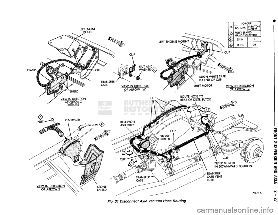
Fig. 31 Disconnect
Axle
Vacuum Hose Routing
Page 81 of 1502
2 - 28
FRONT
SUSPENSION
AND
AXLE
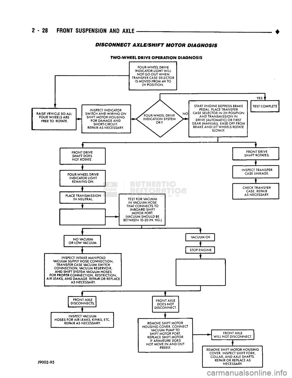
DISCONNECT
AXLE/SHIFT
MOTOR
DIAGNOSIS
TWO-WHEEL DRIVE
OPERATION
DIAGNOSIS
FOUR-WHEEL DRIVE
INDICATOR
LIGHT
WILL NOT GO OUT WHEN
TRANSFER CASE SELECTOR
IS
MOVED FROM 4H TO 2H POSITION.
RAISE
VEHICLE SO ALL FOUR WHEELS ARE
FREE
TO ROTATE. INSPECT INDICATOR
SWITCH AND WIRING ON SHIFT MOTOR HOUSING FOR DAMAGE AND SHORT-CIRCUIT.
REPAIR
AS NECESSARY.
YES
i
START ENGINE DEPRESS BRAKE
PEDAL.
PLACE TRANSFER
CASE
SELECTOR IN 2H POSITION AND TRANSMISSION IN
DRIVE
(AUTOMATIC)
OR FIRST
GEAR
(MANUAL). EASE OFF FROM
BRAKE
AND LET WHEELS ROTATE SLOWLY. TEST COMPLETE
FRONT DRIVE SHAFT DOES
NOT ROTATE. FRONT DRIVE
SHAFT ROTATES.
FOUR-WHEEL DRIVE INDICATOR
LIGHT
REMAINS
ON. INSPECT TRANSFER
CASE
LINKAGE.
PLACE
TRANSMISSION IN NEUTRAL. TEST FOR VACUUM
IN VACUUM HOSE
THAT
CONNECTS TO INBOARD SHIFT MOTOR PORT.
(VACUUM SHOULD BE
BETWEEN 10-20 IN. HG.)
CHECK
TRANSFER
CASE.
REPAIR
AS
NECESSARY.
NO VACUUM
OR LOW VACUUM. VACUUM OK
INSPECT INTAKE MANIFOLD
VACUUM SUPPLY HOSE CONNECTION,
TRANSFER CASE VACUUM SWITCH
CONNECTION, VACUUM RESERVOIR, AND SHIFT SYSTEM VACUUM HOSES
FOR PROPER CONNECTION, RESTRICTION,
AIR LEAKS, AND DAMAGE. REPAIR OR REPLACE
AS
NECESSARY. STOP ENGINE
—r~
FRONT AXLE
DISCONNECTS.
INSPECT VACUUM
HOSES
FOR AIR LEAKS, KINKS, ETC.
REPAIR
AS NECESSARY. FRONT AXLE
DOES
NOT
DISCONNECT.
REMOVE SHIFT MOTOR
HOUSING COVER. CONNECT VACUUM PUMP TO
SHIFT MOTOR PORT.
REPLACE
SHIFT MOTOR
IF ARMATURE DOES
NOT MOVE IN AND OUT FREELY. FRONT AXLE
WILL NOT DISCONNECT.
J9002-95
REMOVE SHIFT MOTOR HOUSING
COVER. INSPECT SHIFT FORK, COLLAR, AND AXLE SHAFTS.
REPAIR
OR REPLACE AS
NECESSARY
Page 82 of 1502
FRONT
SUSPENSION AND
AXLE
2 - 29
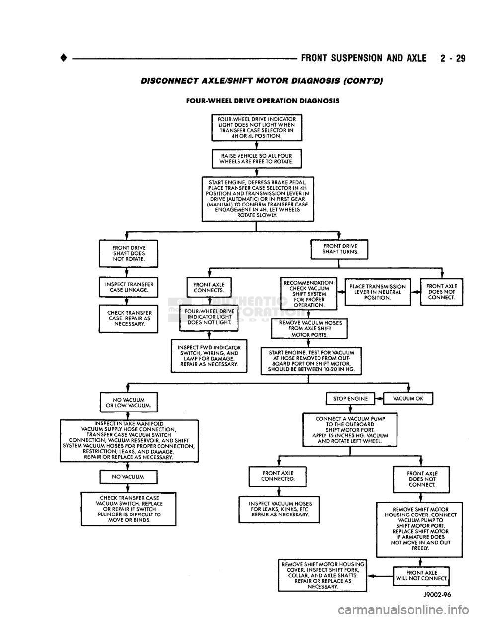
DISCONNECT AXLE/SHIFT MOTOR DIAGNOSIS
(CONT'D)
FOUR-WHEEL
DRIVE
OPERATION
DIAGNOSIS
FOUR-WHEEL DRIVE INDICATOR
LIGHT
DOES NOT
LIGHT
WHEN TRANSFER CASE SELECTOR IN 4H OR 4L POSITION.
RAISE
VEHICLE SO ALL FOUR
WHEELS ARE FREE TO ROTATE.
START ENGINE, DEPRESS BRAKE PEDAL.
PLACE
TRANSFER CASE SELECTOR IN 4H
POSITION AND TRANSMISSION LEVER IN DRIVE
(AUTOMATIC)
OR IN FIRST GEAR
(MANUAL) TO CONFIRM TRANSFER CASE ENGAGEMENT IN 4H. LET WHEELS ROTATE SLOWLY.
FRONT DRIVE SHAFT DOES
NOT ROTATE. FRONT DRIVE
SHAFT TURNS.
INSPECT TRANSFER
CASE
LINKAGE.
CHECK
TRANSFER
CASE.
REPAIR AS
NECESSARY.
FRONT AXLE
CONNECTS.
FOUR-WHEEL DRIVE INDICATOR
LIGHT
DOES
NOT LIGHT.
INSPECT FWD INDICATOR SWITCH, WIRING, AND
LAMP FOR DAMAGE.
REPAIR
AS NECESSARY. RECOMMENDATION:
CHECK
VACUUM SHIFT SYSTEM FOR PROPER
OPERATION.
PLACE
TRANSMISSION
LEVER IN NEUTRAL POSITION. FRONT AXLE
DOES
NOT
CONNECT.
REMOVE VACUUM HOSES FROM AXLE SHIFT MOTOR PORTS.
START ENGINE. TEST FOR VACUUM AT HOSE REMOVED FROM
OUT
BOARD
PORT ON SHIFT MOTOR,
SHOULD BE BETWEEN 10-20 IN HG.
NO VACUUM
OR LOW VACUUM. STOP ENGINE
H VACUUM OK
INSPECT INTAKE MANIFOLD
VACUUM SUPPLY HOSE CONNECTION, TRANSFER CASE VACUUM SWITCH
CONNECTION, VACUUM RESERVOIR, AND SHIFT
SYSTEM VACUUM HOSES FOR PROPER CONNECTION, RESTRICTION, LEAKS, AND DAMAGE.
REPAIR
OR REPLACE AS NECESSARY. CONNECT A VACUUM PUMP
TO THE OUTBOARD
SHIFT MOTOR PORT.
APPLY 15 INCHES HG. VACUUM AND ROTATE LEFT WHEEL.
NO VACUUM FRONT AXLE
CONNECTED.
CHECK
TRANSFER CASE
VACUUM SWITCH. REPLACE OR REPAIR IF SWITCH
PLUNGER IS DIFFICULT TO MOVE OR BINDS. FRONT AXLE
DOES
NOT
CONNECT.
INSPECT VACUUM HOSES FOR LEAKS, KINKS, ETC.
REPAIR
AS NECESSARY. REMOVE SHIFT MOTOR
HOUSING COVER. CONNECT VACUUM PUMP TO
SHIFT MOTOR PORT.
REPLACE
SHIFT MOTOR
IF ARMATURE DOES
NOT MOVE IN AND OUT FREELY. REMOVE SHIFT MOTOR HOUSING
COVER. INSPECT SHIFT FORK, COLLAR, AND AXLE SHAFTS.
REPAIR
OR REPLACE AS
NECESSARY.
*
REMOVE SHIFT MOTOR HOUSING
COVER. INSPECT SHIFT FORK, COLLAR, AND AXLE SHAFTS.
REPAIR
OR REPLACE AS
NECESSARY.
FRONT AXLE
WILL NOT CONNECT.
REMOVE SHIFT MOTOR HOUSING
COVER. INSPECT SHIFT FORK, COLLAR, AND AXLE SHAFTS.
REPAIR
OR REPLACE AS
NECESSARY.
FRONT AXLE
WILL NOT CONNECT.
REMOVE SHIFT MOTOR HOUSING
COVER. INSPECT SHIFT FORK, COLLAR, AND AXLE SHAFTS.
REPAIR
OR REPLACE AS
NECESSARY.
J9002-96
Page 104 of 1502
FRONT
SUSPENSION
AND
AXLE
2 - 51
LUBRICANT
Multi-purpose API GL 5 quality hypoid gear lubri
cant should be used for Model 60 axles. MOPAR Hy
poid Gear Lubricant conforms to these specifications and is recommended.
CAUTION:
If a front axle is
submerged
in
water,
the
axle lubricant
must
be replaced immediately.
DRAIN AND REFILL
(1) Drive the vehicle until the gear lubricant
reaches normal operating temperature. (2) Raise and support the vehicle.
(3) Remove the lubricant fill hole plug from the
differential housing cover. (4) Remove the differential housing cover. Allow
the original lubricant to completely drain from the
housing and axle shaft tubes. (5) With standard differential, clean the differen
tial and the housing cavity with a flushing oil (or light engine oil). This will remove the residual lubricant and foreign matter. Do not use water, steam,
kerosene or gasoline for flushing. (6) Scrape the residual gasket from the housing
and cover mating surfaces. Clean the mating sur
faces with mineral spirits. Install a new cover gas
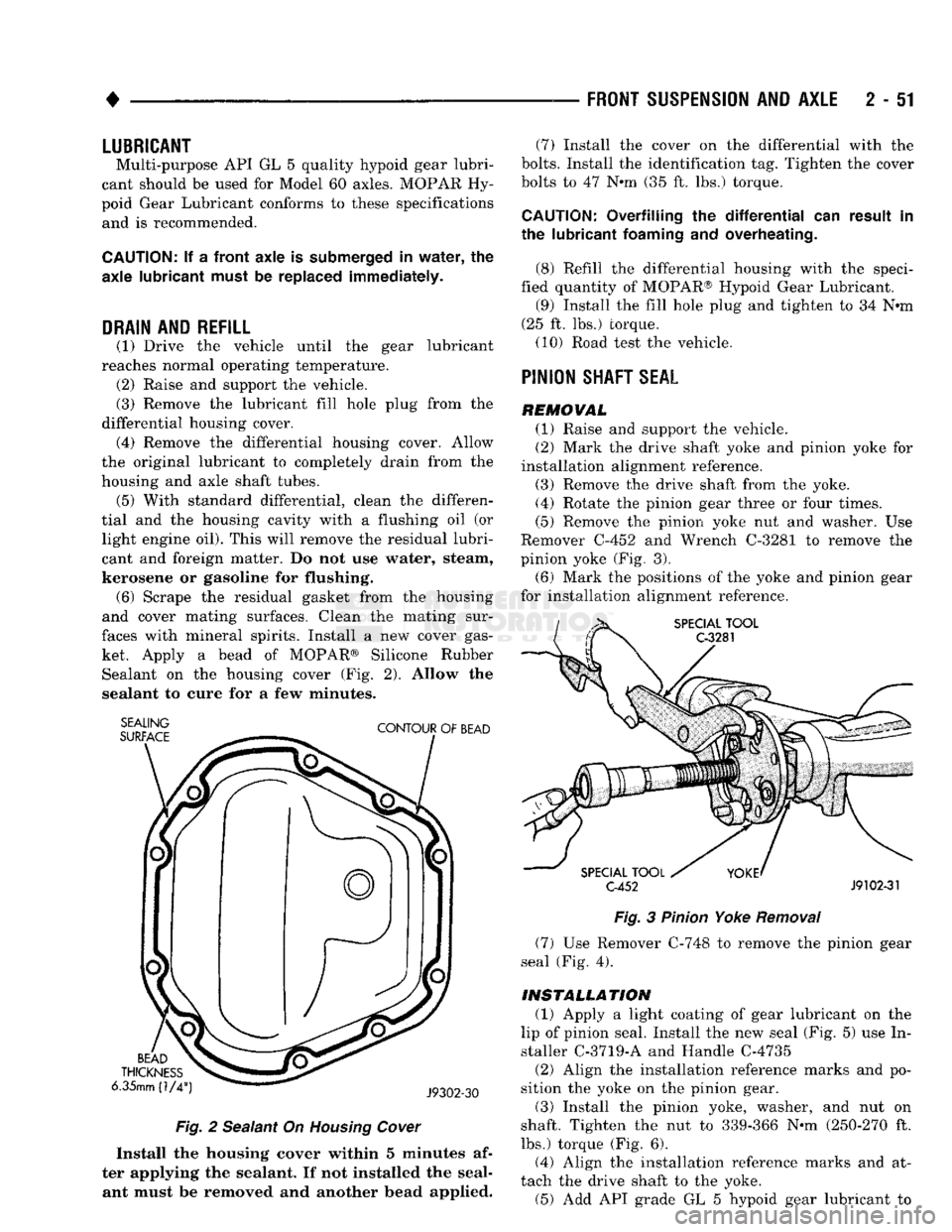
ket. Apply a bead of MOPAR® Silicone Rubber Sealant on the housing cover (Fig. 2). Allow the
sealant to cure for a few minutes.
SEALING
SURFACE
CONTOUR
OF
BEAD
BEAD
THICKNESS
6.35mm (1/4
J9302-30
Fig.
2 Sealant On
Housing
Cover
Install the housing cover within 5 minutes af
ter applying the sealant. If not installed the seal ant must be removed and another bead applied. (7) Install the cover on the differential with the
bolts.
Install the identification tag. Tighten the cover
bolts to 47 Nnn (35 ft. lbs.) torque.
CAUTION:
Overfilling the
differential
can result in
the lubricant
foaming
and overheating.
(8) Refill the differential housing with the speci
fied quantity of MOPAR® Hypoid Gear Lubricant. (9) Install the fill hole plug and tighten to 34 N«m
(25 ft. lbs.) torque. (10) Road test the vehicle.
PINION
SHAFT
SEAL
REMOVAL (1) Raise and support the vehicle.
(2) Mark the drive shaft yoke and pinion yoke for
installation alignment reference.
(3) Remove the drive shaft from the yoke.
(4) Rotate the pinion gear three or four times.
(5) Remove the pinion yoke nut and washer. Use
Remover C-452 and Wrench C-3281 to remove the
pinion yoke (Fig. 3).
(6) Mark the positions of the yoke and pinion gear
for installation alignment reference.
SPECIAL
TOOL
C-3281
SPECIAL
TOOL
C-452
J9102-31
Fig.
3
Pinion
Yoke
Removal
(7) Use Remover C-748 to remove the pinion gear
seal (Fig. 4).
INSTALLATION
(1) Apply a light coating of gear lubricant on the
lip of pinion seal. Install the new seal (Fig. 5) use In
staller C-3719-A and Handle C-4735
(2) Align the installation reference marks and po
sition the yoke on the pinion gear.
(3) Install the pinion yoke, washer, and nut on
shaft. Tighten the nut to 339-366 N-m (250-270 ft.
lbs.) torque (Fig. 6).
(4) Align the installation reference marks and at
tach the drive shaft to the yoke. (5) Add API grade GL 5 hypoid gear lubricant to
Page 135 of 1502
3
- 6
REAR SUSPENSION
AND
AXLE
•
NUT PIPE
SOCKET
WRENCH
(DRIVER)
FLAT
THREADED
WASHER
ROD
J8917-20
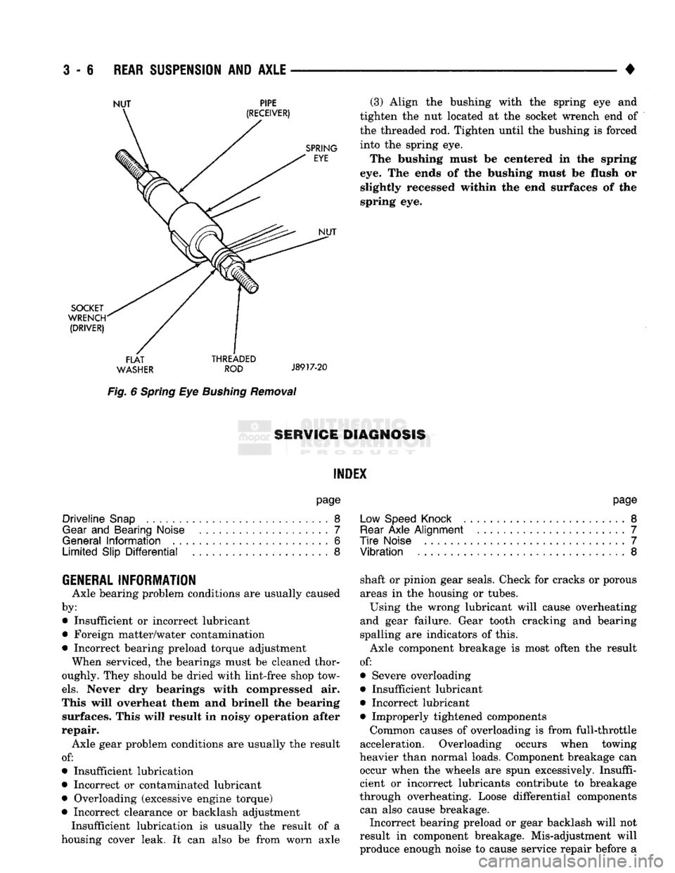
Fig.
6
Spring
Eye
Bushing
Removal
(3) Align
the
bushing with
the
spring
eye and
tighten
the nut
located
at the
socket wrench
end of
the threaded
rod.
Tighten until
the
bushing
is
forced into
the
spring
eye.
The bushing must
be
centered
in the
spring
eye.
The
ends
of the
bushing must
be
flush
or
slightly recessed within
the end
surfaces
of the
spring
eye.
8ERW1GE DIAGNOSIS
INDEX
page
Driveline
Snap
8
Gear
and
Bearing Noise
7
General
Information
6
Limited
Slip
Differential
8
page
Low Speed Knock
.........................
8
Rear
Axle
Alignment
.......................
7
Tire
Noise
7
Vibration
8
GENERAL INFORMATION
Axle bearing problem conditions
are
usually caused
by: • Insufficient
or
incorrect lubricant
• Foreign matter/water contamination
• Incorrect bearing preload torque adjustment When serviced,
the
bearings must
be
cleaned thor
oughly. They should
be
dried with lint-free shop tow
els.
Never
dry
bearings with compressed
air.
This will overheat them
and
brinell
the
bearing surfaces. This will result
in
noisy operation after
repair. Axle gear problem conditions
are
usually
the
result
of:
• Insufficient lubrication
• Incorrect
or
contaminated lubricant
• Overloading (excessive engine torque)
• Incorrect clearance
or
backlash adjustment Insufficient lubrication
is
usually
the
result
of a
housing cover leak.
It can
also
be
from worn axle shaft
or
pinion gear seals. Check
for
cracks
or
porous
areas
in the
housing
or
tubes.
Using
the
wrong lubricant will cause overheating
and gear failure. Gear tooth cracking
and
bearing
spalling
are
indicators
of
this.
Axle component breakage
is
most often
the
result
of:
• Severe overloading
• Insufficient lubricant
• Incorrect lubricant • Improperly tightened components
Common causes
of
overloading
is
from full-throttle
acceleration. Overloading occurs when towing
heavier than normal loads. Component breakage
can
occur when
the
wheels
are
spun excessively. Insuffi
cient
or
incorrect lubricants contribute
to
breakage
through overheating. Loose differential components can also cause breakage. Incorrect bearing preload
or
gear backlash will
not
result
in
component breakage. Mis-adjustment will
produce enough noise
to
cause service repair before
a
Page 137 of 1502
3
- 8
REAR SUSPENSION
AND
AXLE
• level. Where axle bearing damage is slight, the noise
is usually not noticeable at speeds above 30 mph.
LOW SPEED KNOCK
Low speed knock is generally caused by a worn
U-joint or by worn side-gear thrust washers. A worn
pinion gear shaft bore will also cause low speed knock.
VIBRATION
Vibration at the rear of the vehicle is usually
caused by a:
• Damaged drive shaft
• Missing drive shaft balance weight
• Worn, out-of-balance wheel and tires
• Loose wheel lug nuts
• Worn U-joint • Loose spring U-bolts
• Loose/broken rear springs or shackles
• Damaged axle shaft bearings
• Loose pinion gear nut
• Excessive pinion yoke run out
• Bent axle shaft Check for loose or damaged front-end components
or engine/transmission mounts. These components
can contribute to what appears to be a rear-end vi
bration. Do not overlook engine accessories, brackets and drive belts. All driveline components should be examined be
fore starting any repair. Refer to Group 22, Wheels and Tires for additional
information.
DRIVELINE SNAP
A snap or clunk noise when the vehicle is shifted
into gear (or the clutch engaged), can be caused by: • High engine idle speed
• Loose engine/transmission/transfer case mounts
9
Worn U-joints
• Loose spring shackles or U-bolts
• Loose pinion gear nut and yoke
• Excessive ring gear backlash
• Excessive differential side gear-to-case clearance A worn bushing in the transmission extension
housing can also cause noise. The source of a snap or a clunk noise can be deter
mined with the assistance of a helper. Raise the ve
hicle on a hoist with the wheels free to rotate. Instruct the helper to shift the transmission into gear. Listen for the noise, a mechanics stethoscope is
helpful in isolating the source of a noise.
LIMITED
SLIP DIFFERENTIAL
Under normal traction conditions, engine torque is
divided evenly. With low-traction surfaces, engine
torque is transferred to the wheel with the most tire
traction. When diagnosing a limited-slip differential
problem condition, the wheel with the least traction can continue spinning. The most common problem is a chatter noise when
turning corners. Check for incorrect or contaminated lubricant. Replace the gear lubricant if necessary.
• With Sure-Grip differentials add a container of
MOPAR® Hypoid Gear Additive This will correct the condition in most instances. If
the chatter persists, clutch damage could have oc curred. After changing the lubricant, drive the vehicle and
make 10 to 12 slow, figure-eight turns. This maneu
ver will pump lubricant through the clutches.