1993 DODGE TRUCK air filter
[x] Cancel search: air filterPage 752 of 1502
5.9L
(DIESEL) ENGINE
9 - 149
FILTER
BYPASS-
VALVE
OIL COOLER COVER
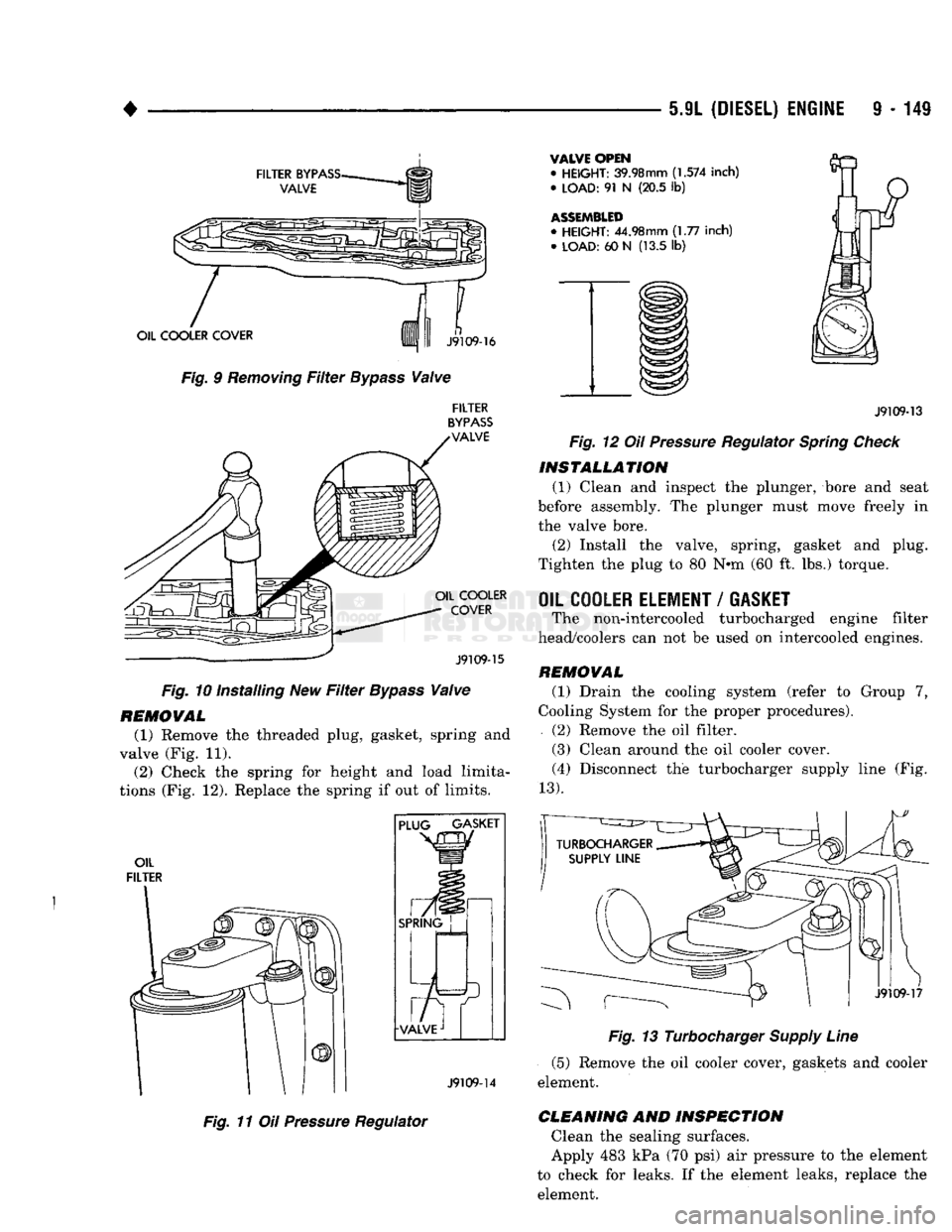
Fig. 9
Removing
Filter
Bypass
Valve
n
J9109-16
FILTER
BYPASS
VALVE OIL COOLER
COVER
J9109-15
Fig. 10 Installing New
Filter
Bypass
Valve
REMOVAL
(1) Remove the threaded plug, gasket, spring and
valve (Fig. 11). (2) Check the spring for height and load limita
tions (Fig. 12). Replace the spring if out of limits.
OIL
FILTER PLUG GASKET
SPRING
J9109-14
Fig. 11 Oil
Pressure
Regulator
VALVE OPEN
•
HEIGHT:
39.98mm
(1.574
inch)
•
LOAD:
91 N (20.5 lb)
ASSEMBLED
•
HEIGHT:
44.98mm (1.77 inch) •
LOAD:
60 N (13.5 lb)
J9109-13
Fig. 12 Oil
Pressure
Regulator
Spring
Check
INSTALLATION
(1) Clean and inspect the plunger, bore and seat
before assembly. The plunger must move freely in
the valve bore.
(2) Install the valve, spring, gasket and plug.
Tighten the plug to 80 N*m (60 ft. lbs.) torque.
OIL COOLER ELEMENT
/
GASKET
The non-intercooled turbocharged engine filter
head/coolers can not be used on intercooled engines.
REMOVAL
(1) Drain the cooling system (refer to Group 7,
Cooling System for the proper procedures).
(2) Remove the oil filter.
(3) Clean around the oil cooler cover. (4) Disconnect the turbocharger supply line (Fig.
13).
J9109-17
Fig. 13 Turbocharger
Supply
Line
(5) Remove the oil cooler cover, gaskets and cooler
element.
CLEANING
AND
INSPECTION
Clean the sealing surfaces.
Apply 483 kPa (70 psi) air pressure to the element
to check for leaks. If the element leaks, replace the element.
Page 756 of 1502
5.9L
(DIESEL)
ENGINE
9-153
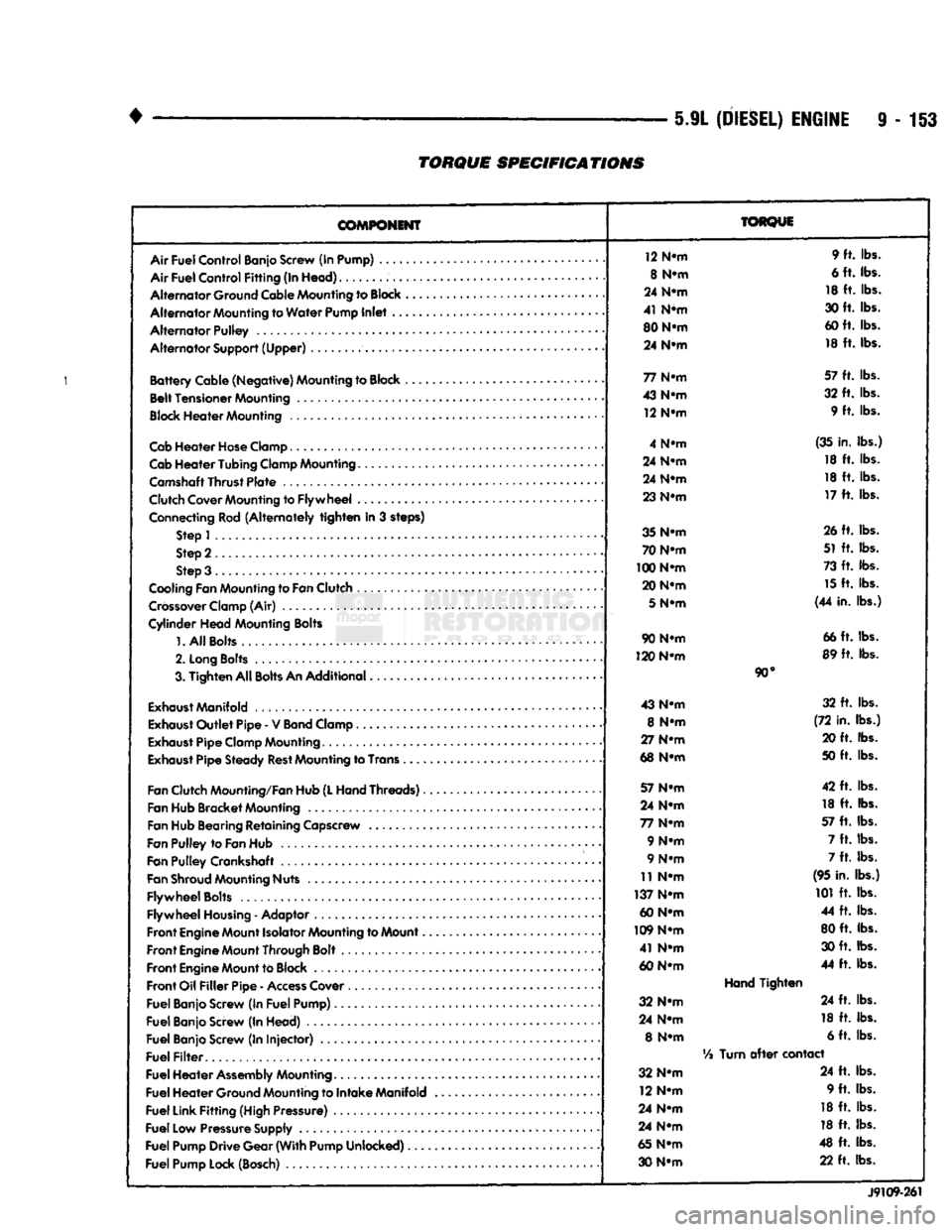
TORQUE
SPECIFICATIONS
COMPONENT
Air
Fuel
Control
Banjo Screw (In Pump) ....
Air
Fuel
Control
Fitting
(In
Head)
Alternator
Ground Cable Mounting to
Block
Alternator
Mounting to
Water
Pump
Inlet
..
Alternator
Pulley
Alternator
Support
(Upper)
Battery
Cable
(Negative)
Mounting to Block ,
Belt
Tensioner
Mounting
Block
Heater
Mounting
Cab
Heater
Hose
Clamp
Cab
Heater
Tubing
Clamp Mounting.......
Camshaft
Thrust
Plate
Clutch Cover Mounting to
Flywheel
...
Connecting Rod
(Alternately
tighten
in 3 steps) Step 1
Step 2
Step 3 .
Cooling Fan Mounting to
Fan
Clutch
Crossover
Clamp (Air)
Cylinder
Head
Mounting Bolts
1.
All
Bolts....
2.
Long
Bolts
.........
3.
Tighten
All
Bolts
An
Additional
Exhaust
Manifold
Exhaust
Outlet
Pipe
- V
Band
Clamp
Exhaust
Pipe
Clamp Mounting
Exhaust
Pipe
Steady
Rest
Mounting to Trans .
Fan
Clutch Mounting/Fan Hub
(L
Hand
Threads)..
Fan Hub
Bracket
Mounting
Fan Hub Bearing
Retaining
Capscrew
Fan
Pulley
to
Fan
Hub
Fan
Pulley
Crankshaft .
Fan
Shroud
Mounting Nuts
Flywheel
Bolts
Flywheel
Housing
- Adaptor
Front
Engine
Mount Isolator Mounting to Mount..
Front
Engine
Mount Through Bolt
Front
Engine
Mount to Block
Front
Oil
Filler
Pipe
-
Access
Cover
Fuel
Banjo Screw (In
Fuel
Pump)
Fuel
Banjo Screw (In
Head)
Fuel
Banjo Screw (In
Injector)
Fuel
Filter
Fuel
Heater
Assembly
Mounting
Fuel
Heater
Ground Mounting to
Intake
Manifold
Fuel
Link
Fitting
(High Pressure)
Fuel
Low Pressure Supply
Fuel
Pump
Drive
Gear
(With
Pump
Unlocked)
Fuel
Pump Lock (Bosch)
TORQUE
12 N-m 9 ft. lbs.
8 N-m 6 ft. lbs.
24 N-m 18 ft. lbs.
41 N*m 30 ft. lbs.
80 N-m 60 ft. lbs.
24 N-m 18 ft. lbs.
77 N-m 57 ft. lbs.
43 N-m 32 ft. lbs.
12 N-m 9 ft. lbs.
4 N-m (35 in. lbs.)
24 N-m 18 ft. lbs.
24 N-m 18 ft. lbs.
23 N-m 17 ft. lbs.
35 N-m 26 ft. lbs.
70 N-m 51 ft. lbs.
100 N-m 73 ft. lbs.
20 N-m 15 ft. lbs.
5
N-m (44 in. lbs.)
90 N-m 66 ft. lbs.
120 N-m 89 ft. lbs.
90°
43 N-m 32 ft. lbs.
8 N-m (72 in. lbs.)
27 N-m 20 ft. lbs.
68 N-m 50 ft. lbs.
57 N-m 42 ft. lbs.
24 N-m 18 ft. lbs.
77 N-m 57 ft. lbs.
9 N-m 7 ft. lbs.
9 N-m 7 ft. lbs.
11 N-m (95 in. lbs.)
137 N-m 101 ft. lbs.
60 N-m 44 ft. lbs.
109 N-m 80 ft. lbs.
41 N-m 30 ft. lbs.
60 N-m 44 ft. lbs.
Hand
Tighten
32 N-m 24 ft. lbs.
24 N-m 18 ft. lbs.
8 N-m 6 ft. lbs.
Vi
Turn
after
contact
32 N-m 24 ft. lbs.
12 N-m 9 ft. lbs.
24 N-m 18 ft. lbs.
24 N-m 18 ft. lbs.
65 N-m 48 ft. lbs.
30 N-m 22 ft. lbs.
J9109-261
Page 800 of 1502
•
FRAME
AND
BUMPERS
13 - 13
POWER
UNIT
DISASSEMBL
Y/INSPECTION
(1) Remove the drain plug (Fig. 9). Drain the unit.
(2) Extend the ram and piston rod completely.
Drain the remaining oil from the cylinder.
(3) Remove the cover locknuts (Fig. 9). Remove the
cover.
(4) Inspect the casting for damage and cracks. In
spect the seal for cuts (Fig. 9).
(5) Remove the ram and the piston. Inspect the ny
lon sleeve, the piston, and the piston follower for ex cessive wear (Fig. 10).
(6) Inspect the cylinder for pitting and scoring in
the bore (Fig. 10).
(7) Inspect the ram for nicks, scratches, and corro
sion (Fig. 10).
(8) Inspect the piston packing cup for wear (Fig.
10).
(9) Clean and inspect the base strainer.
(10) Replace all the O-ring seals during assembly.
(11) Loosen the motor bolts. Do not remove the
bolts from the motor. Retain the motor end plate dur ing removal. Temporarily install two
1/4-20
nuts on
the motor bolts to retain the motor intact.
Both Prestolite and American Bosch motors
are used in snow plow power units. A Prestolite
motor can be identified by a domed top cover and the trade name stamped on the body. Amer
ican Bosch motors have a flat top cover and no
identifying name or marks. (12) Remove the pump drive shaft seal.
(13) Verify the seal kit components are correct for
the unit. (14) Dip the new seal in oil. Install it over the
pump shaft with the seal lip facing down. (15) Position the seal in the pump housing slightly
below the boss face. (16) Remove solenoid valve A coil from the base.
Test it for continuity. The normal coil DC resistance is 9.0 ohms ±10%. (17) Remove solenoid valve A cartridge with a 1
and
1/8-inch
diameter deep socket wrench. Inspect
for external damage. (18) Remove the filters. Clean the screens with
cleaning solvent and compressed air. Discard the O-ring seals and the nylon retaining rings. (19) Remove the pump housing (Fig. 9). Remove
the insert valve, the ball, the spring, and the re
tainer from the pump housing (Fig. 11). Inspect all the components for damage and contamination. Dis
card the O-ring seals. (20) Remove the socket-head screws. Remove the
valve block from the pump housing (Fig. 9). Discard
the O-ring seals. (21) Remove solenoid valve B with special tool
J-25399 (Fig. 9). (22) Remove the ball and spring from the valve
block (Fig. 9). Clean the solenoid valve. Inspect it for external damage. (23) Disassemble the three-way valve (Fig. 9). Dis
card the O-ring seal. (24) Remove and clean solenoid valve C with spe
cial tool J-25399 (Fig. 9). Inspect the solenoid valve
for external damage.
(25) Disassemble the four-way valve (Fig. 12). Dis
card the O-ring seals (Fig. 12). (26) Test solenoid valve B and C coils for electrical
continuity. The normal coil DC resistance is 3.7
ohms.
(27) Remove the pilot check valve plug, the spring
and the ball from the bottom of the valve block. (28) Inspect the spring for damage and the ball
seat for nicks. (29) Remove the acorn nut for access to the cross
over valve components (Fig. 9).
(30) Remove the crossover valve components (Fig.
13).
Inspect for external damage. Discard the O-ring
seals.
(31) Clean the block with compressed air to re
move all foreign material.
ASSEMBLY
Verify that all components are thoroughly clean
and free of foreign material. Use replacement gas
kets and seals during assembly. Petroleum jelly should used for installing the rubber O-ring seals.
(1) Install the crossover valve components in the
valve block with replacement O-ring seals (Fig. 13) (2) Install the ball, spring and pressure plug with
a replacement O-ring seal in the bottom of the valve
block (Fig. 13) (3) Assemble solenoid valve C with replacement
O-ring seals and nylon retainer rings (Fig. 12). (4) Install solenoid valve C with Tool J-25399 (Fig.
9).
(5) Assemble solenoid valve B with replacement
O-ring seals.
(6) Install the ball, spring and solenoid valve B
with Tool J-25399 (Fig. 9). (7) Install the valve block and the replacement
O-ring seals on the pump base. (8) Install the retainer, the spring, the ball, the in
sert valve and the pump housing with replacement
O-ring seals (Fig. 11). Tighten the pump housing
base nuts to 11.3 N*m (100 in. lbs.) torque. (9) Install the filters and the plugs with replace
ment O-ring seals (Fig. 9). (10) Install solenoid valve A cartridge in the pump
base with replacement O-ring seals (Fig. 9). (11) Install solenoid valve A coil (Fig. 9).
(12) Install the motor on the pump housing (Fig.
9).
Engage the gear shaft tang with the notch in the
motor output shaft. Tighten the motor housing cap- screws to 5 N#m (45 in. lbs.) torque. (13) Install the ram and piston with replacement
O-ring seals (Fig. 9). (14) Position the cover on the reservoir. Secure it
with locknuts (Fig. 9). Tighten the locknuts to 11.3 Nrn (100 in. lbs.) torque.
Page 820 of 1502
•
FUEL
SYSTEM
14 - 1
FUEL
SYSTEM
page
ACCELERATOR
PEDAL
AND THROTTLE
CABLE
................ 25
DIESEL
FUEL
INJECTION-COMPONENT
DESCRIPTION/SYSTEM
OPERATION
76
DIESEL
FUEL
INJECTION-GENERAL
DIAGNOSIS
88
DIESEL
FUEL
INJECTION-SERVICE
PROCEDURES
....................... 106
FUEL
DELIVERY
SYSTEM-EXCEPT
DIESEL
.. 3
FUEL
DELIVERY-DIESEL
ENGINE
15
FUEL
TANKS
.... 20
page
GENERAL
INFORMATION 1
MULTI-PORT
FUEL
INJECTION (MPI)-
COMPONENT
DESCRIPTION/SYSTEM
OPERATION-EXCEPT
DIESEL
29
MULTI-PORT
FUEL
INJECTION (MPI)-
COMPONENT
REMOVAL/INSTALLATION-
EXCEPT
DIESEL
64
MULTI-PORT
FUEL
INJECTION (MPI)-
GENERAL
DIAGNOSIS-EXCEPT
DIESEL
...43
SERVICE
ADJUSTMENTS-DIESEL
122
SPECIFICATIONS
123
GENERAL INFORMATION
Throughout this group, references are made to par
ticular vehicle models by alphabetical designation or
by the particular vehicle nameplate. A chart showing a breakdown of the alphabetical designations is in
cluded in the Introduction section at the beginning of
this manual.
The 5.9L (V-8) gas powered engine will be referred
to in this group as either the: LDC (Light Duty Cy cle) or HDC (Heavy Duty Cycle) engine. The HDC engine can be easily identified by the use of an en
gine mounted air injection pump. The 3.9L/5.2L/5.9L
LDC engine will not use an air injection pump.
This Fuel System group will cover all fuel system
components for the 3.9L (V-6), 5.2L (V-8), 5.9L LDC
(V-8),
5.9L HDC (V-8) and 5.9L (in-line six cylinder)
diesel engines.
The Fuel System consists of: the fuel tank, an
electric (fuel tank mounted) fuel pump and fuel fil
ter. It also consists of fuel tubes/lines/hoses, vacuum
hoses,
throttle body and fuel injector(s).
The Fuel Delivery System consists of: the electric
fuel pump, fuel filter, fuel tubes/lines/hoses, fuel rail,
fuel injectors and fuel pressure regulator.
A Fuel Return System is used on all vehicles (all
engines) except the 5.9L (V-8) gas powered engine. On this engine, a returnless type fuel system is
used. The fuel return system consists of fuel tubes/
lines and hoses that route fuel back to the fuel tank.
The Fuel Tank Assembly consists of: the fuel
tank, filler tube, fuel gauge sending unit/electric fuel
pump module, a pressure relief/rollover valve and a
pressure-vacuum filler cap. Also to be considered part of the fuel system is the
Evaporation Control System. This is designed to
reduce the emission of fuel vapors into the atmo sphere. The description and function of the Evapora
tive Control System is found in Group 25, Emission Control Systems.
FUEL
USAGE
STATEMENT-GAS
ENGINES
Your vehicle was designed to meet all emission
regulations and provide excellent fuel economy using
high quality unleaded gasoline. Only use unleaded gasolines having a minimum posted octane of 87. If your vehicle develops occasional light spark
knock (ping) at low engine speeds, this is not harm
ful.
However, continued heavy knock at high speeds can cause damage and should be re
ported to your dealer immediately. Engine dam age as a result of heavy knock operation may not be
covered by the new vehicle warranty. In addition to using unleaded gasoline with the
proper octane rating, those that contain deter
gents,
corrosion and stability additives are rec
ommended. Using gasolines that have these additives will help improve fuel economy, reduce
emissions and maintain vehicle performance. Gener ally, premium unleaded gasolines contain more addi
tive than regular unleaded gasolines. Poor quality gasoline can cause problems such as
hard starting, stalling and stumble. If you experience
these problems, use another brand of gasoline before considering service for the vehicle.
Page 821 of 1502
14
- 2
FUEL SYSTEM
•
GASOLINE/OXYGENATE
BLENDS
Some fuel suppliers blend unleaded gasoline with
materials that contain oxygen such as alcohol, MTBE and ETBE. The type and amount of oxygenate used
in the blend is important. The following are gener
ally used in gasoline blends:
ETHANOL
Ethanol (Ethyl or Grain Alcohol) properly blended,
is used as a mixture of 10 percent ethanol and 90
percent gasoline. Gasoline with ethanol may be
used in your vehicle.
METHANOL
CAUTION:
DO NOT USE
GASOLINES CONTAINING
METHANOL.
Use of methanol/gasoline blends may re
sult in starting and driveability problems. In addition,
damage may be done to critical fuel system compo
nents.
Methanol (Methyl or Wood Alcohol) is used in a va
riety of concentrations blended with unleaded gaso
line.
You may encounter fuels containing 3 percent
or more methanol along with other alcohols called co-
solvents.
Problems that are the result of using methanol/gas
oline blends are not the responsibility of Chrysler Corporation. They may not be covered by the vehicle
warranty.
MTBE/ETBE
Gasoline and MTBE (Methyl Tertiary Butyl Ether)
blends are a mixture of unleaded gasoline and up to 15 percent
MTBE.
Gasoline and
ETBE
(Ethyl
Ter
tiary Butyl Ether) are blends of gasoline and up to 17 percent ETBE. Gasoline blended with MTBE or
ETBE may be used in your vehicle.
CLEAN
AIR GASOLINE Many gasolines are now being blended that con
tribute to cleaner air, especially in those areas of the
country where air pollution levels are high. These
new blends provide a cleaner burning fuel and some are referred to as Reformulated Gasoline.
In areas of the country where carbon monoxide lev
els are high, gasolines are being treated with oxy
genated materials such as MTBE, ETBE and ethanol.
Chrysler Corporation supports these efforts toward
cleaner air and recommends that you use these gas
olines as they become available.
FUEL
REQUIREMENTS-DIESEL ENGINE
Use good quality diesel fuel from a reputable sup
plier in your Chrysler Corporation vehicle. For most
year-round service, number 2 (two) diesel fuel meet ing ASTM specification D-975 will provide good per
formance. If the vehicle is exposed to extreme cold (below -18°C - 0°F), or for any reason is required to
operate at colder than normal conditions for pro longed periods, then dilution of the 2D fuel with 50
percent kerosine or number ID diesel fuel will pro
vide better protection from fuel gelling or wax-plug ging of the fuel filters. Diesel fuel is seldom
completely free of water. To prevent fuel system
trouble, including fuel tube (line) freezing in winter, drain the accumulated water using the drain pro
vided. If you buy good quality fuel and follow the cold weather advice above, fuel conditioners should
not be required in your vehicle.
Page 830 of 1502
•
FUEL SYSTEM
14-11 (3)
Install hoses
to
filter. Tighten clamps
to 1 N*m
(10 in. lbs.)
torque. (4) Lower vehicle.
(5)
Connect battery cable
to
battery.
(6) Start engine
and
check
for
leaks.
FUEL
FILTER—5.9L
GAS ENGINE
For diesel engines, refer
to
Fuel/Water Separator
Filter
in the
Diesel Fuel Injection—Service Proce
dures section
of
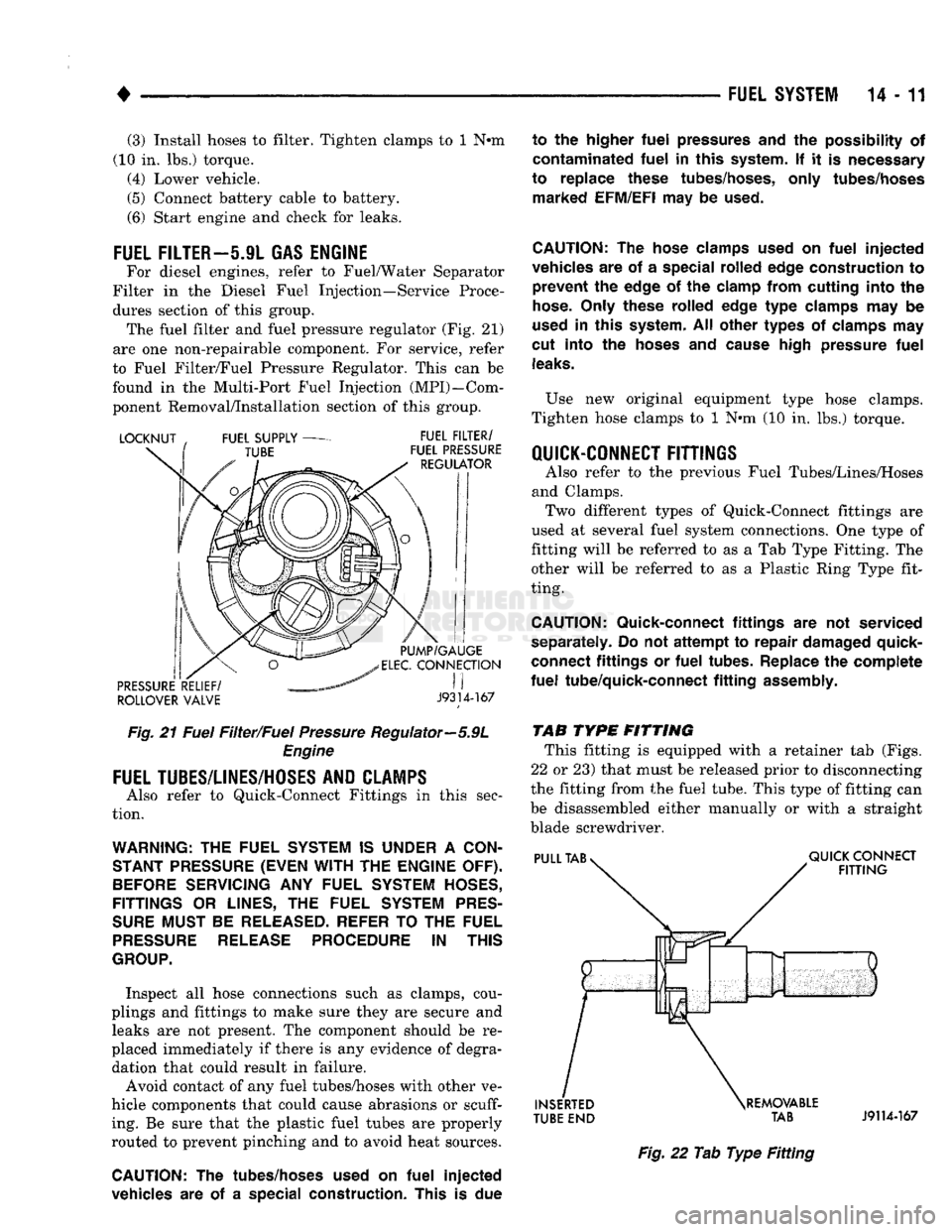
this group. The fuel filter
and
fuel pressure regulator
(Fig. 21)
are
one
non-repairable component.
For
service, refer
to Fuel Filter/Fuel Pressure Regulator. This
can be
found
in the
Multi-Port Fuel Injection (MPI)—Com
ponent Removal/Installation section
of
this group.
ROLLOVER VALVE
J9314-167
Fig.
21
Fuel Filter/Fuel Pressure Regulator—5.9L Engine
FUEL
TUBES/LINES/HOSES
AND CLAMPS
Also refer
to
Quick-Connect Fittings
in
this sec
tion.
WARNING:
THE
FUEL
SYSTEM
IS
UNDER
A
CON
STANT
PRESSURE
(EVEN WITH
THE
ENGINE
OFF).
BEFORE
SERVICING
ANY
FUEL
SYSTEM
HOSES,
FITTINGS
OR
LINES,
THE
FUEL
SYSTEM
PRES
SURE
MUST
BE
RELEASED-
REFER
TO
THE
FUEL
PRESSURE
RELEASE
PROCEDURE
IN
THIS
GROUP.
Inspect
all
hose connections such
as
clamps, cou
plings
and
fittings
to
make sure they
are
secure
and
leaks
are not
present.
The
component should
be re
placed immediately
if
there
is any
evidence
of
degra dation that could result
in
failure.
Avoid contact
of any
fuel tubes/hoses with other
ve
hicle components that could cause abrasions
or scuff
ing.
Be
sure that
the
plastic fuel tubes
are
properly
routed
to
prevent pinching
and to
avoid heat sources.
CAUTION:
The
tubes/hoses used
on
fuel
injected
vehicles
are of a
special construction. This
is due
to
the
higher
fuel
pressures
and the
possibility
of
contaminated
fuel
in
this system.
If it is
necessary
to replace these tubes/hoses, only tubes/hoses marked EFM/EFI
may
be
used.
CAUTION:
The
hose clamps used
on
fuel
injected
vehicles
are of a
special rolled edge construction
to
prevent
the
edge
of the
clamp from cutting into
the
hose.
Only these rolled edge
type
clamps
may be
used
in
this system.
All
other types
of
clamps
may
cut into
the
hoses
and
cause high pressure
fuel
leaks.
Use
new
original equipment type hose clamps.
Tighten hose clamps
to 1 N*m (10 in. lbs.)
torque.
QUICK-CONNECT FITTINGS
Also refer
to the
previous Fuel Tubes/Lines/Hoses
and Clamps. Two different types
of
Quick-Connect fittings
are
used
at
several fuel system connections.
One
type
of
fitting will
be
referred
to as a Tab
Type Fitting.
The
other will
be
referred
to as a
Plastic Ring Type fit
ting.
CAUTION:
Quick-connect fittings
are not
serviced
separately.
Do not
attempt
to
repair damaged quick-
connect fittings
or
fuel
tubes. Replace
the
complete
fuel
tube/quick-connect
fitting
assembly.
TAB
TYPE
FITTING This fitting
is
equipped with
a
retainer
tab
(Figs.
22
or
23) that must
be
released prior
to
disconnecting
the fitting from
the
fuel tube. This type
of
fitting
can
be disassembled either manually
or
with
a
straight
blade screwdriver.
TUBE
END TAB
J9114-167
Fig.
22 Tab
Type
Fitting
Page 834 of 1502
FUEL
DELIVERY—DIESEL
ENGINE
INDEX
page
Fuel Gauge Sending Unit Module
15
General Information
15
Manual
Shut Down Lever
. . 17
page
Mechanical
Lift
Pump
15
Quick
Connect Fittings—Except
Chassis
Fuel Tubes
17
GENERAL
INFORMATION
The fuel system of the 5.9L turbo-diesel engine
consists of the:
• Fuel tank • Low and high pressure fuel supply lines
• Mechanical lift pump
• Fuel/water separator filter
• Fuel heater
• Fuel injection pump • Fuel injectors
• Fuel return lines For information regarding fuel requirements of the
5.9L turbo diesel engine, refer to the Fuel Require
ments—Diesel Engines paragraph at the front of this group.
MECHANICAL
LIFT
PUMP
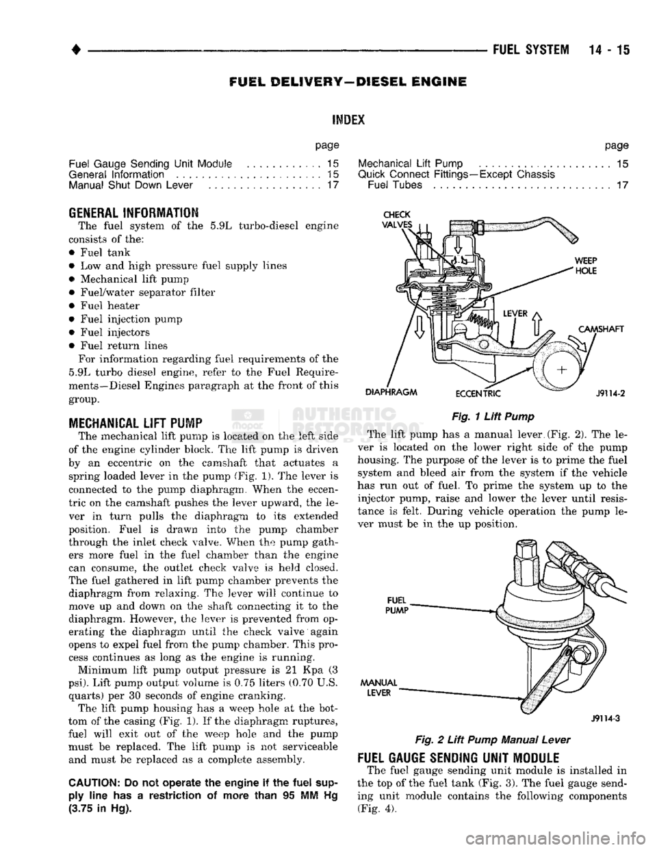
The mechanical lift pump is located on the left side
of the engine cylinder block. The lift pump is driven
by an eccentric on the camshaft that actuates a spring loaded lever in the pump (Fig. 1). The lever is
connected to the pump diaphragm. When the eccen
tric on the camshaft pushes the lever upward, the le ver in turn pulls the diaphragm to its extended
position. Fuel is drawn into the pump chamber
through the inlet check valve. When the pump gath ers more fuel in the fuel chamber than the engine
can consume, the outlet check valve is held closed.
The fuel gathered in lift pump chamber prevents the diaphragm from relaxing. The lever will continue to
move up and down on the shaft connecting it to the
diaphragm. However, the lever is prevented from op
erating the diaphragm until the check valve again
opens to expel fuel from the pump chamber. This pro cess continues as long as the engine is running.
Minimum lift pump output pressure is 21 Kpa (3
psi).
Lift pump output volume is 0.75 liters (0.70 U.S. quarts) per 30 seconds of engine cranking. The lift pump housing has a weep hole at the bot
tom of the casing (Fig. 1). If the diaphragm ruptures,
fuel will exit out of the weep hole and the pump
must be replaced. The lift pump is not serviceable and must be replaced as a complete assembly.
CAUTION:
Do not
operate
the
engine
if the
fuel
supply
line
has a
restriction
of
more than
95 MM Hg
(3.75
in Hg).
Fig.
1
Lift
Pump
The lift pump has a manual lever.(Fig. 2). The le
ver is located on the lower right side of the pump
housing. The purpose of the lever is to prime the fuel system and bleed air from the system if the vehicle
has run out of fuel. To prime the system up to the injector pump, raise and lower the lever until resis
tance is felt. During vehicle operation the pump le
ver must be in the up position.
J9114-3
Fig.
2
Lift
Pump
Manual
Lever
FUEL GAUGE SENDING
UNIT
MODULE
The fuel gauge sending unit module is installed in
the top of the fuel tank (Fig. 3). The fuel gauge send ing unit module contains the following components (Fig. 4).
Page 859 of 1502
14
- 40
FUEL
SYSTEM
• • Park/Neutral switch (gear indicator signal—auto,
trans,
only)
• Oxygen (02) sensor(s) Based on these inputs, the following occurs:
• Voltage is applied to the fuel injectors with the
PCM. The PCM will then adjust the injector pulse
width by turning the ground circuit to each individ
ual injector on and off.
• The PCM monitors the 02 sensor(s) input and ad
justs air-fuel ratio. It also adjusts engine idle speed through the idle air control (IAC) motor.
• The PCM adjusts ignition timing by turning the
ground path to the coil on and off.
• The PCM operates the A/C compressor clutch
through the clutch relay. This happens if A/C has
been selected by the vehicle operator and requested
by the A/C thermostat.
ACCELERATION MODE
This is an Open Loop mode. The powertrain control
module (PCM) recognizes an abrupt increase in
throttle position or MAP pressure as a demand for
increased engine output and vehicle acceleration.
The PCM increases injector pulse width in response
to increased throttle opening.
DECELERATION MODE
When the engine is at operating temperature, this
is an Open Loop mode. During hard deceleration, the
powertrain control module (PCM) receives the follow ing inputs.
• Air conditioning select signal (if equipped)
• Air conditioning request signal (if equipped)
• Battery voltage
• Engine coolant temperature sensor
• Crankshaft position sensor
• Intake manifold charge air temperature sensor
• Manifold absolute pressure (MAP) sensor
• Throttle position sensor (TPS)
• Camshaft position sensor signal (in the distributor)
• Park/Neutral switch (gear indicator signal —auto,
trans,
only)
If the vehicle is under hard deceleration with the
proper rpm and closed throttle conditions, the PCM
will ignore the oxygen sensor input signal. The PCM
will enter a fuel cut-off strategy in which it will not supply battery voltage to the injectors. If a hard de
celeration does not exist, the PCM will determine the
proper injector pulse width and continue injection.
Based on the above inputs, the PCM will adjust en
gine idle speed through the idle air control (IAC) mo
tor. The PCM adjusts ignition timing by turning the
ground path to the coil on and off.
The PCM opens the ground circuit to the A/C
clutch relay to disengage the A/C compressor clutch.
This is done until the vehicle is no longer under de
celeration (if the A/C system is operating).
WIDE OPEN
THROTTLE
MODE
This is an Open Loop mode. During wide open
throttle operation, the powertrain control module (PCM) receives the following inputs.
• Battery voltage
• Crankshaft position sensor
• Engine coolant temperature sensor
• Intake manifold charge air temperature sensor
• Manifold absolute pressure (MAP) sensor
• Throttle position sensor (TPS) • Camshaft position sensor signal (in the distributor) During wide open throttle conditions, the following
occurs:
• Voltage is applied to the fuel injectors with the
powertrain control module (PCM). The PCM will
then control the injection sequence and injector pulse
width by turning the ground circuit to each individ ual injector on and off. The PCM ignores the oxygen sensor input signal and provides a predetermined amount of additional fuel. This is done by adjusting
injector pulse width.
• The PCM adjusts ignition timing by turning the
ground path to the coil on and off.
• The PCM opens the ground circuit to the A/C
clutch relay to disengage the A/C compressor clutch.
This will be done for approximately 15 seconds (if the air conditioning system is operating).
If the vehicle has a manual transmission, the up
shift light is operated by the PCM.
IGNITION
SWITCH
OFF
MODE
When ignition switch is turned to OFF position,
the PCM stops operating the injectors, ignition coil,
ASD relay and fuel pump relay.
THROTTLE
BODY
Filtered air from the air cleaner enters the intake
manifold through the throttle body (Fig. 18). Fuel does not enter the intake manifold through the throt
tle body. Fuel is sprayed into the manifold by the fuel injectors. The throttle body is mounted on the
intake manifold. It contains an air control passage (Fig. 19) controlled by an idle air control (IAC) mo
tor. The air control passage is used to supply air for idle conditions. A throttle valve (plate) is used to supply air for above idle conditions. The throttle position sensor (TPS), idle air control
(IAC) motor and manifold absolute pressure sensor
(MAP) are attached to the throttle body. The acceler
ator pedal cable, speed control cable and transmis
sion control cable (when equipped) are connected to
the throttle arm. A (factory adjusted) set screw is used to mechani
cally limit the position of the throttle body throttle
plate. Never attempt to adjust the engine idle speed using this screw. All idle speed functions are
controlled by the PCM.