1993 DODGE TRUCK air filter
[x] Cancel search: air filterPage 922 of 1502
FUEL
SYSTEM
14-103
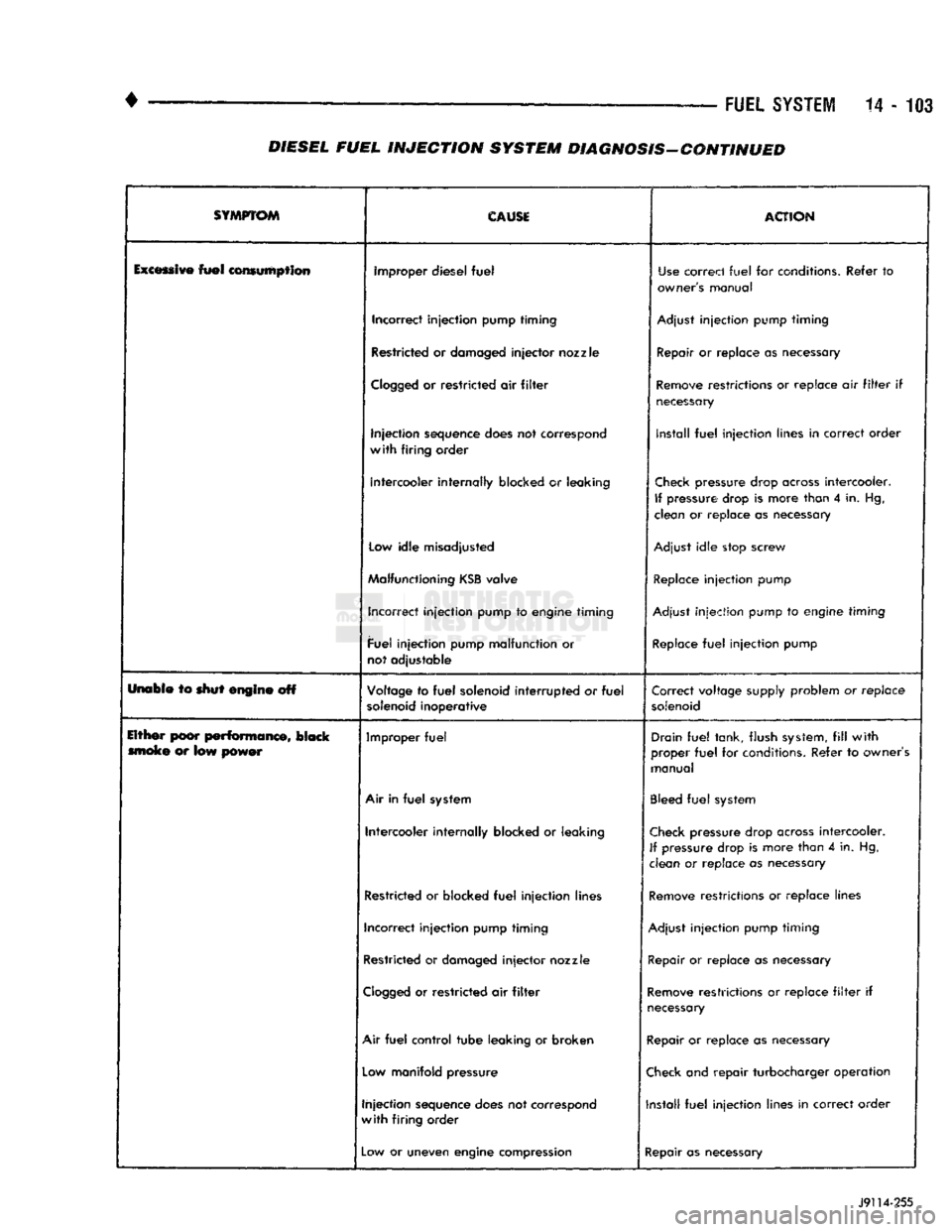
DIESEL FUEL
INJECTION
SYSTEM DIAGNOSIS-CONTINUED
SYMPTOM
CAUSE
ACTION
Excessive
fuel
consumption improper diesel
fuel
Use
correct
fuel
for conditions. Refer
to
owner's manual
Incorrect injection pump timing
Adjust
injection pump timing
Restricted or damaged
injector
nozzle Repair or replace as necessary
Clogged
or
restricted air
filter
Remove
restrictions or replace air
filter
if
necessary
Injection sequence does not correspond
with
firing order install
fuel
injection lines in correct order
Intercooler internally blocked
or
leaking
Check
pressure drop
across
intercooler.
If
pressure drop
is
more than
4
in. Hg,
clean or replace as necessary
Low
idle misadjusted
Adjust
idle stop screw
Malfunctioning
KSB
valve
Replace
injection pump
Incorrect injection pump to engine timing
Adjust
injection pump to engine timing
Fuel injection pump malfunction or
not adjustable
Replace
fuel
injection pump
Unabie to shut engine off Voltage to
fuel
solenoid
interrupted
or
fuel
solenoid
inoperative Correct voltage supply problem or
replace
solenoid
Either poor
performance,
black moke
or
low power Improper
fuel
Drain
fuel
tank, flush
system,
fill
with
proper
fuel
for conditions. Refer to owner's
manual
Air
in
fuel
system
Bleed
fuel
system
Intercooler internally blocked
or
leaking
Check
pressure drop
across
intercooler.
If
pressure drop is more than
4
in. Hg,
clean
or
replace
as
necessary
Restricted or blocked
fuel
injection lines
Remove
restrictions or replace lines
Incorrect injection pump timing
Adjust
injection pump timing
Restricted or damaged
injector
nozzle
Repair
or replace as necessary
Clogged
or restricted air
filter
Remove
restrictions or replace
filter
if
necessary
Air
fuel
control tube leaking or broken Repair or replace as necessary
Low
manifold pressure
Check
and repair turbocharger operation
Injection sequence does not correspond
with
firing order Install
fuel
injection lines in correct order
—
Low
or uneven engine compression
Repair as necessary
J9114-255
Page 923 of 1502
14-104
FUEL
SYSTEM
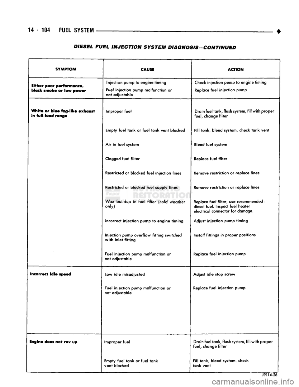
• DIESEL FUEL INJECTION SYSTEM DIAGNOSIS-CONTINUED
SYMPTOM
CAUSE
ACTION
Either poor performance,
black
smoke
or low
power
Injection
pump
to engine timing
Fuel injection pump malfunction or
not adjustable
Check
injection
pump
to
engine
timing
Replace
fuel
injection pump
White or blue fog-like exhaust in full-load range Improper
fuel
Drain
fuel
tank,
flush
system,
fill
with proper
fuel,
change
filter
Empty
fuel
tank or
fuel
tank vent blocked
Fill
tank, bleed
system,
check tank vent
Air
in
fuel
system
Bleed
fuel
system
Clogged
fuel
filter
Replace
fuel
filter
Restricted
or blocked
fuel
injection lines
Remove
restriction or replace lines
Restricted
or blocked
fuel
supply lines
Remove
restriction or replace lines
Wax
buildup in
fuel
filter
(cold weather
only)
Replace
fuel
filter,
use
recommended
i
diesel fuel.
Inspect
fuel
heater electrical connector for
damage.
Incorrect injection pump to engine timing
Adjust
injection pump timing
Injection pump overflow fitting switched
with inlet fitting Install fittings in
proper
positions
Fuel injection pump malfunction or
not adjustable
Replace
fuel
injection pump
Incorrect lale speed
Low
idle misadjusted
Adjust
idle
stop
screw
Fuel injection pump malfunction or
not adjustable
Replace
fuel
injection pump
Engine
does
not rev up Improper
fuel
Drain
fuel
tank,
flush
system,
fill
with proper
fuel,
change
filter
Empty
fuel
tank or
fuel
tank
vent blocked
Fill
tank, bleed
system,
check
tank vent J9114-26
Page 924 of 1502
•
FUEL
SYSTEM
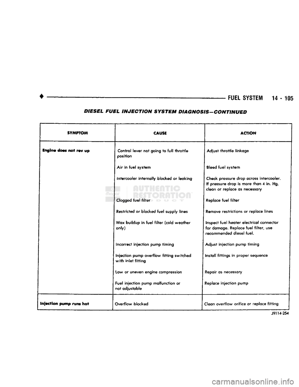
14-105 DIESEL FUEL INJECTION SYSTEM DIAGNOSIS-CONTINUED
SYMPTOM
CAUSE
ACTION
Engine
does not rev up Control lever not
going
to
full
throttle
position
Adjust
throttle
linkage
Air
in
fuel
system
Bleed
fuel
system
Intercooler internally blocked or leaking
Check
pressure drop
across
intercooler.
If pressure drop is more than 4 in. Hg,
clean or replace as necessary
Clogged
fuel
filter
Replace
fuel
filter
Restricted or blocked
fuel
supply lines
Remove
restrictions or replace lines
Wax
buildup in
fuel
filter
(cold weather only)
Inspect
fuel
heater
electrical
connector
for
damage.
Replace
fuel
filter,
use recommended diesel fuel.
Incorrect injection pump timing
Adjust
injection pump timing
Injection pump overflow
fitting
switched
with
inlet
fitting
Install fittings in proper sequence
Low
or uneven engine
compression
Repair
as
necessary
Fuel injection pump malfunction or
not adjustable
Replace
injection pump
Infection pump runs hot Overflow blocked
Clean
overflow orifice or replace
fitting
J9114-254
Page 925 of 1502
14
- 106
FUEL SYSTEi
DIESEL FUEL
INJECTION-SERVICE
PROCEDURES
INDEX
page
Air Bleed Procedure
106
Air Fuel Control Tube
107
Air Intake Heater
107
Engine
Speed
Sensor
108
Fuel Drain Manifold
109
Fuel Heater
. 110
Fuel
Injection
Pump
110
Fuel
Injection
Pump Supply Line
114
Fuel
Injectors
114
AIR BLEED PROCEDURE
A certain amount
of air
becomes trapped
in the
fuel system when fuel system components
are
ser
viced
or
replaced. Bleed
the
system after fuel system service according
to the
following procedures.
WARNING:
DO NOT
BLEED
AIR
FROM
THE
FUEL
SYSTEM
OF
A
HOT
ENGINE.
DO
NOT
ALLOW FUEL
TO SPRAY ONTO
THE
EXHAUST MANIFOLD WHEN BLEEDING
AIR
FROM
THE
FUEL SYSTEM.
MANUAL BLEEDING
Some
air
enters
the
fuel system when
the
filters
or
injection pump supply line
are
changed. This small
amount
of air is
vented automatically from
the
injec
tion pump through
the
fuel drain manifold. This
is if
the filter
was
changed according
to
instructions.
The system will have
to be
bleed manually
if:
•
The
fuel filter
is not
filled before installation
•
Injection pump
is
replaced
•
High pressure fuel line connections
are
loosened
or
lines replaced
•
Initial engine start-up
or
start-up after
an ex
tended period
of no
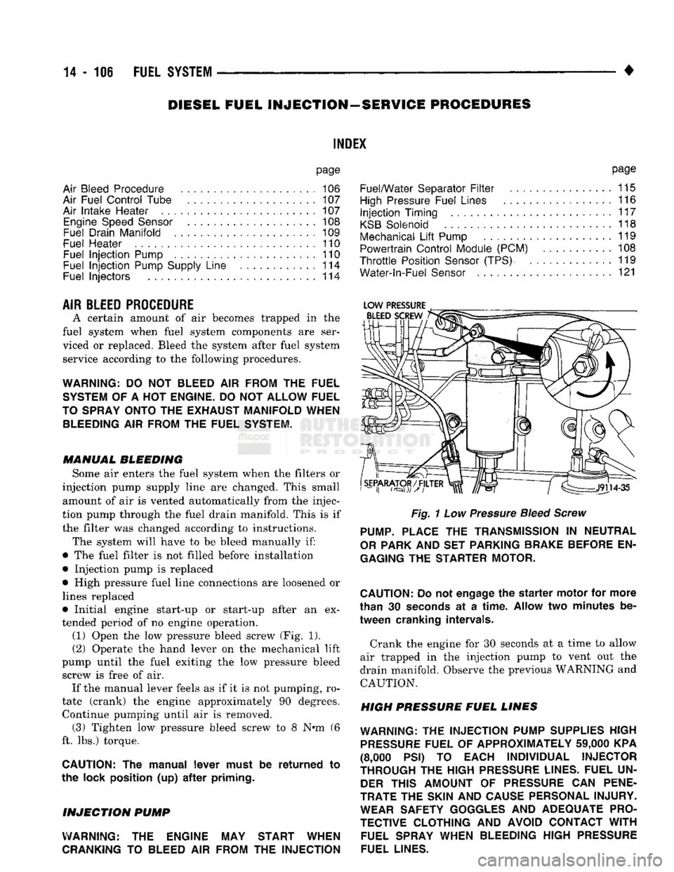
engine operation. (1) Open
the low
pressure bleed screw
(Fig. 1).
(2) Operate
the
hand lever
on the
mechanical lift
pump until
the
fuel exiting
the low
pressure bleed screw
is
free
of air.
If
the
manual lever feels
as if it is not
pumping,
ro
tate (crank)
the
engine approximately
90
degrees. Continue pumping until
air is
removed. (3) Tighten
low
pressure bleed screw
to 8 N»m (6
ft.
lbs.)
torque.
CAUTION:
The
manual lever must
be
returned
to
the lock position
(up) after
priming.
INJECTION
PUMP
WARNING:
THE
ENGINE
MAY
START WHEN
CRANKING
TO
BLEED
AIR
FROM
THE
INJECTION
page
Fuel/Water Separator
Filter
................
115
High
Pressure Fuel Lines
116
Injection
Timing
117
KSB
Solenoid
118
Mechanical
Lift
Pump
119
Powertrain Control Module (PCM)
108
Throttle
Position
Sensor
(TPS)
119
Water-ln-Fuel
Sensor
121
Fig.
1
Low
Pressure
Bleed Screw
PUMP.
PLACE
THE
TRANSMISSION
IN
NEUTRAL
OR
PARK
AND SET
PARKING BRAKE BEFORE
EN
GAGING
THE
STARTER MOTOR.
CAUTION:
Do
not
engage
the
starter
motor
for
more
than
30
seconds
at a
time.
Allow
two
minutes
be
tween cranking intervals.
Crank
the
engine
for 30
seconds
at a
time
to
allow
air trapped
in the
injection pump
to
vent
out the
drain manifold. Observe
the
previous WARNING
and
CAUTION.
HIGH PRESSURE FUEL LINES
WARNING:
THE
INJECTION PUMP SUPPLIES HIGH
PRESSURE
FUEL
OF
APPROXIMATELY
59,000
KPA
(8,000
PSI) TO
EACH INDIVIDUAL INJECTOR
THROUGH
THE
HIGH
PRESSURE
LINES. FUEL
UN
DER
THIS AMOUNT
OF
PRESSURE
CAN
PENE
TRATE
THE
SKIN
AND
CAUSE PERSONAL INJURY. WEAR SAFETY GOGGLES
AND
ADEQUATE PRO
TECTIVE CLOTHING
AND
AVOID CONTACT
WITH
FUEL SPRAY WHEN BLEEDING HIGH
PRESSURE
FUEL LINES.
Page 933 of 1502
14 - 114
FUEL
SYSTEM
• (15) Install fuel injection pump supply line. Refer
to Fuel Injection Pump Supply Line.
(16) Connect electrical connector to fuel solenoid.
(17) Connect electrical connector to KSB solenoid.
(18) Install fuel pump vent line and capscrew.
(19) Install air fuel control tube.
(20) Install throttle bracket (Fig. 15). Tighten
mounting bolts to 24 N»m (18 ft. lbs.) torque.
(21) Install throttle linkage. When connecting the
cable to the control lever, adjust the length so the le
ver has stop-to-stop movement. Refer to Accelerator
Pedal and Throttle Controls section of Group 14,
Fuel Systems.
(22) Install and adjust throttle position sensor. Re
fer to Service Adjustments.
(23) Bleed air from fuel system. Refer to High
Pressure Fuel Lines in the Air Bleeding portion of
the Diesel Fuel Injection section of Group 14, Fuel Systems. (24) Adjust the low idle speed if required. Refer to
Service Adjustments near the end of this group. (25) Inspect throttle linkage to be sure that the
control lever breaks over the full throttle position.
Adjust as necessary. Refer to Accelerator Pedal and
Throttle Cable section of Group 14, Fuel Systems.
FUEL
INJECTION
PUMP
SUPPLY
LINE
REMOVAL
(1) Disconnect negative cable from battery.
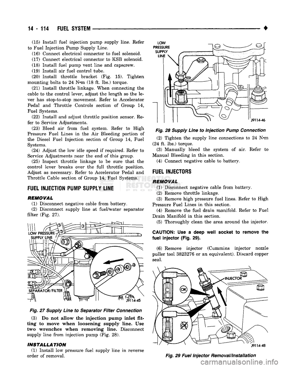
(2) Disconnect supply line at fuel/water separator
filter (Fig. 27).
Fig.
27
Supply
Line
to Separator
Filter
Connection
(3) Do not allow the injection pump inlet fit
ting to move when loosening supply line. Use two wrenches when removing line. Disconnect
supply line from injection pump (Fig. 28).
INSTALLATION
(1) Install low pressure fuel supply line in reverse
order of removal.
Fig.
28
Supply
Line
to Injection
Pump
Connection
(2) Tighten the supply line connections to 24 Nnn
(24 ft. lbs.) torque.
(3) Manually bleed the system of air. Refer to
Manual Bleeding in this section.
(4) Connect negative cable to battery.
FUEL
INJECTORS
REMOVAL
(1) Disconnect negative cable from battery.
(2) Remove throttle linkage.
(3) Remove high pressure fuel lines. Refer to High
Pressure Fuel Lines in this section. (4) Remove the fuel drain manifold. Refer to Fuel
Drain Manifold in this section. (5) Thoroughly clean the area around the injector.
CAUTION:
Use a deep
well
socket
to remove the
fuel
injector (Fig. 29).
(6) Remove injector (Cummins injector nozzle
puller tool 3823276 or an equivalent). Discard copper seal.
Fig.
29
Fuel
Injector Removal/Installation
Page 934 of 1502
FUEL SYSTEM
14 - 115
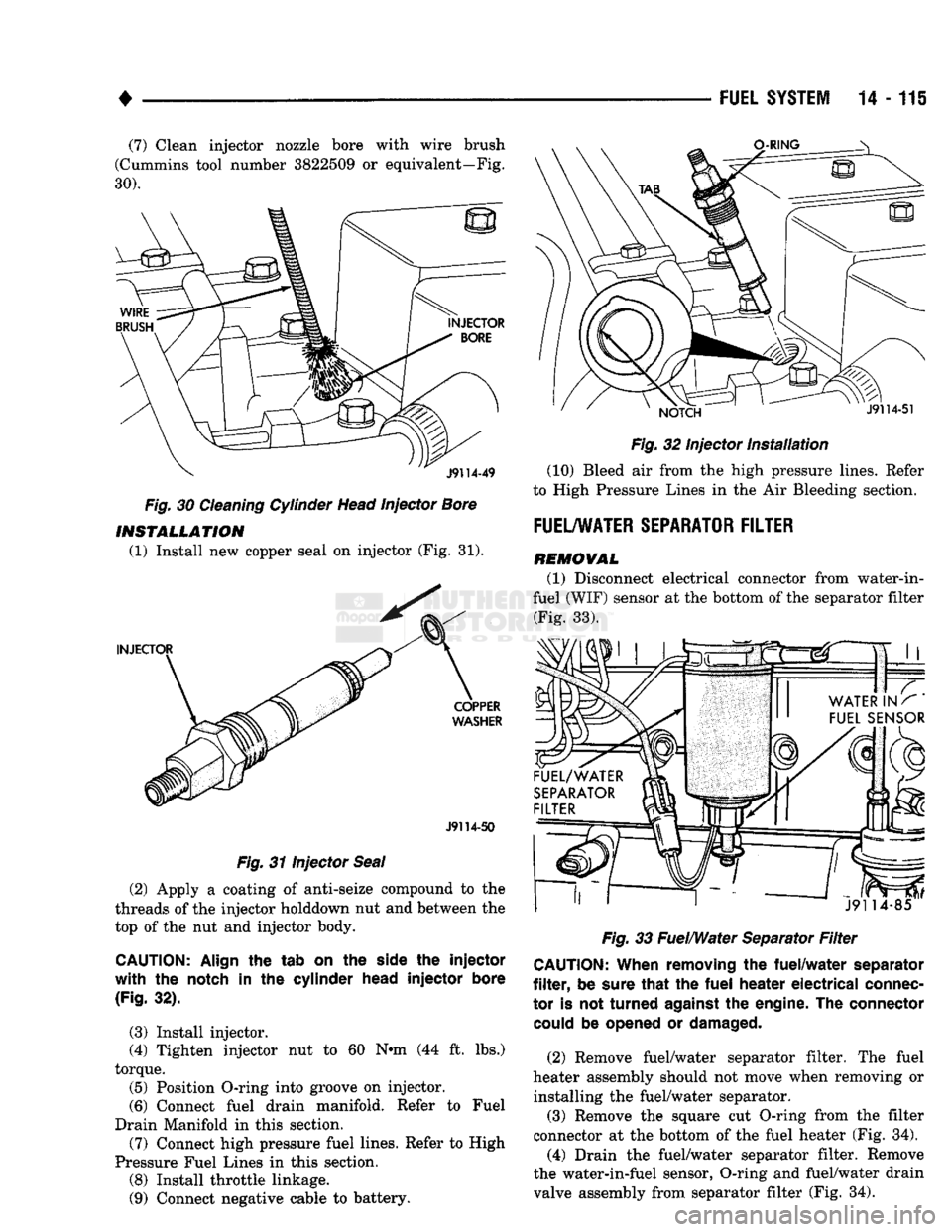
(7) Clean injector nozzle bore with wire brush
(Cummins tool number 3822509
or
equivalent—Fig.
30).
Fig.
30
Cleaning Cylinder Head Injector Bore INSTALLATION
(1) Install
new
copper seal
on
injector
(Fig. 31).
J9114-50
Fig.
31
Injector Seal
(2) Apply
a
coating
of
anti-seize compound
to the
threads
of the
injector holddown
nut and
between
the
top
of the nut and
injector body.
CAUTION:
Align
the tab on the
side
the injector
with the
notch
in the
cylinder
head
injector
bore
(Fig.
32).
(3) Install injector.
(4) Tighten injector
nut to 60 N«m (44 ft. lbs.)
torque. (5) Position O-ring into groove
on
injector.
(6) Connect fuel drain manifold. Refer
to
Fuel
Drain Manifold
in
this section.
(7) Connect high pressure fuel lines. Refer
to
High
Pressure Fuel Lines
in
this section.
(8) Install throttle linkage.
(9) Connect negative cable
to
battery.
Fig.
32
Injector
Installation
(10) Bleed
air
from
the
high pressure lines. Refer
to High Pressure Lines
in the Air
Bleeding section.
FUEL/WATER SEPARATOR FILTER
REMOVAL
(1) Disconnect electrical connector from water-in-
fuel (WIF) sensor
at the
bottom
of
the separator filter (Fig.
33).
Fig.
33
Fuel/Water Separator
Filter
CAUTION:
When
removing
the
fuel/water
separator
filter,
be
sure
that
the fuel
heater
electrical
connec
tor
is not
turned
against
the
engine.
The connector
could
be
opened
or
damaged.
(2) Remove fuel/water separator filter.
The
fuel
heater assembly should
not
move when removing
or
installing
the
fuel/water separator. (3) Remove
the
square
cut
O-ring from
the
filter
connector
at the
bottom
of the
fuel heater
(Fig. 34).
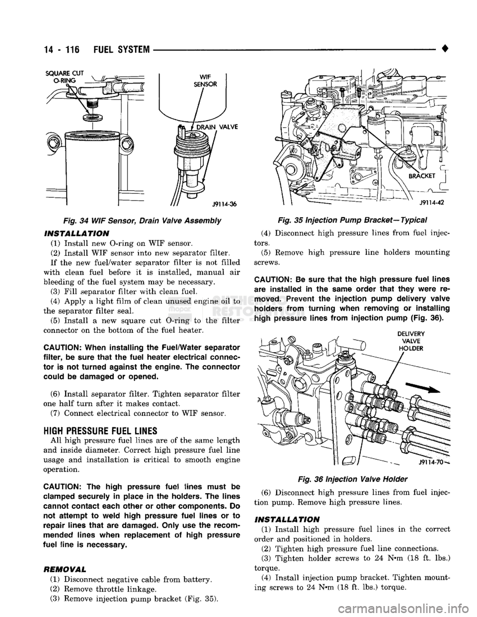
(4) Drain
the
fuel/water separator filter. Remove
the water-in-fuel sensor, O-ring
and
fuel/water drain
valve assembly from separator filter
(Fig. 34).
Page 935 of 1502
14
• 116
FUEL
SYSTEM
Fig.
34 WIF
Sensor,
Drain
Valve
Assembly
INSTALLATION
(1) Install new O-ring on WIF sensor.
(2) Install WIF sensor into new separator filter.
If the new fuel/water separator filter is not filled
with clean fuel before it is installed, manual air
bleeding of the fuel system may be necessary. (3) Fill separator filter with clean fuel.
(4) Apply a light film of clean unused engine oil to
the separator filter seal.
(5) Install a new square cut O-ring to the filter
connector on the bottom of the fuel heater.
CAUTION:
When installing
the
Fuel/Water separator
filter,
be
sure
that
the
fuel
heater
electrical
connec
tor
is not
turned
against
the
engine.
The
connector could
be
damaged
or
opened.
(6) Install separator filter. Tighten separator filter
one half turn after it makes contact.
(7) Connect electrical connector to WIF sensor.
HIGH
PRESSURE
FUEL LINES
All high pressure fuel lines are of the same length
and inside diameter. Correct high pressure fuel line
usage and installation is critical to smooth engine
operation.
CAUTION:
The
high pressure
fuel
lines must
be
clamped securely
in
place
in the
holders.
The
lines
cannot contact each other
or
other components.
Do
not
attempt
to
weld high pressure
fuel
lines
or to
repair lines
that
are
damaged. Only
use the
recom
mended lines when replacement
of
high pressure
fuel
line
is
necessary.
REMOVAL
(1) Disconnect negative cable from battery.
(2) Remove throttle linkage.
(3) Remove injection pump bracket (Fig. 35).
Fig.
35 Injection
Pump
Bracket—
Typical
(4) Disconnect high pressure lines from fuel injec
tors.
(5) Remove high pressure line holders mounting
screws.
CAUTION:
Be
sure
that
the
high pressure
fuel
lines
are installed
in the
same order
that
they
were
re
moved.
Prevent
the
injection
pump delivery valve
holders from turning when removing
or
installing
high
pressure lines from
injection
pump (Fig.
36).
Fig.
36 Injection
Valve
Holder
(6) Disconnect high pressure lines from fuel injec
tion pump. Remove high pressure lines.
INSTALLATION
(1) Install high pressure fuel lines in the correct
order and positioned in holders.
(2) Tighten high pressure fuel line connections.
(3) Tighten holder screws to 24 N-m (18 ft. lbs.)
torque.
(4) Install injection pump bracket. Tighten mount
ing screws to 24 N*m (18 ft. lbs.) torque.
Page 941 of 1502
14
- 122
FUEL
SYSTEM
• (6) Install separator filter. Tighten separator filter
one half turn after it makes contact.
(7) Connect electrical connector to WIF sensor and
fuel heater.
GENERAL
INFORMATION
The low idle speed adjustment is the only adjust
ment that can be made to the injection pump. The
fuel solenoid is the only component that can be ser viced on the injection pump. Refer to Service Procedures section for fuel solenoid service. All other
injection pump service must be performed by authorized personnel.
LOW IDLE
SPEED
Use an optical tachometer such as Snap-on No.
MT139 or MTE (Cummins tool division) No. 3377462
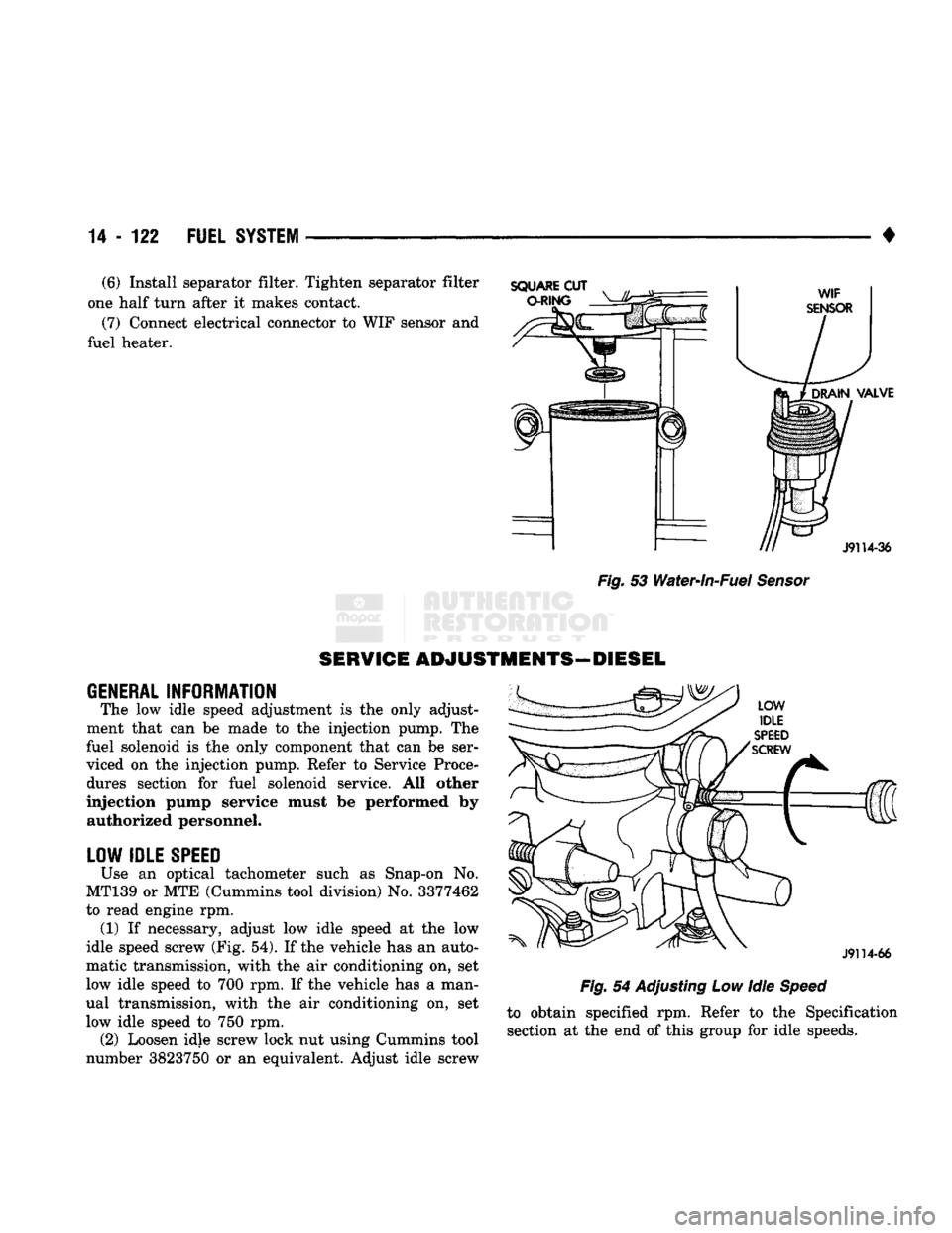
to read engine rpm. (1) If necessary, adjust low idle speed at the low
idle speed screw (Fig. 54). If the vehicle has an auto
matic transmission, with the air conditioning on, set
low idle speed to 700 rpm. If the vehicle has a man
ual transmission, with the air conditioning on, set
low idle speed to 750 rpm. (2) Loosen idle screw lock nut using Cummins tool
number 3823750 or an equivalent. Adjust idle screw
Fig.
54 Adjusting Low Idle
Speed
to obtain specified rpm. Refer to the Specification section at the end of this group for idle speeds.
SERVICE ADJUSTMENTS—DIESEL