1993 DODGE TRUCK air filter
[x] Cancel search: air filterPage 904 of 1502
•
FUEL SYSTEM
14-85 to pass through it, but prevents moisture (water)
from doing so. Moisture collects at the bottom of the
separator filter.
WARNING:
EXTINGUISH
ALL
SMOKING
MATERI
ALS
BEFORE
DRAINING
THE
FUEL/WATER
SEPA
RATOR
FILTER.
There is a drain at the bottom of the separator fil
ter (Fig. 16). Place a drain pan under the drain tube.
With the engine not running, push up on the drain
to remove the water from the separator filter. Hold
the drain open until all water and contaminants
have been removed and clean fuel exits the drain. Dispose of mixture in drain pan according to applica
ble regulations.
Refer to the maintenance schedules in Group 0 in
this manual for the recommended fuel/water separa
tor filter replacement intervals.
KSB
SOLENOID
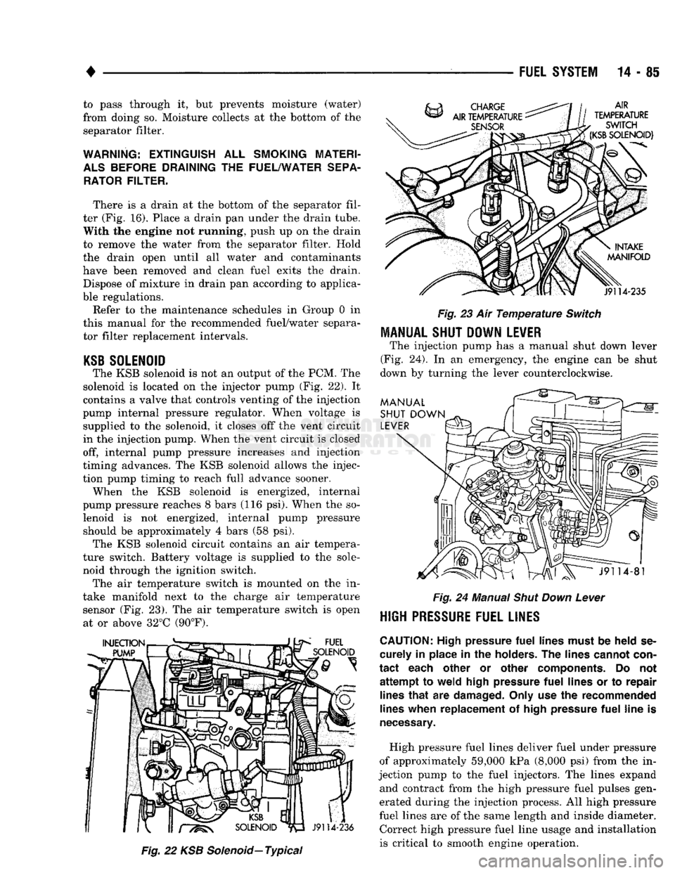
The KSB solenoid is not an output of the PCM. The
solenoid is located on the injector pump (Fig. 22). It
contains a valve that controls venting of the injection
pump internal pressure regulator. When voltage is supplied to the solenoid, it closes off the vent circuit
in the injection pump. When the vent circuit is closed
off, internal pump pressure increases and injection
timing advances. The KSB solenoid allows the injec
tion pump timing to reach full advance sooner. When the KSB solenoid is energized, internal
pump pressure reaches 8 bars (116 psi). When the so lenoid is not energized, internal pump pressure should be approximately 4 bars (58 psi). The KSB solenoid circuit contains an air tempera
ture switch. Battery voltage is supplied to the sole
noid through the ignition switch. The air temperature switch is mounted on the in
take manifold next to the charge air temperature sensor (Fig. 23). The air temperature switch is open at or above 32°C (90°F).
Fig.
22 KSB
Solenoid—
Typical
Fig.
23 Air
Temperature
Switch
MANUAL SHUT DOWN LEVER
The injection pump has a manual shut down lever
(Fig. 24). In an emergency, the engine can be shut
down by turning the lever counterclockwise.
Fig.
24 Manual
Shut
Down
Lever
HIGH
PRESSURE FUEL LINES
CAUTION:
High pressure
fuel
lines must
be
held
se
curely
in
place
in the
holders.
The
lines cannot con
tact
each other
or
other components.
Do not
attempt
to
weld high pressure
fuel
lines
or to
repair lines
that
are
damaged. Only use
the
recommended
lines when replacement
of
high pressure
fuel
line
is
necessary.
High pressure fuel lines deliver fuel under pressure
of approximately 59,000 kPa (8,000 psi) from the in
jection pump to the fuel injectors. The lines expand and contract from the high pressure fuel pulses gen
erated during the injection process. All high pressure
fuel lines are of the same length and inside diameter. Correct high pressure fuel line usage and installation
is critical to smooth engine operation.
Page 907 of 1502
DIESEL FUEL INJECTION—GENERAL DIAGNOSIS
INDEX
page
Air
in
Fuel System
90
Air Intake Heater
. 90
Diagnostic
Trouble Code (DTC)
. 95
DRB
II
Scan
Tool
95
Engine
Speed
Sensor
91
Fuel Heater
91
Fuel
Injection
Pump
91
Fuel Injectors
92
Fuel Supply Restrictions
92
page
Fuel/Water Separator
Filter 92
High
Pressure Fuel Line Restrictions
93
KSB
Solenoid
. 93
Mechanical
Lift
Pump
93
On-Board
Diagnostics (OBD)
94
System
Schematics—5.9L Diesel Engine
....... 95
Throttle
Position
Sensor
Test
94
Visual
Inspection
88
VISUAL
INSPECTION
A visual inspection for loose, disconnected, or incor
rectly routed wires and hoses should be made before attempting to diagnose or service the fuel injection
system. A visual check will help find these condi
tions.
It also saves unnecessary test and diagnostic
time.
A thorough visual inspection of the fuel injec
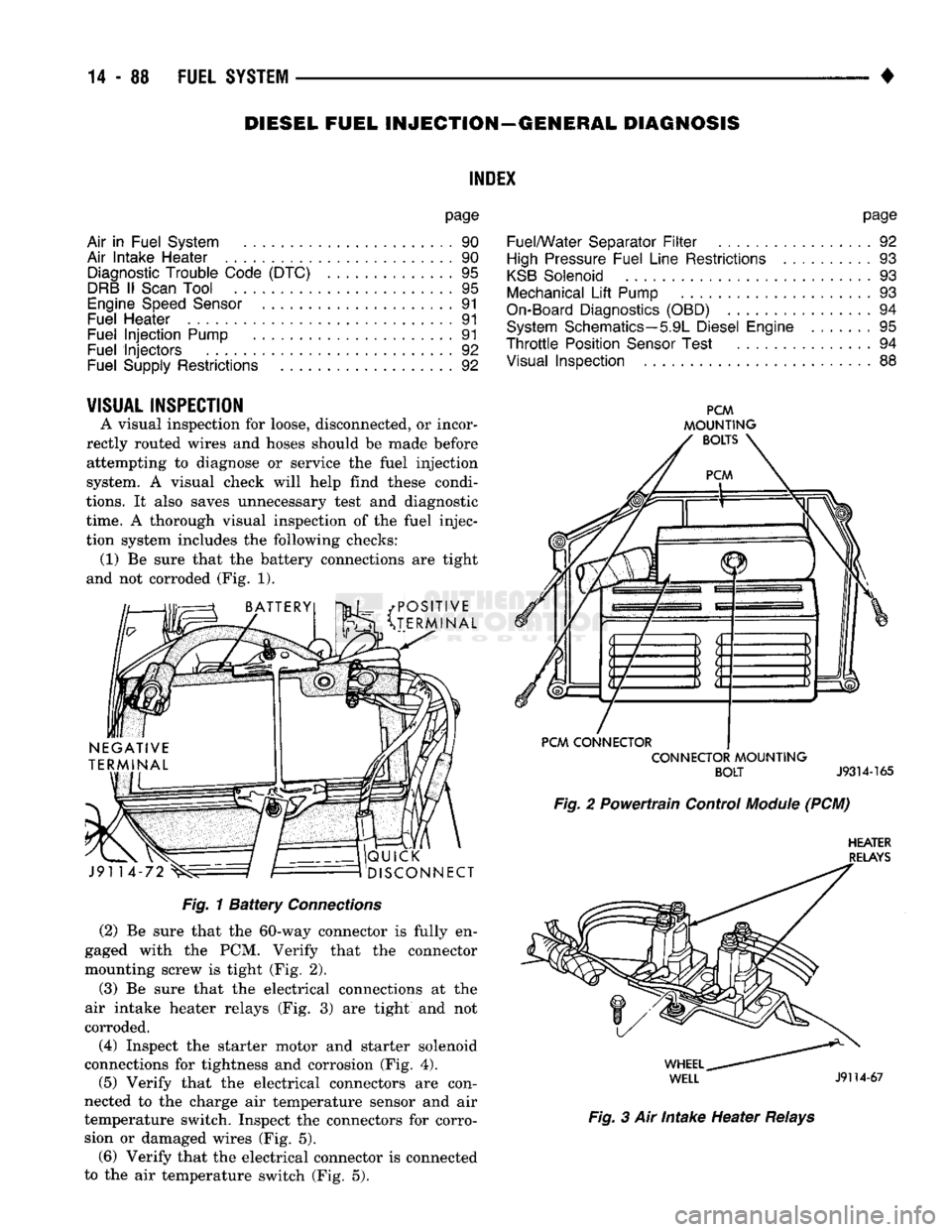
tion system includes the following checks: (1) Be sure that the battery connections are tight
and not corroded (Fig. 1).
• POSITIVE
v^3t
^TERMINAL J91 14
QUICK
DISCONNECT
PCM
MOUNTING
BOLTS
PCM
CONNECTOR CONNECTOR
MOUNTING
BOLT
J9314-165
Fig.
2 Powertrain Control
Module
(PCM)
HEATER
RELAYS
Fig.
1
Battery
Connections
(2)
Be sure that the 60-way connector is fully en
gaged with the PCM. Verify that the connector
mounting screw is tight (Fig. 2).
(3)
Be sure that the electrical connections at the
air intake heater relays (Fig. 3) are tight and not
corroded.
(4)
Inspect the starter motor and starter solenoid
connections for tightness and corrosion (Fig. 4).
(5)
Verify that the electrical connectors are con
nected to the charge air temperature sensor and air
temperature switch. Inspect the connectors for corro sion or damaged wires (Fig. 5). (6) Verify that the electrical connector is connected
to the air temperature switch (Fig. 5).
WHEEL
^
WELL
J9114-67
Fig.
3 Air Intake Heater
Relays
Page 909 of 1502
14
- 90
FUEL SYSTEM
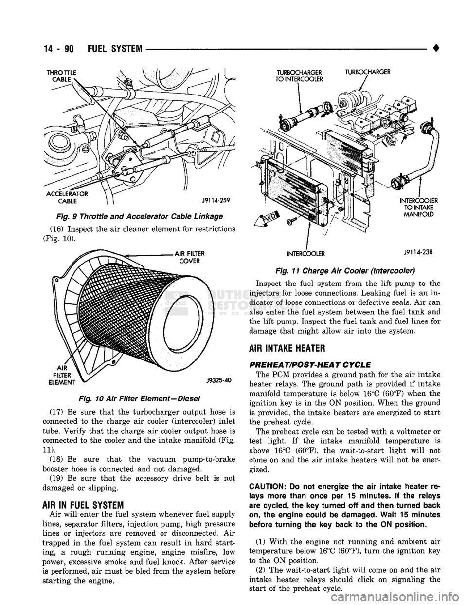
Fig.
10 Air
Filter
Element—Diesel (17) Be sure that the turbocharger output hose is
connected to the charge air cooler (intercooler) inlet
tube.
Verify that the charge air cooler output hose is
connected to the cooler and the intake manifold (Fig.
11).
(18) Be sure that the vacuum pump-to-brake
booster hose is connected and not damaged. (19) Be sure that the accessory drive belt is not
damaged or slipping.
AIR
IN
FUEL SYSTEM
Air will enter the fuel system whenever fuel supply
lines,
separator filters, injection pump, high pressure
lines or injectors are removed or disconnected. Air
trapped in the fuel system can result in hard start
ing, a rough running engine, engine misfire, low
power, excessive smoke and fuel knock. After service is performed, air must be bled from the system before
starting the engine. •
Fig.
11
Charge
Air
Cooler
(Intercooler) Inspect the fuel system from the lift pump to the
injectors for loose connections. Leaking fuel is an in
dicator of loose connections or defective seals. Air can also enter the fuel system between the fuel tank and
the lift pump. Inspect the fuel tank and fuel lines for damage that might allow air into the system.
AIR INTAKE HEATER PREHEAT/POST-HEAT CYCLE
The PCM provides a ground path for the air intake
heater relays. The ground path is provided if intake
manifold temperature is below 16°C (60°F) when the
ignition key is in the ON position. When the ground is provided, the intake heaters are energized to start
the preheat cycle.
The preheat cycle can be tested with a voltmeter or
test light. If the intake manifold temperature is above 16°C (60°F), the wait-to-start light will not
come on and the air intake heaters will not be ener gized.
CAUTION:
Do not
energize
the air
intake
heater
re
lays
more than once
per 15
minutes.
If the
relays
are cycled,
the key
turned
off and
then
turned
back
on,
the
engine could
be
damaged. Wait
15
minutes before turning
the key
back
to the ON
position.
(1) With the engine not running and ambient air
temperature below 16°C (60°F), turn the ignition key
to the ON position.
(2) The wait-to-start light will come on and the air
intake heater relays should click on signaling the
start of the preheat cycle.
Page 911 of 1502
14-92
FUEL
SYSTEM
• A broken injection pump timing mechanism spring
will cause the timing to be fully advanced resulting
in torque loss, a fuel knock and possible engine over
heating.
An improperly operating KSB (cold start) solenoid
will cause white smoke during engine warm-up. The
KSB solenoid is not serviceable.
A defective or non-adjustable fuel injection pump
can cause starting problems or prevent the engine
from revving up. It can also cause:
• Engine surge at idle • Rough idle (warm engine)
• Engine miss under load
• Low power
• Excessive fuel consumption
• Poor performance
• Low power
• Black smoke from the exhaust • Blue or white fog like exhaust
• Incorrect idle or maximum speed A worn fuel injection pump plunger can effect fuel
pressure and the amount of fuel injected. This results in reduced engine power. In most cases, if the injec
tion pump is delivering fuel from one outlet, it will deliver fuel from all outlets. If the internal plunger is defective, the fuel injection pump must be re
placed.
Engine power is also effected by the governor set
ting and performance. Do not attempt to adjust the governor. If the governor seals on the external adjustment screw are broken, the fuel rate may
be out of adjustment. The warranty of the injec tion pump and the engine may be void if the
seals have been tampered with or removed.
FUEL
INJECTORS
A leaking fuel injector can cause fuel knock, poor
performance, black smoke, poor fuel economy and
rough engine idle. If the fuel injector needle valve
does not operate properly, the engine may misfire and produce low power. A leak in the injection pump-to-injector high pres
sure fuel line can cause many of the same symptoms as a malfunctioning injector. Inspect for a leak in the
high pressure lines before checking for a malfunc
tioning fuel injector.
WARNING:
THE
INJECTION PUMP SUPPLIES HIGH
PRESSURE
FUEL
OF
APPROXIMATELY
59,000
KPA
(8,000
PSI) TO
EACH INDIVIDUAL INJECTOR
THROUGH THE HIGH
PRESSURE
LINES. FUEL UN
DER
THIS AMOUNT
OF
PRESSURE
CAN
PENE
TRATE THE SKIN AND CAUSE PERSONAL INJURY,
WEAR
SAFETY GOGGLES
AND
ADEQUATE PRO
TECTIVE CLOTHING. AVOID CONTACT
WITH
FUEL
SPRAY
WHEN BLEEDING HIGH
PRESSURE
FUEL
LINES.
WARNING:
DO NOT
BLEED
AIR
FROM
THE
FUEL
SYSTEM
OF A
HOT ENGINE.
DO
NOT ALLOW FUEL
TO SPRAY ONTO THE EXHAUST MANIFOLD WHEN
BLEEDING
AIR
FROM THE FUEL SYSTEM.
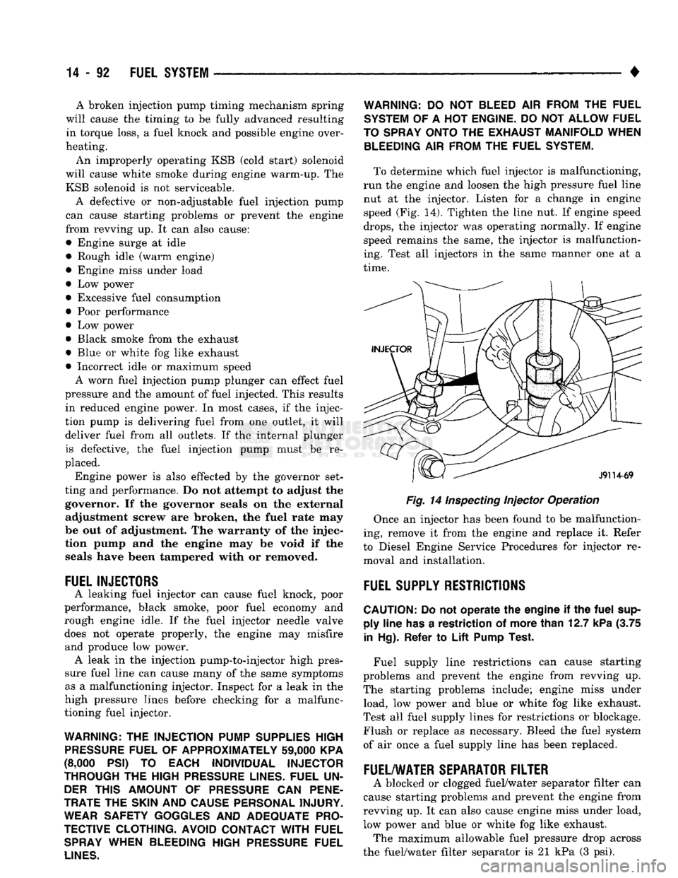
To determine which fuel injector is malfunctioning,
run the engine and loosen the high pressure fuel line nut at the injector. Listen for a change in engine
speed (Fig. 14). Tighten the line nut. If engine speed
drops,
the injector was operating normally. If engine
speed remains the same, the injector is malfunction
ing. Test all injectors in the same manner one at a
time.
Fig. 14
Inspecting
Injector Operation
Once an injector has been found to be malfunction
ing, remove it from the engine and replace it. Refer
to Diesel Engine Service Procedures for injector re moval and installation.
FUEL
SUPPLY
RESTRICTIONS
CAUTION:
Do not
operate
the
engine
if the
fuel
sup ply
line
has
a
restriction
of
more
than
12.7
kPa
(3.75
in
Hg).
Refer
to
Lift
Pump
Test.
Fuel supply line restrictions can cause starting
problems and prevent the engine from revving up.
The starting problems include; engine miss under load, low power and blue or white fog like exhaust.
Test all fuel supply lines for restrictions or blockage.
Flush or replace as necessary. Bleed the fuel system
of air once a fuel supply line has been replaced.
FUEL/WATER
SEPARATOR
FILTER
A blocked or clogged fuel/water separator filter can
cause starting problems and prevent the engine from
revving up. It can also cause engine miss under load,
low power and blue or white fog like exhaust. The maximum allowable fuel pressure drop across
the fuel/water filter separator is 21 kPa (3 psi).
Page 912 of 1502
•
FUEL SYSTEM
14-93 There is a drain at the bottom of the separator fil
ter (Fig. 13). Place a drain pan under the drain tube. With the engine not running, hold the drain open
until all water and contaminants have been removed and clean fuel exits the drain. Dispose of mixture in
drain pan according to applicable regulations.
If excess water gathers in separator/filter in a short
time,
the fuel tank must be removed, drained and cleaned.
HIGH
PRESSURE FUEL LINE RESTRICTIONS
High pressure fuel line leaks can cause starting
problems, poor engine performance and engine miss under load. Restricted high pressure lines can cause starting problems, poor engine performance, engine
miss under load and black smoke from exhaust.
WARNING:
USE
EXTREME
CAUTION
WHEN
IN
SPECTING
FOR HIGH
PRESSURE
FUEL
LEAKS.
IN
SPECT
FOR HIGH
PRESSURE
FUEL
LEAKS
WITH
A
SHEET
OF
CARDBOARD.
HIGH
FUEL
INJECTION
PRESSURE
CAN
CAUSE
PERSONAL
INJURY
IF
CONTACT
IS
MADE
WITH
THE
SKIN.
Start the engine. Move the cardboard over the high
pressure fuel lines and check for fuel spray onto the cardboard. If a high pressure line connection is leak
ing, bleed the system and tighten the connection. Re
fer to the 5.9L Diesel Service Procedures section for air bleeding procedures. Replace damaged, restricted
or leaking high pressure fuel lines with the correct replacement line.
CAUTION:
The
high pressure
fuel
lines must
be
clamped securely
in
place
in the
holders.
The
lines cannot contact each other
or
other components.
Do
not
attempt
to
weld high pressure
fuel
lines
or to
repair lines
that
are
damaged. Only
use the
recom
mended lines when replacement
of
high pressure
fuel
line
is
necessary.
KSB
SOLENOID
The KSB solenoid will click when it is energized
and de-energized. If the solenoid does not click when 12 volts is sup
plied to it, replace the solenoid.
MECHANICAL
LIFT
PUMP
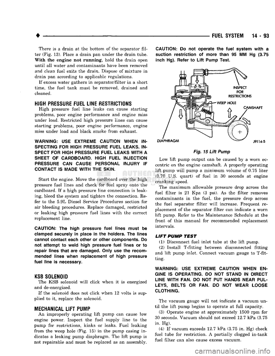
An improperly operating lift pump can cause low
engine power. Inspect the fuel supply line to the
pump for restrictions, kinks or leaks. Fuel leaking
from the weep hole (Fig. 15) in the pump casing in
dicates a leaking pump diaphragm. The lift pump is not repairable and must be replaced as an assembly.
CAUTION:
Do not
operate
the
fuel
system
with
a
suction restriction
of
more than
95 MM Hg (3.75
inch Hg). Refer
to
Lift
Pump Test.
Fig.
15
Lift
Pump
Low lift pump output can be caused by a worn ec
centric on the engine camshaft. A properly operating lift pump will pump a minimum volume of 0.75 liter (0.70 U.S. quart) of fuel in 30 seconds at engine
cranking speed.
The maximum allowable pressure drop across the
fuel filter is 21 Kpa (3 psi). As the filter removes contaminants in the fuel, the pressure drop across
the fuel separator filter will increase. Frequent re
placement of the separator filter can indicate a worn lift pump. Refer to the Maintenance Schedule at the
front of this manual for recommended replacement intervals.
LIFT
PUMP
TEST
(1) Disconnect fuel inlet tube at the lift pump. (2) Install T-fitting between disconnected fitting
and lift pump inlet. Connect vacuum gauge to T-fit
ting.
WARNING:
USE
EXTREME
CAUTION
WHEN
EN
GINE
IS
OPERATING.
DO NOT
STAND
IN
DIRECT
LINE
WITH FAN.
DO NOT PUT
HANDS
NEAR
PUL
LEYS,
BELTS
OR FAN. DO NOT
WEAR
LOOSE
CLOTHING.
The vacuum gauge will not indicate a vacuum un
til the lift pump begins to operate at full capacity.
(3) Operate engine at approximately 1500 rpm for
30 seconds. Vacuum should not exceed 12.7 kPa (3.75
in. Hg).
(4) If vacuum exceeds 12.7 kPa (3.75 in. Hg) check
fuel tube for restriction. A partially clogged in-tank fuel filter can also cause excess vacuum.
Page 919 of 1502
14-100
FUEL
SYSTEM
•
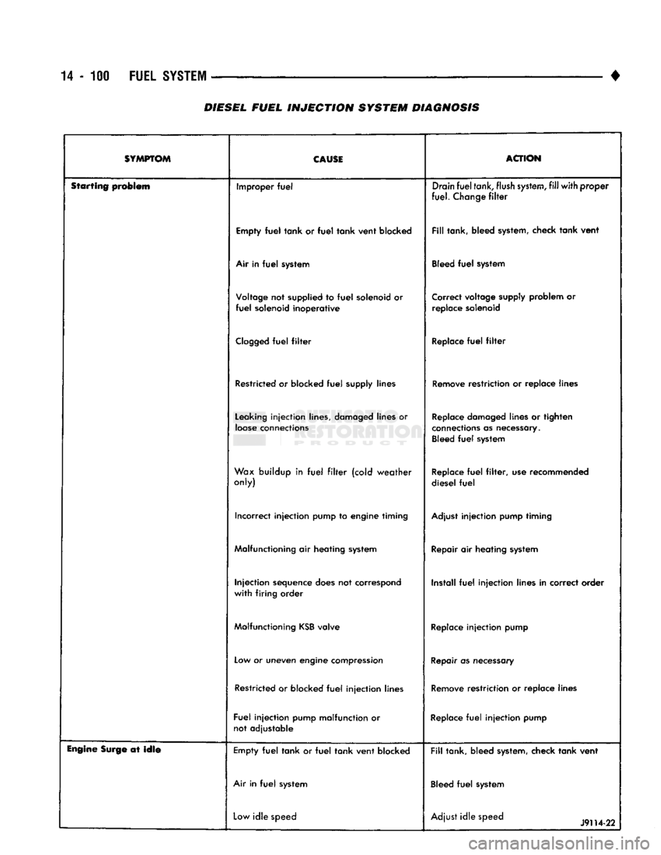
DIESEL
FUEL
INJECTION
SYSTEM DIAGNOSIS
SYMPTOM CAUSE
ACTION
Starting problem Improper
fuel
Drain
fuel
tank,
flush
system,
fill
with
proper
fuel.
Change
filter
Empty
fuel
tank
or
fuel
tank
vent
blocked
Fill
tank, bleed system, check
tank
vent
Air in
fuel
system Bleed
fuel
system
Voltage not supplied to
fuel
solenoid or
fuel
solenoid
inoperative
Correct voltage supply problem or
replace solenoid
Clogged
fuel
filter
Replace
fuel
filter
Restricted or blocked
fuel
supply lines Remove restriction or replace lines
Leaking
injection
lines, damaged lines or
loose
connections Replace damaged lines or tighten
connections as necessary. Bleed
fuel
system
Wax buildup in
fuel
filter
(cold
weather
only) Replace
fuel
filter,
use recommended
diesel
fuel
Incorrect
injection
pump to engine timing Adjust
injection
pump timing
Malfunctioning air heating system Repair air heating system
Injection
sequence does not correspond
with
firing
order Install
fuel
injection
lines in correct order
Malfunctioning
KSB
valve Replace
injection
pump
Low or uneven engine compression Repair as necessary
Restricted or blocked
fuel
injection
lines Remove restriction or replace lines
Fuel
injection
pump malfunction or not adjustable Replace
fuel
injection
pump
Engine
Surge at
idle
Empty
fuel
tank
or
fuel
tank
vent
blocked
Fill
tank, bleed system, check
tank
vent
Air in
fuel
system Bleed
fuel
system
Low
idle
speed Adjust
idle
speed
J9H4-22
Page 920 of 1502
•
FUEL
SYSTEM
14 - 101
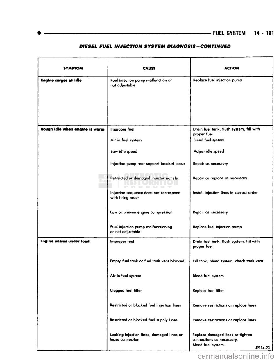
DIESEL FUEL
INJECTION
SYSTEM DIAGNOSIS-CONTINUED
SYMPTOM
CAUSE
ACTION
Engine
surges
at
idle
Fuel
injection
pump malfunction or
not adjustable Replace
fuel
injection
pump
Rough
idle
when engine Is warm Improper
fuel
Air in
fuel
system Drain
fuel
tank, flush system,
fill
with
proper
fuel
Bleed
fuel
system
Low
idle
speed Adjust
idle
speed
Injection
pump
rear
support bracket loose Repair as necessary
Restricted or damaged
injector
nozzle
Repair or replace as necessary
Injection
sequence does not correspond
with
firing
order Install
injection
lines in correct order
Low or uneven engine compression Repair as necessary
Fuel
injection
pump malfunctioning
or not adjustable Replace
fuel
injection
pump
Engine
mines under lead Improper
fuel
Drain
fuel
tank, flush system,
fill
with
proper
fuel
Empty
fuel
tank
or
fuel
tank
vent
blocked
Fill
tank, bleed system, check
tank
vent
Air in
fuel
system Bleed
fuel
system
Clogged
fuel
filter
Replace
fuel
filter
Restricted or blocked
fuel
injection
lines Remove restrictions or replace lines
Restricted or blocked
fuel
supply lines Remove restrictions or replace lines
Leaking
injection
lines, damaged lines or
loose
connection Replace damaged lines or
tighten
connections as necessary. Bleed
fuel
system. 1
J9114-23
Page 921 of 1502
14
- 102
FUEL
SYSTEM
—
•
SYMPTOM
CAUSI
ACTION
lupin*
mimes under Im4 Incorrect
injection
pump
timing
Adjust
injection
pump
timing
Restricted
or
damaged
injector
nozzle
Replace
or
repair
as
necessary
Restricted
or
blocked
fuel
injection
lines Install
fittings
proper positions
Fuel
Injection
pump malfunction
or
not adjustable
Replace
fuel
injection
pump
lew power Improper
fuel
Drain
fuel
tank, flush
system,
fill
with
proper
fuel
Empty
fuel
tank or
fuel
tank vent blocked
Fill
tank, bleed
system,
check tank vent
Control lever not going
to full throttle
position Adjust
throttle
linkage
Clogged
fuel
filter
Replace
fuel
filter
Intercooler
internally
blocked
or
leaking
Check
pressure
drop
across
intercooler.
If
pressure
drop is more than
4
in.
Hg,
clean
or replace
as
necessary.
Restricted
or
blocked
fuel
supply lines
Remove
restrictions
or
replace lines
Injection
pump overflow
fitting
switched
with
inlet
fitting
Install
fittings
in
proper positions
Leaking
injection
lines, damaged lines
or
loose
connections
Replace
damaged
lines
or
tighten
connections
as
necessary.
Bleed
fuel
system
Incorrect
injection
pump
to
engine
timing
Adjust
injection
pump
timing
Restricted or
damaged
injector
nozzle
Repair
or replace as
necessary
Clogged
or
restricted
air filter
Remove
restrictions
or
replace
filter if
necessary
Air
fuel
control
tube broken
or
leaking
Repair
or replace
as
necessary
Low
manifold pressure
Check
and repair turbocharger operation.
Check
intercooler and
air
pipes
for
blockage
Injection
sequence
does
not correspond
with
firing
order Install
fuel
injection
lines in correct
order
Low
or
uneven
engine
compression
Repair
as
necessary
Restricted or blocked
fuel
injection
lines
Remove
restrictions
or
replace lines
Incorrect
injection
pump
to
engine
timing
Check
injection
pump
to
engine
timing
Fuel
injection
pump malfunction
or
not adjustable
Replace
fuel
injection
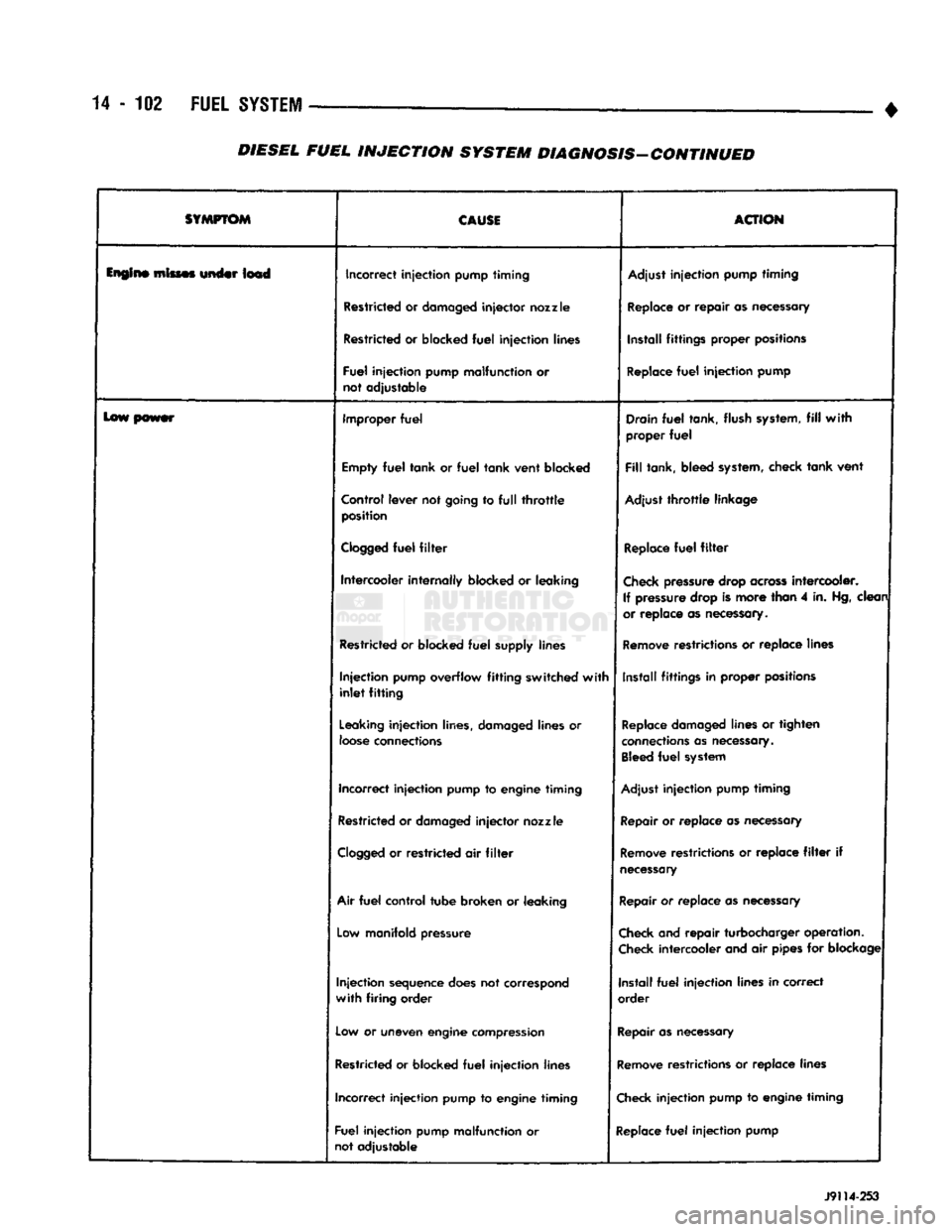
pump J9114-253
DIESEL
FUEL
INJECTION
SYSTEM
DIAGNOSIS-CONTINUED