1993 DODGE TRUCK air filter
[x] Cancel search: air filterPage 612 of 1502
•
ENGINES
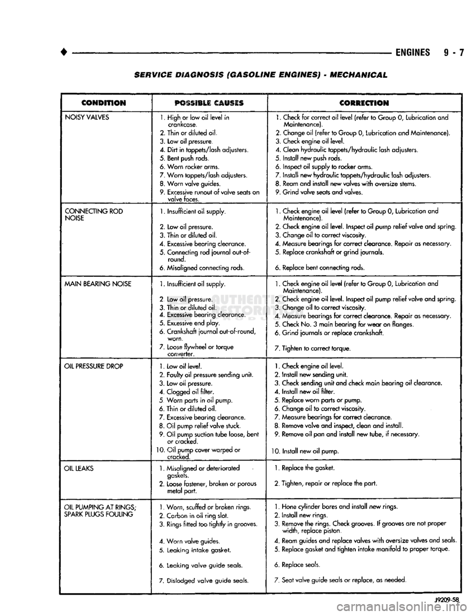
9 - 7 SERVICE DIAGNOSIS (GASOLINE ENGINES) - MECHANICAL
CONDITION
PSSSI1LI
CAUSIS
CORRECTION
NOISY
VALVES
1. High
or
low oil
level
in
crankcase.
2. Thin or
diluted
oil.
3.
Low
oil
pressure.
4.
Dirt
in
tappets/lash
adjusters.
5. Bent
push
rods.
6. Worn rocker arms.
7.
Worn
tappets/lash
adjusters.
8.
Worn
valve
guides.
9.
Excessive
runout
of
valve
seats
on
valve
faces.
1.
Check
for
correct oil
level
(refer
to
Group
0,
Lubrication and
Maintenance).
2. Change oil
(refer
to Group
0,
Lubrication and Maintenance).
3. Check engine oil level.
4. Clean hydraulic tappets/hydraulic lash adjusters.
5. Install new
push
rods.
6. Inspect oil supply to rocker arms.
7. Install new hydraulic tappets/hydraulic lash adjusters. 8. Ream and install new valves
with
oversize stems.
9. Grind valve seats and valves.
CONNECTING
ROD
NOISE
1.
Insufficient oil supply.
2.
Low oil
pressure.
3.
Thin
or
diluted
oil.
4.
Excessive
bearing
clearance.
5. Connecting rod
journal
out-of- round.
6. Misaligned connecting rods.
1.
Check engine oil
level
(refer
to Group
0,
Lubrication and
Maintenance).
2. Check engine oil level. Inspect oil pump
relief
valve and spring.
3. Change oil to correct
viscosity.
4. Measure bearings for correct clearance. Repair as necessary, 5. Replace crankshaft or grind journals.
6.
Replace
bent
connecting rods.
MAIN
BEARING
NOISE
1.
Insufficient oil supply.
2 Low
oil
pressure.
3. Thin or
diluted
oil.
4.
Excessive
bearing clearance. 5.
Excessive
end play.
6. Crankshaft
journal
out-of-round, worn,
7.
Loose
flywheel
or
torque
converter.
1.
Check engine oil
level
(refer
to Group
0,
Lubrication and
Maintenance).
2. Check engine oil level. Inspect oil pump
relief
valve and spring.
3. Change oil to correct
viscosity.
4. Measure bearings for correct clearance. Repair as necessary. 5. Check No.
3
main bearing for
wear
on flanges.
6. Grind journals
or
replace crankshaft.
7. Tighten to correct torque.
OIL
PRESSURE
DROP
1.
Low oil level.
2. Faulty oil pressure sending
unit.
3. Low
oil
pressure.
4.
Clogged
oil
filter.
5 Worn parts in
oil
pump.
6. Thin or
diluted
oil.
7.
Excessive
bearing clearance. 8.
Oil
pump
relief
valve stuck.
9. Oil pump suction
tube
loose,
bent
or cracked.
10.
Oil pump cover warped
or
cracked.
1.
Check engine oil level.
2. Install new sending
unit.
3. Check sending
unit
and check main bearing oil clearance.
4. Install new oil
filter.
5. Replace worn parts or pump. 6. Change oil to correct
viscosity.
7. Measure bearings for correct clearance.
8. Remove valve and inspect, clean and install. 9. Remove oil pan and install new tube,
if
necessary.
10. Install new oil pump.
OIL
LEAKS
1.
Misaligned or
deteriorated
gaskets.
2.
Loose
fastener, broken
or
porous
metal
part.
1. Replace the gasket.
2. Tighten,
repair
or replace the
part.
OIL
PUMPING
AT
RINGS;
SPARK
PLUGS
FOULING
1.
Worn, scuffed
or broken
rings.
2. Carbon in oil ring
slot.
3.
Rings
fitted
too
tightly
in grooves.
4. Worn valve guides.
5. Leaking
intake
gasket.
6. Leaking valve guide
seals.
7. Dislodged valve guide
seals.
1.
Hone cylinder bores and install new rings.
2. Install new rings.
3. Remove the rings. Check
grooves.
If
grooves
are not proper width, replace piston.
4. Ream guides and replace valves
with
oversize valves and
seals.
5. Replace gasket and tighten
intake
manifold
to
proper torque.
6. Replace
seals.
7. Seat
valve guide
seals
or
replace, as needed.
J9209-58
Page 613 of 1502
9
- 8
ENGINES
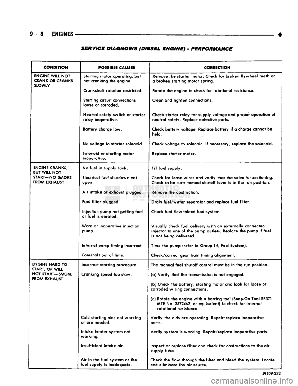
• SERVICE DIAGNOSIS (DIESEL ENGINE) - PERFORMANCE
CONDITION
POSSIBLE
CAUSES
COtiECTION
ENGINE
WILL
NOT
CRANK
OR
CRANKS
SLOWLY
Starting
motor operating, but
not cranking the engine.
Crankshaft
rotation restricted.
Starting
circuit
connections
loose
or corroded.
Neutral safety switch or starter
relay inoperative.
Battery charge low.
No
voltage to starter
solenoid.
Solenoid
or starting motor inoperative.
Remove
the starter motor. Check for broken flywheel
teeth
or
a
broken starting motor
spring.
Rotate the engine to check for rotational resistance.
Clean
and tighten
connections.
Check
starter relay for
supply
voltage and proper operation of neutral safety. Replace defective parts.
Check
battery voltage. Replace battery if a charge cannot be
held.
Check
voltage to
solenoid.
If
necessary,
replace the
solenoid.
Replace
starter motor.
ENGINE
CRANKS,
BUT
WILL
NOT
START—NO
SMOKE
FROM
EXHAUST
No
fuel
in supply tank.
Electrical
fuel
shutdown not
open.
Air
intake or exhaust
plugged.
Fuel
filter
plugged.
Injection pump not getting
fuel
or
fuel
is aerated.
Worn
or inoperative injection
pump.
Internal pump timing incorrect.
Camshaft
out of time.
Fill
fuel
supply.
Check
for
loose
wires and verify that the valve is functioning.
Check
to be sure manual shutoff lever is in the run position.
Remove
the obstruction.
Drain
fuel/water separator and replace
fuel
filter.
Check
fuel
flow/bleed
fuel
system.
Visually
check
fuel
delivery with an externally connected injector to one of the pump outlets. Replace the pump if
fuel
is
not being delivered.
Time the pump
(refer
to Group 14, Fuel
System).
Check/correct
gear train timing alignment.
ENGINE
HARD
TO
START,
OR
WILL
NOT
START—SMOKE
FROM
EXHAUST
Incorrect starting procedure.
Cranking
speed too
slow.
Cold
starting
aids
not working
or
are needed.
Intake heater
system
not
working.
Insufficient intake air.
Air
in the
fuel
system
or the
fuel
supply is inadequate. The manual
fuel
shutoff control must be in the run position.
(a) Verify that the
transmission
is not
engaged.
(b) Check the battery, starting motor and look for
loose
or
corroded
wiring
connections.
(c) Rotate the engine with a barring tool
(Snap-On
Tool
SP371,
MTE
No. 3377462, or equivalent) to check for internal rotational resistance.
Verify the
aids
are operating. Repair/replace inoperative
parts.
Verify
system
is working. Repair/replace inoperative parts.
Inspect
or replace
filter
and check for
obstructions
to the air
supply
tube.
Check
the flow through the
filter
and bleed the
system.
Locate
and
eliminate the air source. J9109-232
Page 614 of 1502
•
ENGINES
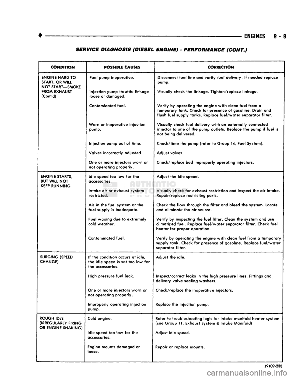
9 - 9 SERVICE DIAGNOSIS (DIESEL ENGINE) • PERFORMANCE (CONT.)
CONDITION
POSSIBLE
CAUSES
CORRECTION
ENGINE
HARD
TO
START,
OR
WILL
NOT
START—SMOKE
FROM
EXHAUST
(Cont'd)
Fuel pump Inoperative.
Injection pump
throttle
linkage
loose
or
damaged.
Contaminated
fuel.
Worn
or inoperative injection
pump.
Injection pump out of time.
Valves
incorrectly adjusted.
One
or more injectors worn or not operating properly.
Disconnect
fuel
line and verify
fuel
delivery. If needed replace
pump.
Visually
check the linkage. Tighten/replace linkage.
Verify by operating the engine with clean
fuel
from a temporary tank. Check for presence of
gasoline.
Drain and
flush
fuel
supply tanks.
Replace
fuel/water separator
filter.
Visually
check
fuel
delivery with an externally connected injector to one of the pump outlets. Replace the pump if
fuel
is
not being delivered.
Check/time
the pump
(refer
to Group 14, Fuel
System).
Adjust
valves.
Check/replace
bad improperly operating injectors.
ENGINE
STARTS,
BUT
WILL
NOT
KEEP
RUNNING
Idle speed too low for the
accessories.
Intake air or exhaust
system
restricted.
Air
in the
fuel
system
or the
fuel
supply is inadequate.
Fuel waxing due to extremely
cold
weather.
Contaminated
fuel.
Adjust
the idle
speed.
Visually
check for exhaust restriction and inspect the air intake.
Repair/replace restricting parts.
Check
the flow through the
filter
and bleed the
system.
Locate
and
eliminate the air source.
Verify by inspecting the
fuel
filter.
Clean the
system
and use
climatized fuel. Replace fuel/water separator
filter.
Check
fuel
heater for proper operation.
Verify by operating the engine with clean
fuel
from a temporary
supply
tank. Check for presence of
gasoline.
Replace fuel/water
separator
filter.
SURGING
(SPEED
CHANGE)
If the condition
occurs
at idle,
the idle speed is set too low for
the
accessories.
High
pressure
fuel
leak.
One
or more injectors worn or not operating properly.
Improperly operating injection
pump.
Adjust
the idle.
Inspect/correct
leaks in the high pressure lines. Fittings and
delivery valve
sealing
washers.
Check/replace
the inoperative injectors.
Replace
the injection pump.
ROUGH
IDLE
(IRREGULARLY
FIRING
OR
ENGINE
SHAKING)
Cold
engine.
Idle speed too low for the
accessories.
Engine
mounts
damaged
or
loose.
Refer to troubleshooting
logic
for intake manifold heater
system
(see
Group 11,
Exhaust
System
& Intake Manifold)
Adjust
idle
speed.
Repair
or replace mounts. J9109-233
Page 615 of 1502
9
- 10
ENGINES
— _
•
CONDITION
possmu
CLOSES
CORRECTION
ROUGH
IDLE
(IRREGULARLY
FIRING
OR
ENGINE
SHAKING)
(Cont'd)
High
pressure
fuel
leaks.
Air In the
fuel
system.
Correct leaks in the high pressure lines, fittings or
delivery
valves.
Bleed the
fuel
system and
eliminate
the source of the air.
Sticking
needle
valve
in an
injector.
Check and replace the
injector
with
the sticking
needle
valve.
ENGINE
RUNS
ROUGH
OR
MISFIRING
Fuel
injection
lines
leaking.
Correct leaks in the high pressure lines, fittings,
injector
sealing
washers
or
delivery
valves.
Air in the
fuel
or the
fuel
supply
is
inadequate.
Check the flow through the
filter
and bleed the system. Locate
and
eliminate
the air source.
Contaminated
fuel.
Verify
by operating the engine
with
clean
fuel
from a temporary
supply
tank. Check for presence of gasoline. Replace
fuel/water
separator
filter.
Incorrect
valve
adjustment.
Check for a
bent
push rod and adjust valves. Replace push rod,
if necessary.
Injection
pump
timing
incorrect.
Check/time pump
(refer
to Group 14,
Fuel
System).
Improperly
operating
injectors.
Replace inoperative injectors.
Defective
injection
pump
(delivery
valves).
Replace
injection
pump.
Camshaft
out of
time.
Check/correct gear
train
timing alignment.
Damaged
camshaft or
tappets.
Inspect camshaft valve
lift.
Replace camshaft and tappets.
ENGINE
RPM WILL NOT
REACH
RATED
SPEED
Engine
overloaded.
Verify
high
idle
speed
without
load. Investigate operation to be
sure correct gear is being used.
Improperly
operating
tachometer.
Verify
engine speed
with
hand tachometer—correct as required.
Throttle
linkage
worn
or
incorrectly
adjusted.
Adjust linkage for stop-to-stop
fuel
control
lever
travel.
Replace
linkage if necessary.
Partially
engaged
mechanical
shutdown
lever.
Adjust and place shutdown
lever
in the run position.
Inadequate
fuel
supply. Check the
fuel
flow through the system to locate the reason for
inadequate
fuel
supply—correct as required.
Improperly
operating
injection
pump.
Replace
injection
pump.
LOW
POWER
Fuel
control
lever
not
moving
to
full
throttle.
Check/correct for stop-to-stop
travel.
Mechanical/shutdown
lever
partially
engaged.
Check to see if the shutdown
lever
is in run position.
High
oil
level.
Check/correct oil level.
Engine
overloaded.
Check for added loading from accessories or driven units, brakes
dragging
and
other
changes in vehicle loading. Repair/replace as
needed.
J9109-264
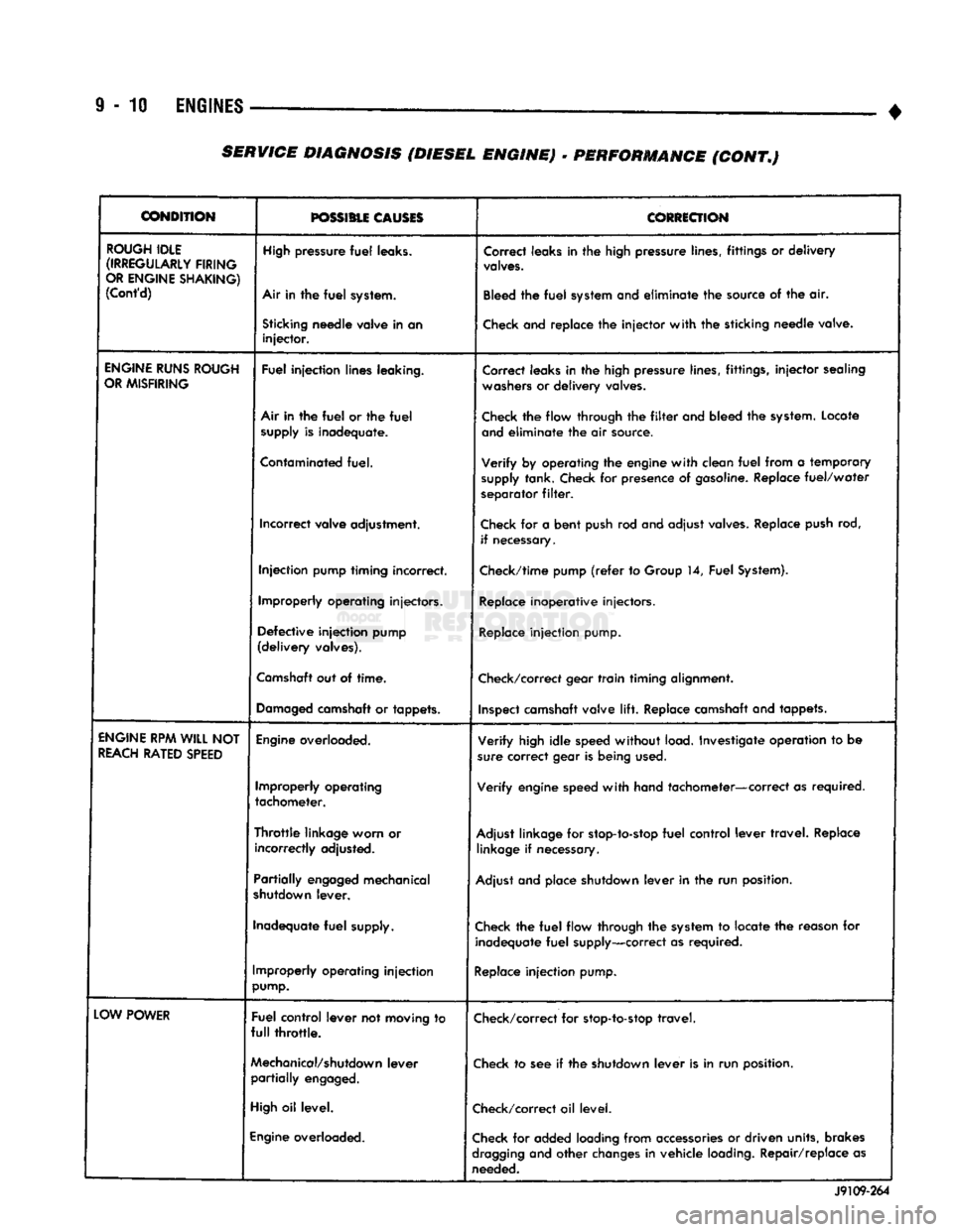
SERVICE
DIAGNOSIS (DIESEL ENGINE)
•
PERFORMANCE (CONT.)
Page 616 of 1502
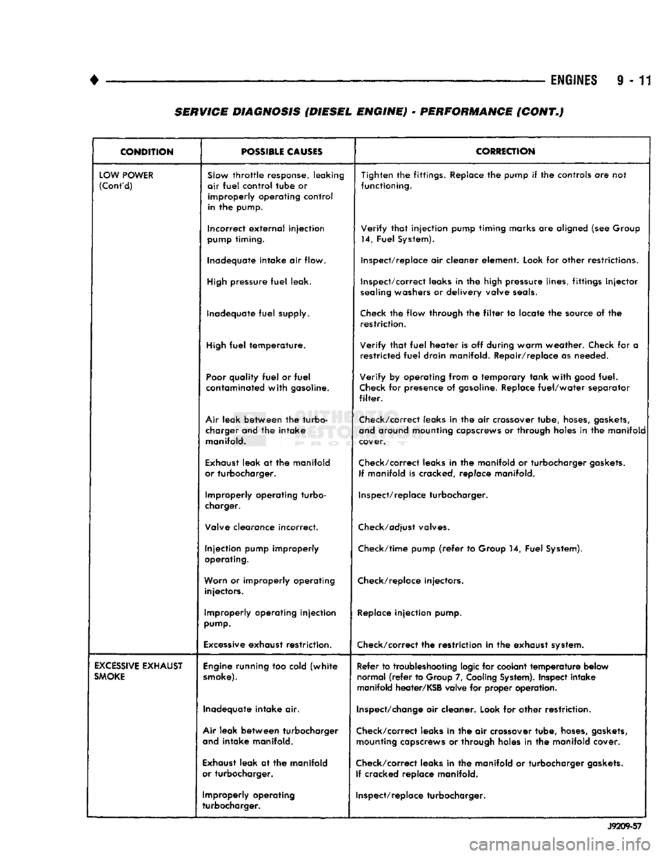
•
ENGINES
9 - 11 SERVICE DIAGNOSIS (DIESEL ENGINE) - PERFORMANCE (CONT.)
CONDITION
POSSIBLE
CAUSES
CORRECTION
LOW
POWER
(Cont'd)
SJow
throttle
response, leaking
air
fuel
control
tube
or
improperly
operating
control
in the pump. Tighten the fittings. Replace the pump if the controls are not
functioning.
Incorrect
external
injection
pump
timing. Verify
that
injection pump timing marks are aligned (see Group
14, Fuel System).
Inadequate intake air flow. Inspect/replace air cleaner element. Look for other restrictions.
High
pressure
fuel
leak. Inspect/correct leaks in the high pressure lines, fittings
injector
sealing
washers or delivery valve
seals.
Inadequate
fuel
supply.
Check
the flow through the
filter
to locate the source of the
restriction.
High
fuel
temperature. Verify
that
fuel
heater is off during warm weather. Check for a
restricted
fuel
drain manifold. Repair/replace as needed.
Poor
quality
fuel
or
fuel
contaminated
with
gasoline. Verify by operating from a temporary tank
with
good
fuel.
Check
for presence of
gasoline.
Replace
fuel/water
separator
filter.
Air
leak between the turbo- charger and the intake manifold. Check/correct leaks in the air crossover tube,
hoses,
gaskets,
and
around mounting capscrews or through holes in the manifold
cover.
Exhaust
leak at the manifold
or turbocharger. Check/correct leaks in the manifold or turbocharger
gaskets.
If manifold is cracked, replace manifold.
Improperly operating turbo-
charger. Inspect/replace turbocharger.
Valve clearance incorrect.
Check/adjust
valves.
Injection pump improperly
operating. Check/time pump
(refer
to Group 14, Fuel System).
Worn
or improperly operating injectors. Check/replace injectors.
Improperly operating injection
pump.
Replace
injection pump.
Excessive
exhaust restriction. Check/correct the restriction in the exhaust system.
EXCESSIVE
EXHAUST
SMOKE
Engine
running too cold
(white
smoke).
Refer to troubleshooting logic for coolant
temperature
below
normal
(refer
to Group 7,
Cooling
System).
Inspect intake
manifold heater/KSB valve for proper operation.
Inadequate intake air.
Inspect/change
air cleaner. Look for other restriction.
Air
leak between turbocharger
and
intake manifold. Check/correct leaks in the air crossover tube,
hoses,
gaskets,
mounting capscrews or through holes in the manifold cover.
Exhaust
leak at the manifold
or turbocharger. Check/correct leaks in the manifold or turbocharger
gaskets.
If cracked replace manifold.
Improperly operating
turbocharger. Inspect/replace turbocharger.
J9209-57
Page 620 of 1502
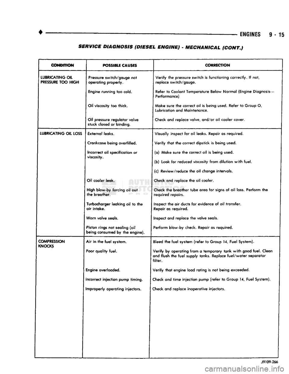
•
• —
ENGINES
9 - 15
CONDITION
POSSIBLE CAUSES
CORRECTION
LUBRICATING
OIL
PRESSURE
TOO
HIGH
Pressure
switch/gauge
not
operating
properly.
Verify
the
pressure
switch
is
functioning
correctly.
If not,
replace
switch/gauge.
Engine
running
too
cold.
Refer
to
Coolant
Temperature
Below
Normal
(Engine
Diagnosis-
Performance)
Oil
viscosity
too thick. Make
sure
the
correct
oil Is
being
used.
Refer
to
Group
O,
Lubrication
and
Maintenance.
Oil
pressure
regulator
valve
stuck
closed
or
binding.
Check
and replace valve, and/or oil cooler cover.
LUBRICATING
OIL
LOSS
External
leaks.
Visually
inspect for oil
leaks.
Repair as required.
Crankcase
being
overfilled. Verify that the correct dipstick is being
used.
incorrect
oil specification or
viscosity.
(a) Make sure the correct oil is being
used.
(b)
Look
for reduced
viscosity
from dilution with fuel.
(c) Review/reduce the oil
change
intervals.
Oil
cooler
leak.
Check
and replace the oil cooler.
High
blow-by
forcing oil out
the breather.
Check
the breather tube area for
signs
of oil
loss.
Perform the
required repairs.
Turbocharger
leaking
oil to the
air intake.
Inspect
the air
ducts
for evidence of oil transfer.
Repair
as required.
Worn
valve
seals.
Inspect
and replace the valve
seals.
Piston
rings
not
sealing
(oil
being
consumed
by the
engine).
Perform
blow-by check. Repair as required.
COMPRESSION
KNOCKS
Air in the
fuel
system.
Poor
quality
fuel.
Bleed
the fuel
system
(refer
to
Group
14, Fuel
System).
Verify by operating from a temporary tank with
good
fuel. Clean
and
flush the fuel
supply
tanks.
Replace fuel/water separator
filter.
Engine
overloaded. Verify that engine load rating is not being exceeded.
Incorrect injection
pump
timing.
Check
and time injection pump
(refer
to
Group
14, Fuel
System).
Improperly
operating
injectors.
Check
and replace inoperative injectors. J9109-266 SERVICE DIAGNOSIS (DIESEL ENGINE) - MECHANICAL (CONT.)
Page 717 of 1502
9
- 112 5.9L
(DIESEL)
ENGINE
• (5) Position the engine in the chassis and install
the through bolt. Tighten the through bolt nut to 41
N-m (30 ft. lbs.) torque. (6) Make sure the lifting brackets are mounted
with the eye down. (7) Remove the covers or tape covering the engine
openings. (8) Connect the fuel lines to the lift pump and fuel
return.
(9) Connect all electrical connections.
(10) Connect the power steering lines.
(11) Raise and support the vehicle on a hoist.
(12) AUTOMATIC TRANSMISSION:
CAUTION:
If new
flex
plate is installed, remove
flashing
from the engine
back
plate at the 5 and 7
o'clock
positions.
(a) Rotate converter until alignment mark on the
converter is aligned with mark on drive plate.
Off
set holes in plate are next to 1/8 inch hole in inner
circle of drive plate.
(b) Install bell housing bolts. Tighten the bolts to
41 N-m (30 ft. lbs.) torque. (c) With the torque converter plate aligned to the
torque converter, install and tighten the bolts to 31 N-m (270 in. lbs.) torque. (d) Install the converter housing access plate.
(e) Remove the transmission support.
(13) MANUAL TRANSMISSION:
Refer to Group 21, Transmissions for the G360
Manual Transmission Installation procedure. (14) Connect the ground cable and tighten the nut
to 22 N-m (16 ft. lbs.) torque. Connect the solenoid cable and tighten the nut to 5 N-m (44 in. lbs.)
torque.
(15) Connect the transmission cooler lines.
(16) Install the exhaust pipe to the exhaust sys
tem.
(17) Lower the vehicle.
(18) Install the A/C compressor and tighten the
bolts to 47 N-m (35 ft. lbs.) torque. If removed, con nect the clutch electrical wire.
(19) Install the generator. Tighten the upper
mounting bolts to 24 N-m (18 ft. lbs.) torque. Now
tighten the lower mounting bolts to 43 N-m (32 ft. lbs.) torque. Connect all wires.
(20) Install the radiator, fan/fan clutch assembly
and fan shroud (refer to Group 7, Cooling Systems
for the proper procedures). Connect the radiator
hoses.
(21) Position the intercooler inlet duct to the tur
bocharger and the intercooler. With the clamps in po sition, tighten the clamp nut to 8 N-m (72 in. lbs.)
torque. (22) Position the intercooler outlet duct to the air
inlet housing and the intercooler. With the clamps in
position, tighten the clamp nut to 8 N-m (72 in. lbs.)
torque.
(23) Connect the air intake tube to the turbo
charger inlet flange and the air cleaner housing.
Tighten the clamps to 8 N-m (72 in. lbs.) torque. (24) Install the exhaust pipe to the turbocharger.
Tighten the steady rest clamp to 8 N-m (72 in. lbs.) torque.
(25) Make sure the air intake and exhaust pipe
connections are tight and free of leaks.
(26) Fill the engine with the required amount of
clean engine lubricating oil (refer to Group 0, Lubri cation and Maintenance).
(27) Fill the cooling system with a mixture of 50%
water and 50% ethylene-glycol base antifreeze (refer Group 7, Cooling System for the proper procedure).
(28) Install the battery and connect the battery ca
bles.
(29) Check the oil level after the engine has run
for 2 or 3 minutes. Oil held in the oil filter and oil passages will cause the oil level in the pan to be lower.
(30) Operate the engine at idle for 5 to 10 minutes
and check for leaks and loose parts.
ROCKER LEVERS
/
POSH
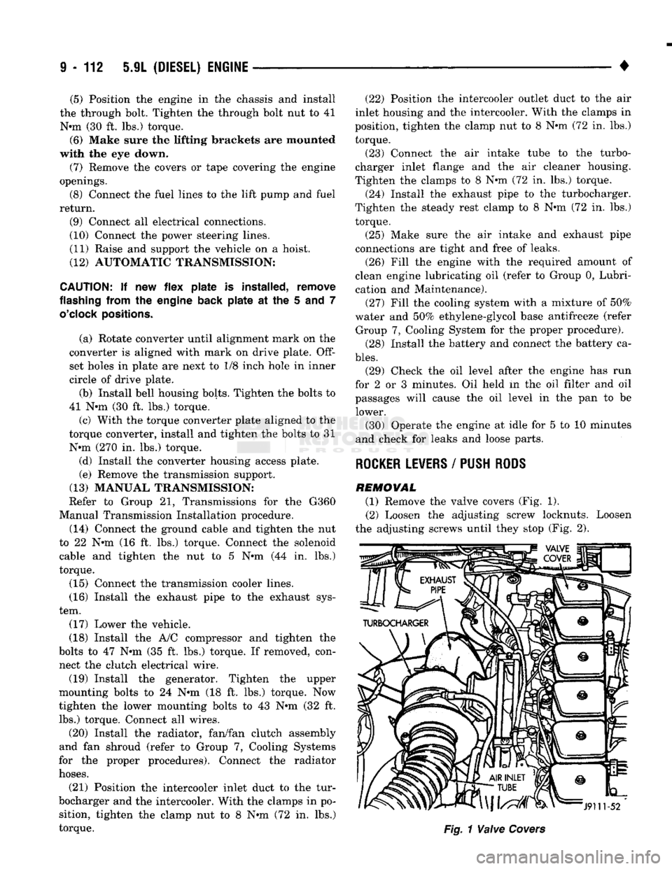
RODS
REMOVAL (1) Remove the valve covers (Fig. 1). (2) Loosen the adjusting screw locknuts. Loosen
the adjusting screws until they stop (Fig. 2).
Page 719 of 1502
9
- 114 5.9L
(DIESEL) ENGINE
—
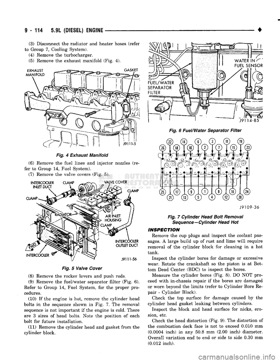
Fig.
4
Exhaust
Manifold
(6) Remove the fuel lines and injector nozzles (re
fer to Group 14, Fuel System).
(7) Remove the valve covers (Fig. 5).
Fig.
5
Valve
Cover
(8) Remove the rocker levers and push rods.
(9) Remove the fuel/water separator filter (Fig. 6).
Refer to Group 14, Fuel System, for the proper pro
cedures.
(10) If the engine is hot, remove the cylinder head
bolts in the sequence shown in Fig. 7..The removal sequence is not important if the engine is cold. There
are 3 sizes of head bolts. Note the position of each
bolt for future installation.
(11) Remove the cylinder head and gasket from the
cylinder block.
•
Fig. 6 Fuel/Water Separator Filter J9109-36
Fig. 7 Cylinder Head Bolt Removal Sequence—Cylinder Head Hot
INSPECTION
Remove the cup plugs and inspect the coolant pas
sages.
A large build up of rust and lime will require
removal of the cylinder block for cleaning in a hot
tank.
Inspect the cylinder bores for damage or excessive
wear. Rotate the crankshaft so the piston is at Bot
tom Dead Center (BDC) to inspect the bores. Measure the cylinder bores (Fig. 8). DO NOT pro
ceed with in-chassis repair if the bores are damaged
or worn beyond the limits (refer to Cylinder Bore Re
pair - Cylinder Block).
Check the top surface for damage caused by the
cylinder head gasket leaking between cylinders.
Inspect the block and head surface for nicks, ero
sion, etc. Check the head distortion (Fig. 9). The distortion of
the combustion deck face is not to exceed 0.010 mm (0.0004 inch) in any 50.8 mm (2.00 inch) diameter.
Overall variation end to end or side to side 0.30 mm (0.012 inch).
(3) Disconnect the radiator and heater hoses (refer
to Group 7, Cooling System). (4) Remove the turbocharger.
(5) Remove the exhaust manifold (Fig. 4).