1993 DODGE TRUCK air filter
[x] Cancel search: air filterPage 864 of 1502
•
FUEL
SYSTEM
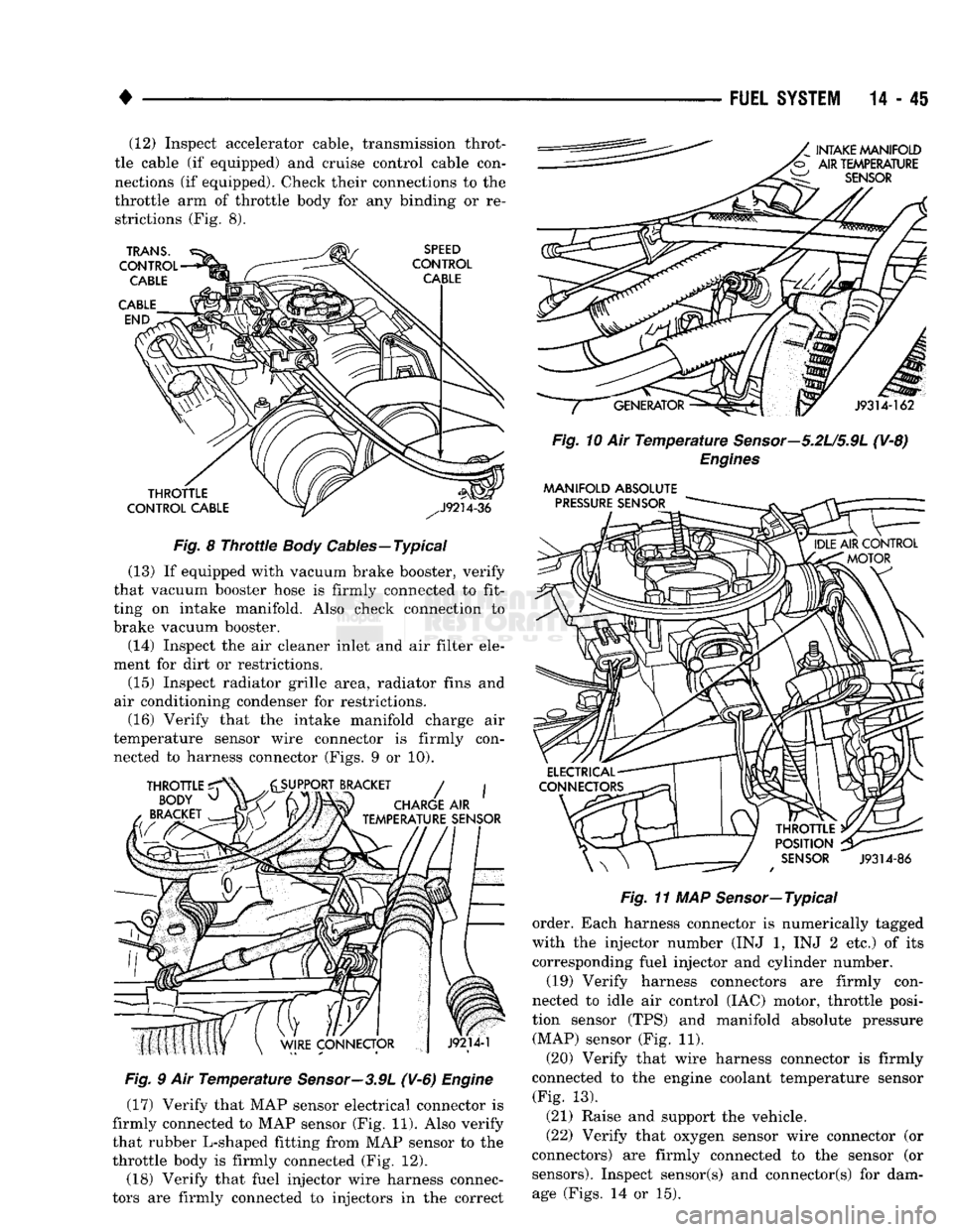
14-45 (12) Inspect accelerator cable, transmission throt
tle cable (if equipped) and cruise control cable con
nections (if equipped). Check their connections to the
throttle arm of throttle body for any binding or re strictions (Fig. 8).
Fig.
8
Throttle
Body
Cables—Typical
(13) If equipped with vacuum brake booster, verify
that vacuum booster hose is firmly connected to fit
ting on intake manifold. Also check connection to
brake vacuum booster.
(14) Inspect the air cleaner inlet and air filter ele
ment for dirt or restrictions.
(15) Inspect radiator grille area, radiator fins and
air conditioning condenser for restrictions. (16) Verify that the intake manifold charge air
temperature sensor wire connector is firmly con nected to harness connector (Figs. 9 or 10).
Fig.
9 Air
Temperature
Sensor—3.9L
(V-6)
Engine
(17) Verify that MAP sensor electrical connector is
firmly connected to MAP sensor (Fig. 11). Also verify
that rubber L-shaped fitting from MAP sensor to the
throttle body is firmly connected (Fig. 12).
(18) Verify that fuel injector wire harness connec
tors are firmly connected to injectors in the correct
Fig.
10 Air
Temperature
Sensor—5.2U5.9L
(V-8)
Engines
MANIFOLD
ABSOLUTE
Fig.
11 MAP Sensor—Typical
order. Each harness connector is numerically tagged
with the injector number (INJ 1, INJ 2 etc.) of its
corresponding fuel injector and cylinder number.
(19) Verify harness connectors are firmly con
nected to idle air control (IAC) motor, throttle posi
tion sensor (TPS) and manifold absolute pressure (MAP) sensor (Fig. 11).
(20) Verify that wire harness connector is firmly
connected to the engine coolant temperature sensor (Fig. 13).
(21) Raise and support the vehicle.
(22) Verify that oxygen sensor wire connector (or
connectors) are firmly connected to the sensor (or sensors). Inspect sensor(s) and connector(s) for damage (Figs. 14 or 15).
Page 878 of 1502
•
FUEL SYSTEM
14 - 59
fill
DHADn
HIAf5MflCTipQ
/f|Rn
The powertrain control module (PCM) has been
programmed to monitor many different circuits of the
fuel injection system. If a problem is sensed in a monitored circuit often enough to indicate an actual
problem, a diagnostic trouble code (DTC) is stored.
The DTC will be stored in the PCM memory for eventual display to the service technician. If the
problem is repaired or ceases to exist, the PCM can cels the DTC after 51 engine starts.
Certain criteria must be met for a diagnostic trou
ble code (DTC) to be entered into PCM memory. The criteria may be a specific range of engine rpm, en
gine temperature and/or input voltage to the PCM.
It is possible that a DTC for a monitored circuit
may not be entered into memory even though a mal
function has occurred. This may happen because one
of the DTC criteria for the circuit has not been met. Example: assume that one of the criteria for the
MAP sensor circuit is that the engine must be oper ating between 750 and 2000 rpm to be monitored for
a DTC. If the MAP sensor output circuit shorts to
ground when the engine rpm is above 2400 rpm, a 0
volt input will be seen by the PCM. A DTC will not
be entered into memory because the condition does not occur within the specified rpm range.
A DTC indicates that the powertrain control mod
ule (PCM) has recognized an abnormal signal in a
circuit or the system. A DTC may indicate the result
of a failure, but never identify the failed component
directly.
There are several operating conditions that the
PCM does not monitor and set a DTC for. Refer to
the following Monitored Circuits and Non-Monitored Circuits in this section.
MONITORED
CIRCUITS
The powertrain control module (PCM) can detect
certain problems in the fuel injection system.
Open or Shorted Circuit - The PCM can deter
mine if sensor output (which is the input to PCM) is
within proper range. It also determines if the circuit is open or shorted.
Output Device Current Flow - The PCM senses
whether the output devices are hooked up.
If there is a problem with the circuit, the PCM
senses whether the circuit is open, shorted to ground
(-), or shorted to
(
+
)
voltage.
Oxygen Sensor - The PCM can determine if the
oxygen sensor is switching between rich and lean.
This is, once the system has entered Closed Loop. Re fer to Open Loop/Closed Loop Modes Of Operation in
the Component Description/System Operation section
for an explanation of Closed (or Open) Loop opera tion.
NON-MONITORED CIRCUITS
The PCM does not monitor the following circuits,
systems or conditions that could have malfunctions
that result in driveability problems. A diagnostic trouble code (DTC) may not be displayed for these
conditions.
Fuel Pressure: Fuel pressure is controlled by the
vacuum assisted fuel pressure regulator. The PCM
cannot detect a clogged fuel pump inlet filter, clogged
in-line fuel filter, or a pinched fuel supply or return
line.
However, these could result in a rich or lean
condition causing an oxygen sensor DTC to be stored in the PCM.
Secondary Ignition Circuit: The PCM cannot de
tect an inoperative ignition coil, fouled or worn spark
plugs,
ignition cross firing, or open circuited spark
plug cables.
Engine Timing: The PCM cannot detect an incor
rectly indexed timing chain, camshaft sprocket or crankshaft sprocket. The PCM also cannot detect an
incorrectly indexed distributor. However, these could
result in a rich or lean condition causing an oxygen
sensor DTC to be stored in the PCM.
Cylinder Compression: The PCM cannot detect
uneven, low, or high engine cylinder compression.
Exhaust System: The PCM cannot detect
a
plugged, restricted or leaking exhaust system.
Fuel Injector Malfunctions: The PCM cannot de
termine if the fuel injector is clogged, or the wrong injector is installed. However, these could result in a
rich or lean condition causing an oxygen sensor DTC
to be stored in the PCM.
Excessive Oil Consumption: Although the PCM
monitors exhaust stream oxygen content through ox
ygen sensor (closed loop), it cannot determine exces sive oil consumption.
Throttle Body Air Flow: The PCM cannot detect
a clogged or restricted air cleaner inlet or air filter
element.
Evaporative System: The PCM will not detect a
restricted, plugged or loaded EVAP canister. Vacuum Assist: Leaks or restrictions in the vac
uum circuits of vacuum assisted engine control sys
tem devices are not monitored by the PCM. However, a vacuum leak at the MAP sensor will be monitored
and a diagnostic trouble code (DTC) will be gener
ated by the PCM.
Powertrain Control Module (PCM) System
Ground: The PCM cannot determine a poor system
ground. However, a DTC may be generated as a re
sult of this condition.
Powertrain Control Module (PCM) Connector
Engagement: The PCM cannot determine spread or
damaged connector pins. However, a DTC may be generated as a result of this condition.
Page 883 of 1502
MULTI-PORT
FUEL
INJECTION
(MPI)-COMPONENT
REMOVAL/INSTALLATION
—EXCEPT DIESEL
INDEX
page
Accelerator Pedal
and Throttle
Cable
. 64
Air Conditioning (A/C) Clutch Relay
64
Air
Filter/Filter
Housing
64
Automatic Shut Down (ASD) Relay
. 64
Brake
Switch
64
Camshaft
Position
Sensor
..................
64
Charge
Air
Temperature
Sensor
64
Crankshaft Position
Sensor
64
Engine
Coolant Temperature
Sensor
65
EVAP
Canister Purge Solenoid
65
Fuel
Filter
65
Fuel Filter/Fuel Pressure Regulator—5.9L Engine
. 65
Fuel Injector(S)
67
Fuel Pressure Regulator
67
Fuel Pump Module
68
Fuel Pump Relay
68
ACCELERATOR
PEDAL
AND THROTTLE
CABLE
Refer
to
the
Accelerator Pedal
and
Throttle Cable
section
of
this group
for
removal/installation proce
dures.
AIR
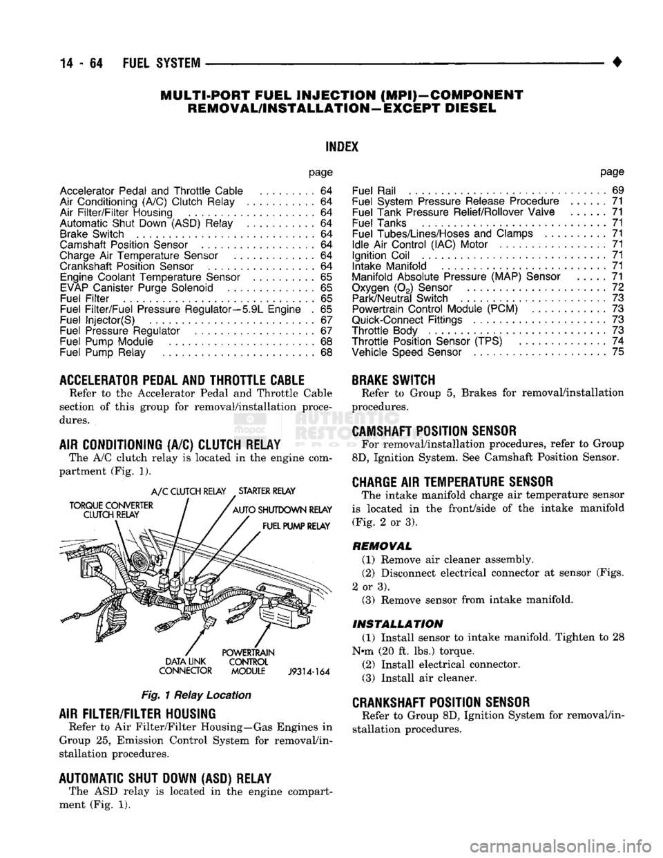
CONDITIONING (A/C) CLUTCH RELAY The A/C clutch relay
is
located
in
the
engine com
partment (Fig.
1).
A/C CLUTCH RELAY STARTER RELAY
DATA LINK CONTROL
CONNECTOR MODULE
J9314-164
Fig.
1 Relay Location
AIR
FILTER/FILTER
HOUSING
Refer
to
Air Filter/Filter Housing—Gas Engines
in
Group
25,
Emission Control System
for
removal/in
stallation procedures.
AUTOMATIC SHUT DOWN (ASD) RELAY The ASD relay
is
located
in
the
engine compart
ment (Fig.
1).
page
Fuel Rail
69
Fuel System Pressure Release Procedure
......
71
Fuel Tank Pressure Relief/Rollover Valve
71
Fuel Tanks
71
Fuel
Tubes/Lines/Hoses
and
Clamps
71
Idle
Air
Control (IAC) Motor
71
Ignition Coil
71
Intake Manifold
71
Manifold Absolute Pressure (MAP)
Sensor
71
Oxygen
(02)
Sensor
72
Park/Neutral Switch
. 73
Powertrain Control Module (PCM)
73
Quick-Connect
Fittings
73
Throttle
Body
73
Throttle
Position
Sensor
(TPS)
......
74
Vehicle
Speed
Sensor
75
BRAKE
SWITCH
Refer
to
Group
5,
Brakes
for
removal/installation
procedures.
CAMSHAFT
POSITION
SENSOR
For removal/installation procedures, refer
to
Group
8D,
Ignition System. See Camshaft Position Sensor.
CHARGE
AIR
TEMPERATURE SENSOR
The intake manifold charge
air
temperature sensor
is located
in the
front/side
of
the
intake manifold (Fig.
2
or
3).
REMOVAL
(1) Remove
air
cleaner assembly.
(2) Disconnect electrical connector
at
sensor (Figs.
2
or
3). (3) Remove sensor from intake manifold.
INSTALLATION
(1) Install sensor
to
intake manifold. Tighten
to 28
Nnn (20
ft.
lbs.) torque.
(2) Install electrical connector.
(3) Install
air
cleaner.
CRANKSHAFT
POSITION
SENSOR
Refer
to
Group 8D, Ignition System
for
removal/in
stallation procedures.
Page 884 of 1502
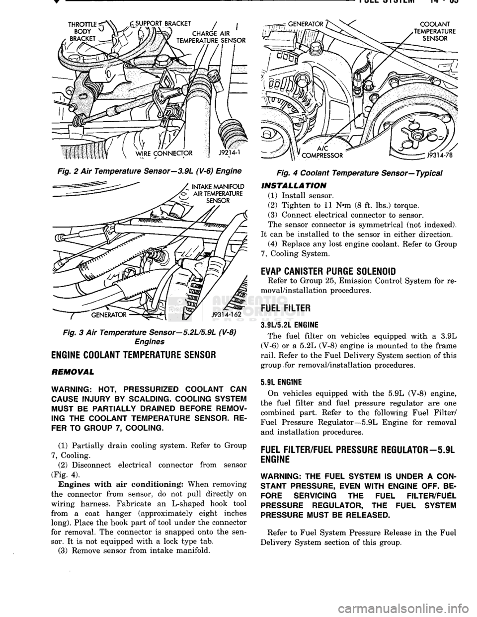
Fig. 2 Ait Temperature Sensor—3.9L (¥-6) Engine
Fig. 3 Air Temperature Sensor—5.2U5.9L (V-8)
Engines
ENGINE
COOLANT
TEMPERATURE
SENSOR
REMOVAL
WARNING:
HOT,
PRESSURIZED COOLANT
CAN
CAUSE
INJURY
BY
SCALDING- COOLING SYSTEM MUST
BE
PARTIALLY DRAINED BEFORE REMOV
ING
THE
COOLANT TEMPERATURE
SENSOR.
RE
FER
TO
GROUP
7,
COOLING.
(1) Partially drain cooling system. Refer to Group
7,
Cooling. (2) Disconnect electrical connector from sensor
(Fig. 4).
Engines with air conditioning: When removing
the connector from sensor, do not pull directly on
wiring harness. Fabricate an L-shaped hook tool from a coat hanger (approximately eight inches
long).
Place the hook part of tool under the connector
for removal. The connector is snapped onto the sen sor. It is not equipped with a lock type tab.
(3) Remove sensor from intake manifold. Fig. 4 Coolant Temperature Sensor—Typical
INSTALLATION
(1) Install sensor.
(2) Tighten to 11 Nnn (8 ft. lbs.) torque.
(3) Connect electrical connector to sensor.
The sensor connector is symmetrical (not indexed).
It can be installed to the sensor in either direction. (4) Replace any lost engine coolant. Refer to Group
7,
Cooling System.
E¥AP
CANISTER
PURGE
SOLENOID
Refer to Group 25, Emission Control System for re
moval/installation procedures.
FUEL
FILTER
3.9L/5.21.
ENGINE
The fuel filter on vehicles equipped with a 3.9L
(V-6) or a 5.2L (V-8) engine is mounted to the frame
rail.
Refer to the Fuel Delivery System section of this
group for removal/installation procedures.
5.91 ENGINE
On vehicles equipped with the 5.9L (V-8) engine,
the fuel filter and fuel pressure regulator are one combined part. Refer to the following Fuel Filter/
Fuel Pressure Regulator—5.9L Engine for removal and installation procedures.
FUEL
FILTER/FUEL
PRESSURE
REGULATOR—5JL
ENGINE
WARNING:
THE FUEL SYSTEM IS UNDER A
CON
STANT
PRESSURE,
EVEN
WITH
ENGINE OFF. BE
FORE
SERVICING THE FUEL FILTER/FUEL
PRESSURE
REGULATOR, THE FUEL SYSTEM
PRESSURE
MUST BE
RELEASED.
Refer to Fuel System Pressure Release in the Fuel
Delivery System section of this group.
Page 887 of 1502
14
- 68
FUEL
SYSTEM
•
SNAP
RING
SNAP
RING
PLIERS
VACUUM
LINE
PROTECTIVE CAP
FUEL
PRESSURE
REGULATOR,
FUEL RAIL
J9214-47
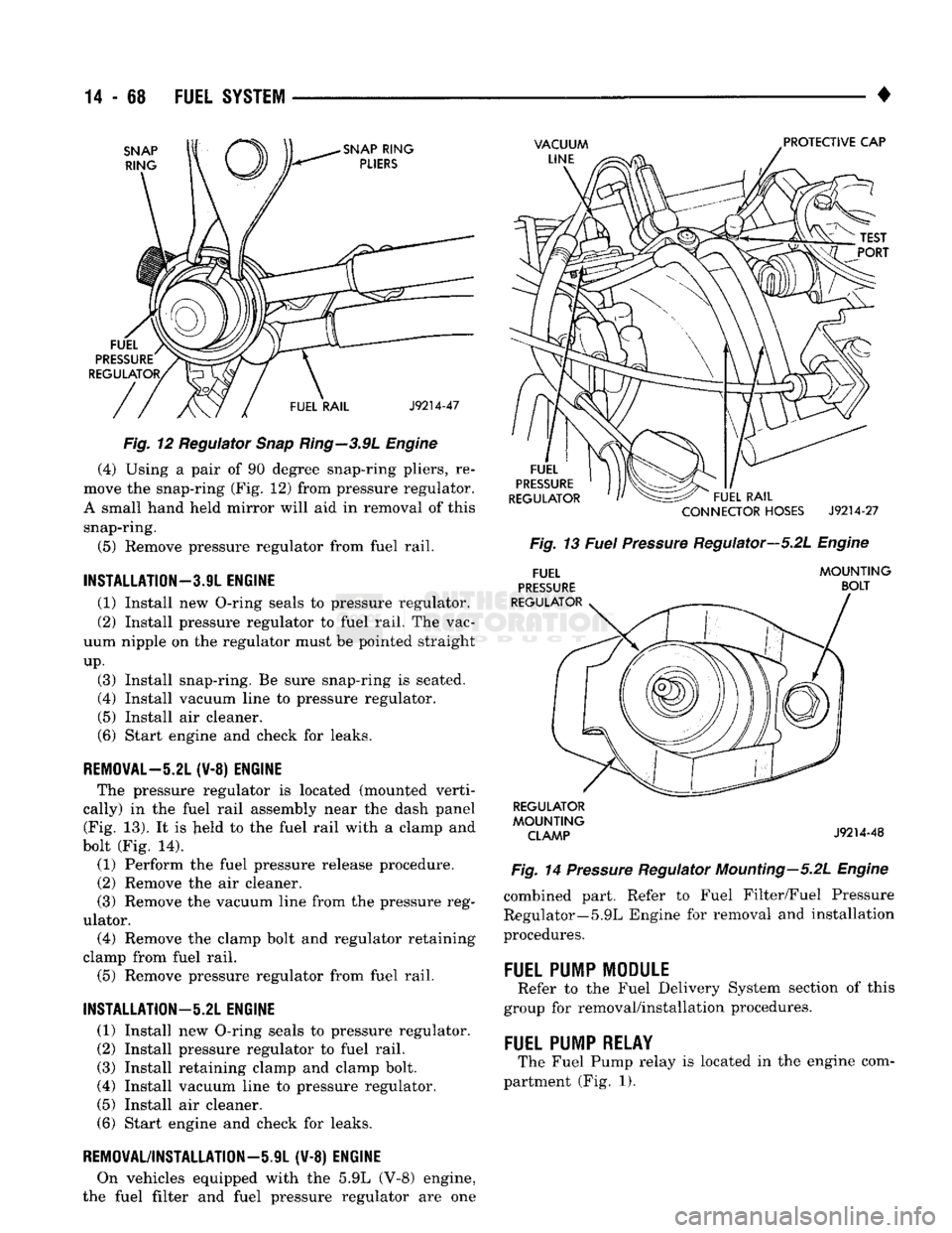
Fig. 12 Regulator Snap Ring—3.9L Engine (4) Using a pair of 90 degree snap-ring pliers, re
move the snap-ring (Fig. 12) from pressure regulator.
A small hand held mirror will aid in removal of this snap-ring.
(5) Remove pressure regulator from fuel rail.
INSTALLATION—3.9L
ENGINE
(1) Install new O-ring seals to pressure regulator.
(2) Install pressure regulator to fuel rail. The vac
uum nipple on the regulator must be pointed straight
up.
(3) Install snap-ring. Be sure snap-ring is seated.
(4) Install vacuum line to pressure regulator.
(5) Install air cleaner.
(6) Start engine and check for leaks.
REMOVAL-5.21
(¥-8) ENGINE The pressure regulator is located (mounted verti
cally) in the fuel rail assembly near the dash panel (Fig. 13). It is Jield to the fuel rail with a clamp and
bolt (Fig. 14).
(1) Perform the fuel pressure release procedure.
(2) Remove the air cleaner.
(3) Remove the vacuum line from the pressure reg
ulator. (4) Remove the clamp bolt and regulator retaining
clamp from fuel rail.
(5) Remove pressure regulator from fuel rail.
INSTALLATION—5.2L
ENGINE
(1) Install new O-ring seals to pressure regulator.
(2) Install pressure regulator to fuel rail. (3) Install retaining clamp and clamp bolt.
(4) Install vacuum line to pressure regulator.
(5) Install air cleaner.
(6) Start engine and check for leaks.
REMOVAL/INSTALLATION—iJL (V-8) ENGINE
On vehicles equipped with the 5.9L (V-8) engine,
the fuel filter and fuel pressure regulator are one
FUEL
PRESSURE
REGULATOR FUEL RAIL
CONNECTOR
HOSES
J9214-27
Fig. 13 Fuel Pressure Regulator—5.2L Engine
FUEL
PRESSURE
REGULATOR MOUNTING
BOLT REGULATOR
MOUNTING CLAMP
J9214-48
Fig. 14 Pressure Regulator Mounting—5.2L Engine combined part. Refer to Fuel Filter/Fuel Pressure
Regulator—5.9L Engine for removal and installation
procedures.
FUEL
PUMP
MODULE
Refer to the Fuel Delivery System section of this
group for removal/installation procedures.
FUEL
PUMP
RELAY
The Fuel Pump relay is located in the engine com
partment (Fig. 1).
Page 890 of 1502
•
FUEL SYSTEM
14-71
FUEL SYSTEM PRESSURE RELEASE PROCEDURE
WARNING:
THE
FUEL
SYSTEM
IS
UNDER
A
CON
STANT
PRESSURE
(EVEN
WITH
THE
ENGINE
TURNED
OFF).
BEFORE
SERVICING
THE
FUEL
PUMP,
FUEL
LINES
(TUBES),
FUEL
FILTER,
OR
FUEL
INJECTOR(S),
THE
FUEL
SYSTEM
PRESSURE
MUST
BE
RELEASED.
To release fuel pressure, refer to the Fuel Delivery
System section of this group. See Fuel System Pres
sure Release Procedure.
FUEL TANKS
Refer to the Fuel Tank section of this group for re
moval/installation procedures.
FUEL TANK
PRESSURE
RELIEF/ROLLOVER VALVE
Refer to the Fuel Tank section of this group for re
moval/installation procedures.
FUEL
TUBES/LINES/HOSES
AND CLAMPS
Refer to Fuel Tubes/Lines/Hoses and Clamps in the
Fuel Delivery System section of this group for remov al/installation procedures. Also refer to Quick-Connect Fittings in the Fuel
Delivery System section of this group for removal/in
stallation procedures.
IDLE
AIR
CONTROL
(IAC)
MOTOR
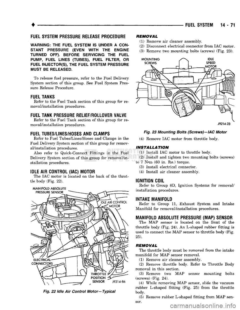
The IAC motor is located on the back of the throt
tle body (Fig. 22).
MANIFOLD ABSOLUTE
Fig.
22
idle
Air Control Motor—Typical
REMOVAL
(1) Remove air cleaner assembly.
(2) Disconnect electrical connector from IAC motor.
(3) Remove two mounting bolts (screws) (Fig. 23).
J9214-23
Fig.
23
Mounting
Bolts
(Screws)—IAC
Motor
(4) Remove IAC motor from throttle body.
INSTALLATION
(1) Install IAC motor to throttle body.
(2) Install and tighten two mounting bolts (screws)
to 7 N»m (60 in. lbs.) torque.
(3) Install electrical connector.
(4) Install air cleaner assembly.
IGNITION COIL
Refer to Group 8D, Ignition Systems for removal/
installation procedures.
INTAKE MANIFOLD
Refer to Group 11, Exhaust System and Intake
Manifold for removal/installation procedures.
MANIFOLD ABSOLUTE
PRESSURE
(MAP)
SENSOR
The MAP sensor is located on the front of the
throttle body (Fig. 24). An L-shaped rubber fitting is
used to connect the MAP sensor to throttle body (Fig.
25).
REMOVAL
The throttle body must be removed from the intake
manifold for MAP sensor removal.
(1) Remove air cleaner assembly.
(2) Remove throttle body. Refer to Throttle Body
removal in this section.
(3) Remove two MAP sensor mounting bolts
(screws) (Fig. 24). (4) While removing MAP sensor, slide the vacuum
rubber L-shaped fitting (Fig. 25) from the throttle
body.
(5) Remove rubber L-shaped fitting from MAP sen
sor.
Page 895 of 1502
DIESEL
FUEL
INJECTION—COMPONENT
DESCRIPTION/SYSTEM
OPERATION
NDEX
page
Air
Conditioning (A/C) Clutch
Relay-PCM
Output
. 81
Air
Conditioning (A/C)
Controls-PCM
Input
.... 77
Air
Intake Heater
Relays—PCM
Output
........ 81
Auto
Shut
Down
(ASD)
Relay-PCM
Output
.... 82
Automatic
Shut
Down
(ASD)
Sense-PCM
input
. 78
Battery
Voltage-PCM
Input
78
Brake
Switch—PCM
Input
....... 78
Charge
Air
Temperature
Sensor—PCM
Input
... 78
Engine
Speed
Sensor—PCM
Input
........... 78
Fuel
Drain Manifold
83
Fuel
Heater
83
Fuel
Injection
Pump
83
Fuel
Injectors
84
Fuel
Solenoid
84
Fuel/Water
Separator
Filter ................. 84
General
Information
76
Generator
Field-PCM
Output
. 81
High
Pressure
Fuel
Lines
85
Ignition
Sense—PCM
Input
78
KSB
Solenoid
....... 85
Malfunction Indicator
Lamp—PCM
Output
...... 82
Manual
Shut
Down
Lever
.................. 85
GENERAL
INFORMATION
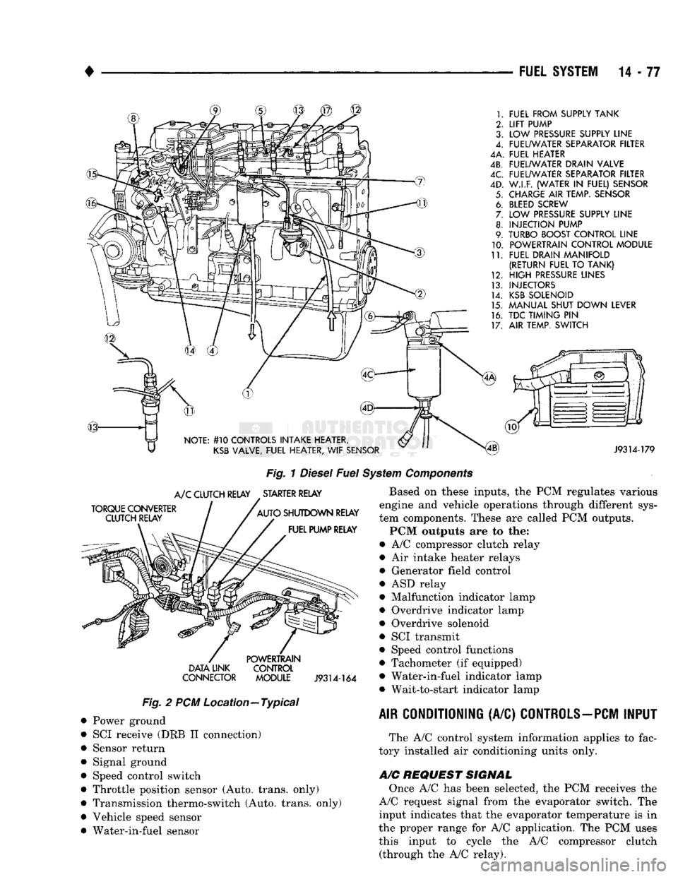
The fuel system of the 5.9L (in-line six-cylinder)
turbo-diesel engine (Fig. 1) consists of the following components:
• Fuel tank
• Low and high pressure fuel supply lines
• Mechanical lift pump
• Fuel/water separator filter
• Fuel heater
• Fuel injection pump
• Fuel injectors • Fuel return lines For information regarding fuel requirements of the
5.9L turbo-diesel engine, refer to the Fuel Require
ments—Diesel Engines paragraph at the front of this group. Although various components, relays and switches
are operated by the powertrain control module (PCM), the diesel fuel injection system (Fig. 1) is not
directly regulated by the PCM. Refer to the proceed
ing Powertrain Control Module section for additional
information.
SYSTEM
DIAGNOSIS
The PCM tests many of its own input and output
circuits. If a diagnostic trouble code (DTC) is found in a major system, this information is stored in the
PCM memory. Refer to On-Board Diagnostics in the Diesel Fuel Injection—General Diagnosis section of
page
Mechanical
Lift
Pump
86
Overdrive
Indicator
Lamp—PCM
Output
....... 82
Overdrive
Solenoid-PCM
Output
............ 82
Overdrive/Override
Switch—PCM
Input
........ 79
Park/Neutral
Switch-PCM
Input
79
Power
Ground-PCM
Input
. 79
Powertrain Control Module
(PCM)
76
SCI
Receive-PCM
Input
. . 80
SCI
Transmit-PCM
Output
. . . 82
Sensor
Return-PCM
Input
................. 80
Signal
Ground-PCM
Input
. 80
Speed
Control-PCM
Input
80
Speed
Control-PCM
Output
82
System
Diagnosis
76
System
Operation
86
Tachometer-PCM
Output
82
Throttle
Position
Sensor
(TPS)-PCM
Input
80
Vehicle
Speed
Sensor-PCM
Input
80
Wait-To-Start
Lamp-PCM
Output
82
Water-ln-Fuel
Lamp-PCM
Output
83
Water-ln-Fuel
Sensor-PCM
input
80
this group for DTC information. The DRB II scan tool can be used to access the DTC messages stored in the PCM memory.
POWERTRAIN
CONTROL
MODULE
(PCM)
The powertrain control module (PCM) (Fig. 2) was
formerly referred to as the SBEC or engine control ler. The PCM is a pre-programmed, dual micropro
cessor digital computer. The PCM is located in the engine compartment be
hind the battery and under the left front fender (Fig.
2).
The PCM contains a voltage convertor, which con
verts battery voltage to a regulated 8.0 volts. This is used to power the engine speed sensor. The PCM also
provides a 5 volt supply for the throttle position sensor (TPS). The TPS is not used if equipped with a
manual transmission.
Various sensors, switches and relays provide the
inputs necessary for operation of the PCM.
The PCM Inputs are from:
9
Air conditioning control switch
• Automatic shut down (ASD) sense circuit
• Battery voltage
• Brake light switch • Charge air temperature sensor ® Coolant temperature sensor (Auto, trans, only)
• Engine speed sensor
• Ignition
• Overdrive/override switch
• Park/neutral switch (Auto, trans, only)
Page 896 of 1502
•
FUEL
SYSTEM
14-77
FUEL FROM SUPPLY TANK
LIFT
PUMP
LOW
PRESSURE
SUPPLY LINE
FUEL/WATER SEPARATOR FILTER
4A. FUEL HEATER
4B. FUEL/WATER DRAIN VALVE
FUEL/WATER SEPARATOR FILTER
W.I.F. (WATER
IN
FUEL) SENSOR
CHARGE
AIR
TEMP. SENSOR
BLEED
SCREW
LOW
PRESSURE
SUPPLY LINE
INJECTION PUMP
TURBO BOOST CONTROL LINE POWERTRAIN CONTROL MODULE
FUEL DRAIN MANIFOLD
(RETURN FUEL
TO
TANK)
HIGH
PRESSURE
LINES
INJECTORS
KSB
SOLENOID
MANUAL SHUT DOWN LEVER
TDC TIMING
PIN
AIR TEMP. SWITCH
NOTE: #10 CONTROLS INTAKE HEATER,
KSB
VALVE, FUEL HEATER,
WIF
SENSOR
J9314-179
Fig.
1
Diesel
Fuel
System
Components
TORQUE CONVERTER CLUTCH RELAY
A/C
CLUTCH RELAY STARTER RELAY
AUTO SHUTDOWN RELAY FUEL PUMP RELAY DATA UNK
CONNECTOR POWERTRAIN
CONTROL
MODULE
J9314-164
Fig.
2 PCM Location—Typical Power ground
SCI receive (DRB II connection)
Sensor return
Signal ground
Speed control switch
Throttle position sensor (Auto, trans, only)
Transmission thermo-switch (Auto, trans, only)
Vehicle speed sensor
Water-in-fuel sensor Based on these inputs, the PCM regulates various
engine and vehicle operations through different sys
tem components. These are called PCM outputs.
PCM outputs are to the:
• A/C compressor clutch relay
• Air intake heater relays
• Generator field control
• ASD relay
• Malfunction indicator lamp
• Overdrive indicator lamp
• Overdrive solenoid
• SCI transmit
• Speed control functions
• Tachometer (if equipped)
• Water-in-fuel indicator lamp • Wait-to-start indicator lamp
AIR CONDITIONING
(A/C)
CONTROLS-PCM
INPUT
The A/C control system information applies to fac
tory installed air conditioning units only.
A/C
REQUEST SIGNAL
Once A/C has been selected, the PCM receives the
A/C request signal from the evaporator switch. The input indicates that the evaporator temperature is in
the proper range for A/C application. The PCM uses this input to cycle the A/C compressor clutch (through the A/C relay).