1993 DODGE TRUCK air filter
[x] Cancel search: air filterPage 79 of 1502
2
- 26
FRONT
SUSPENSION
AND
AXLE
•
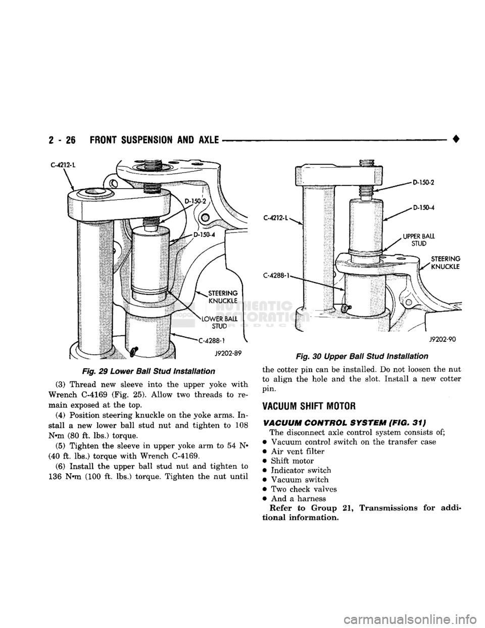
Fig.
29
Lower
Ball
Stud
Installation
(3) Thread new sleeve into the upper yoke with
Wrench C-4169 (Fig. 25). Allow two threads to re
main exposed at the top.
(4) Position steering knuckle on the yoke arms. In
stall a new lower ball stud nut and tighten to 108
Nnn (80 ft. lbs.) torque.
(5) Tighten the sleeve in upper yoke arm to 54 N*
(40 ft. lbs.) torque with Wrench C-4169.
(6) Install the upper ball stud nut and tighten to
136 Nnn (100 ft. lbs.) torque. Tighten the nut until C-4212-L
C-4288-1
J9202-90
Fig.
30 Upper
Ball
Stud
Installation
the cotter pin can be installed. Do not loosen the nut
to align the hole and the slot. Install a new cotter
pin.
VACUUM
SHIFT
MOTOR
VACUUM
CONTROL
SYSTEM
(FIG. 31) The disconnect axle control system consists of;
• Vacuum control switch on the transfer case • Air vent filter
• Shift motor
• Indicator switch
• Vacuum switch
• Two check valves • And a harness Refer to Group 21, Transmissions for addi
tional information.
Page 306 of 1502
•
COOLING
SYSTEM
7 - 35
HOSE
CLAMP TOOL
6094
HOSE
CLAMP
J9207-36
Fig.
48
Hose
damp Tool
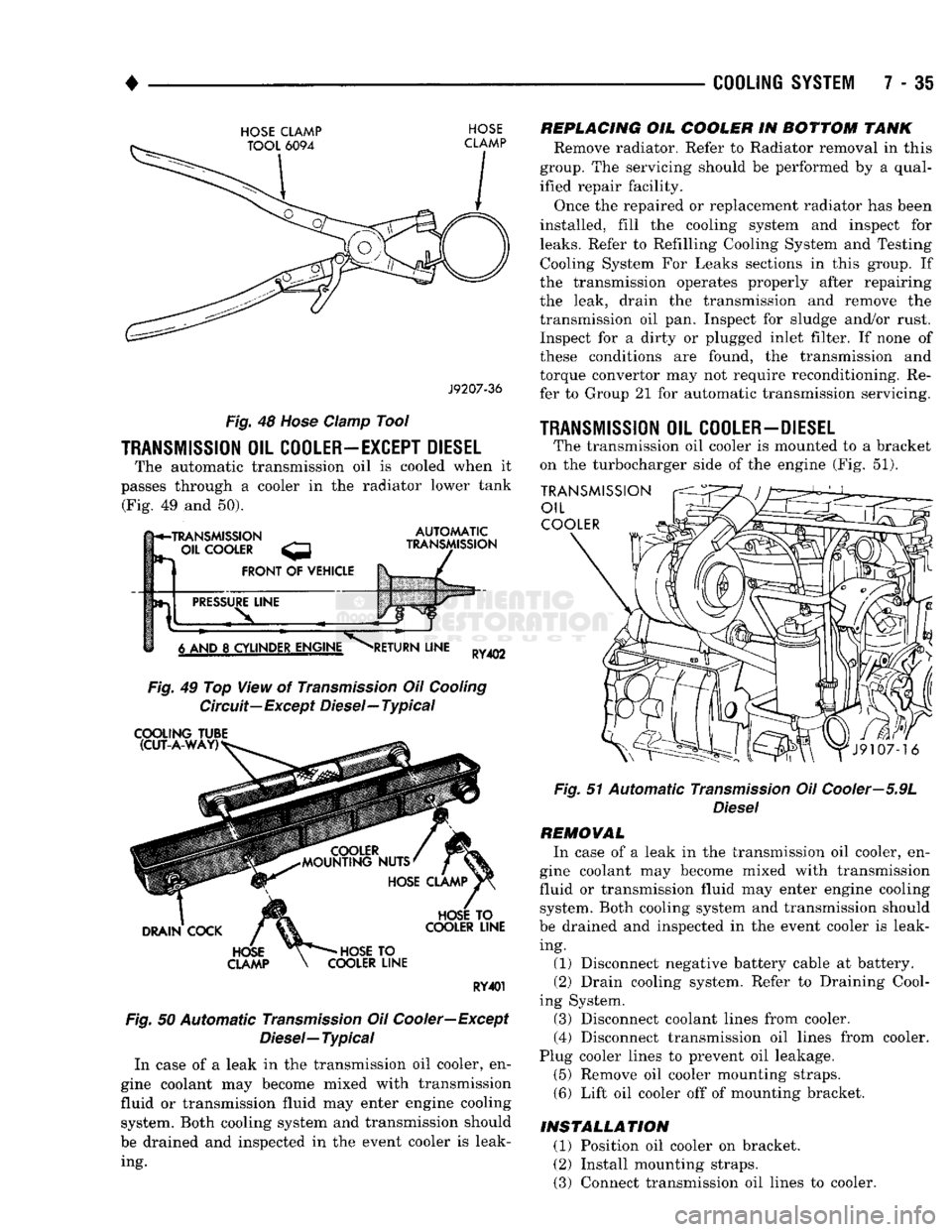
TRANSMISSION
OIL
COOLER—EXCEPT DIESEL
The automatic transmission oil is cooled when it
passes through a cooler in the radiator lower tank (Fig. 49 and 50).
h*-TRANSMISSION
- OIL
COOLER
FRONT
OF
VEHICLE
AUTOMATIC
TRANSMISSION
PRESSURE
LINE
6 AND
8
CYLINDER ENGINE
RETURN
LINE
RY402
Fig.
49 Top View of
Transmission
Oil
Cooling
Circuit—Except Diesel—Typical
COOLING
TUBE (CUT-A-WAY)
DRAIN
COCK
HOSE
CLAMP
HOSE
TO
COOLER
LINE
HOSE
TO
COOLER
LINE
RY401
Fig.
50 Automatic
Transmission
Oil Cooler—Except
Diesel—
Typical
In case of a leak in the transmission oil cooler, en
gine coolant may become mixed with transmission
fluid or transmission fluid may enter engine cooling system. Both cooling system and transmission should
be drained and inspected in the event cooler is leak ing.
REPLACING
OIL
COOLER
IN
BOTTOM
TANK
Remove radiator. Refer to Radiator removal in this
group. The servicing should be performed by a qual
ified repair facility.
Once the repaired or replacement radiator has been
installed, fill the cooling system and inspect for
leaks.
Refer to Refilling Cooling System and Testing Cooling System For Leaks sections in this group. If
the transmission operates properly after repairing
the leak, drain the transmission and remove the
transmission oil pan. Inspect for sludge and/or rust. Inspect for a dirty or plugged inlet filter. If none of
these conditions are found, the transmission and
torque convertor may not require reconditioning. Re
fer to Group 21 for automatic transmission servicing.
1RANSMISSI0N
OIL
COOLER-DIESEL
The transmission oil cooler is mounted to a bracket
on the turbocharger side of the engine (Fig. 51).
TRANSMISSION
OIL
COOLER
Fig.
51 Automatic
Transmission
Oil Cooler—5.9L
Diesel
REMOVAL
In case of a leak in the transmission oil cooler, en
gine coolant may become mixed with transmission
fluid or transmission fluid may enter engine cooling system. Both cooling system and transmission should
be drained and inspected in the event cooler is leak ing. (1) Disconnect negative battery cable at battery.
(2) Drain cooling system. Refer to Draining Cool
ing System. (3) Disconnect coolant lines from cooler.
(4) Disconnect transmission oil lines from cooler.
Plug cooler lines to prevent oil leakage. (5) Remove oil cooler mounting straps.
(6) Lift oil cooler off of mounting bracket.
INSTALLATION
(1) Position oil cooler on bracket.
(2) Install mounting straps.
(3) Connect transmission oil lines to cooler.
Page 366 of 1502

•
IGNITION
SYSTEMS
8D - 15 J908D-15
Fig.
22 Normal Operation and Cold (Carbon) Fouling
sically carbon (Fig. 22). A dry, black deposit on one
or two plugs in a set may be caused by sticking
valves or defective spark plug cables. Cold (carbon)
fouling of the entire set of spark plugs may be caused
by a clogged air filter or .repeated short operating
times (short trips).
ELECTRODE GAP BRIDGIMG
Electrode gap bridging may be traced to loose de
posits in the combustion chamber. These deposits ac cumulate on the spark plugs during continuous stop-
and-go driving. When the engine is suddenly
subjected to a high torque load, deposits partially liq
uefy and bridge the gap between electrodes (Fig. 28).
This short circuits the electrodes. Spark plugs with electrode gap bridging can be cleaned using standard
procedures.
GROUND
ELECTRODE
J908D-11
Fig. 23 Electrode Gap Bridging
SCAVENGER
DEPOSITS
Fuel scavenger deposits may be either white or yel
low (Fig. 24). They may appear to be harmful, but
this is a normal condition caused by chemical addi
tives in certain fuels. These additives are designed to change the chemical nature of deposits and decrease
spark plug misfire tendencies. Notice that accumula
tion on the ground electrode and shell area may be
heavy, but the deposits are easily removed. Spark
plugs with scavenger deposits can be considered nor mal in condition and can be cleaned using standard
procedures.
GROUND
ELECTRODE
COVERED
J908D-12
Fig.
24
Scavenger
Deposits
CHIPPED ELECTRODE
INSULATOR
A chipped electrode insulator usually results from
bending the center electrode while adjusting the spark plug electrode gap. Under certain conditions, severe detonation can also separate the insulator
from the center electrode (Fig. 25). Spark plugs with
this condition must be replaced.
GROUND
J908D-13
Fig.
25
Chipped
Electrode Insulator
PREIGNITION
DAMAGE
Preignition damage is usually caused by excessive
combustion chamber temperature. The center elec
trode dissolves first and the ground electrode dis solves somewhat latter (Fig. 26). Insulators appear
relatively deposit free. Determine if the spark plug
has the correct heat range rating for the engine. De
termine if ignition timing is over advanced, or if
Page 385 of 1502
8E
- 4
INSTRUMENT PANEL
AND
GAUGES
•
MESSAGE CENTER—DIESEL
ENGINE
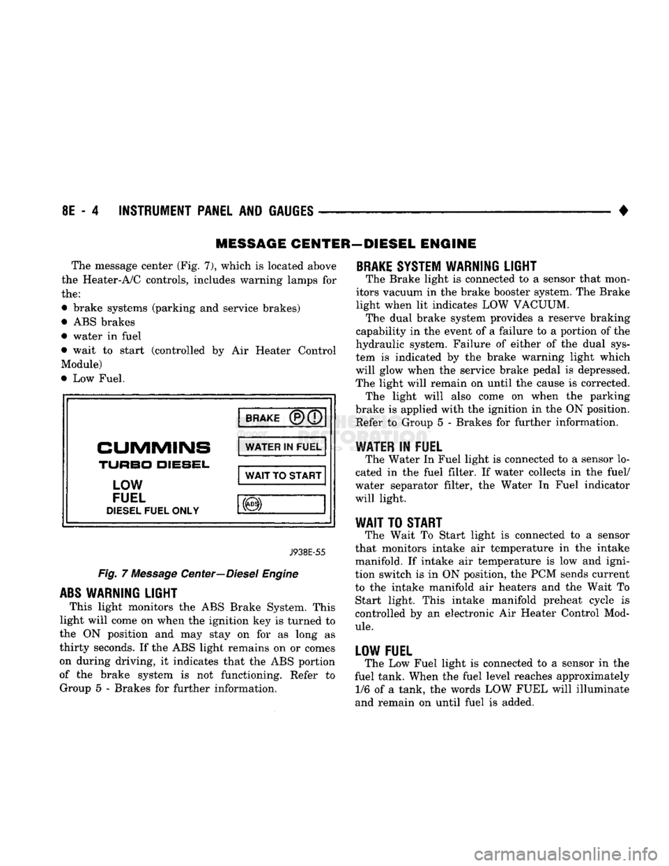
The message center (Fig. 7), which
is
located above
the Heater-A/C controls, includes warning lamps
for
the:
• brake systems (parking
and
service brakes)
• ABS brakes
• water
in
fuel
• wait
to
start (controlled
by Air
Heater Control
Module)
• Low Fuel.
BRAKE
CUMMINS
TURBO
DIESEL,
LOW
FUEL
DIESEL
FUEL ONLY WATER
IN
FUEL
WAIT
TO
START
J938E-55
Fig.
7
Message Center—Diesel Engine
ABS
WARNING LIGHT
This light monitors
the
ABS Brake System. This
light will come
on
when the ignition key
is
turned
to
the
ON
position
and may
stay
on for as
long
as
thirty seconds.
If
the ABS light remains
on or
comes
on during driving,
it
indicates that
the
ABS portion
of
the
brake system
is not
functioning. Refer
to
Group
5 -
Brakes
for
further information.
BRAKE
SYSTEM WARNING LIGHT
The Brake light
is
connected
to a
sensor that mon
itors vacuum
in
the brake booster system. The Brake
light when
lit
indicates LOW VACUUM. The dual brake system provides
a
reserve braking
capability
in
the event
of a
failure
to a
portion
of
the
hydraulic system. Failure
of
either
of the
dual sys
tem
is
indicated
by the
brake warning light which
will glow when
the
service brake pedal
is
depressed.
The light will remain
on
until
the
cause
is
corrected. The light will also come
on
when
the
parking
brake
is
applied with the ignition
in
the ON position. Refer
to
Group
5 -
Brakes
for
further information.
WATER
IN
FUEL
The Water
In
Fuel light
is
connected
to a
sensor lo
cated
in the
fuel filter.
If
water collects
in the
fuel/
water separator filter,
the
Water
In
Fuel indicator
will light.
WAIT
TO
START
The Wait
To
Start light
is
connected
to a
sensor
that monitors intake
air
temperature
in the
intake
manifold.
If
intake
air
temperature
is low and
igni
tion switch
is in
ON position,
the
PCM sends current
to
the
intake manifold
air
heaters
and the
Wait
To
Start light. This intake manifold preheat cycle
is
controlled
by an
electronic
Air
Heater Control Mod
ule.
LOW FUEL
The Low Fuel light
is
connected
to a
sensor
in the
fuel tank. When the fuel level reaches approximately 1/6
of a
tank,
the
words LOW FUEL will illuminate
and remain
on
until fuel
is
added.
Page 541 of 1502
8W - 66 WIRING DIAGRAMS
•
WATER-1N-FUEL
SENSOR
(IN FUEL FILTER)
VEHICLE
SPEED SENSOR
(ON REAR
OF TRANSMISSION
MANUAL TRANSMISSION AND 205
TRANSFER
CASE
CRANKSHAFT POSITION
SENSOR
FRONT OF
ENGINE) INTAKE AIR
TEMPERATURE
SENSOR
IN INTAKE
LEFT SIDE)
TO LEFT
PRINTED CIRCUIT
BOARD
CONNECTOR
[SEE
SH 60)
TO DAYTIME
RUNNING
LIGHT
MODULE
(CANADA ONLY)
(SEE
SH 46)
47 7 2 1 21 24
28
VEHICLE 8 VOLT ECT WATER -1N- INTAKE
CKP
THERMO
SPEED SENSOR
INPUT
SENSOR
FUEL AIR TEMP PICK-UP
SWITCH
PICK-UP
SENSOR
CONNECTOR
POWERTRAIN CONTROL MODULE II (PCM II)
(SEE
SH 83)
(LEFT
FENDER SIDE SHIELD)
AD 25
DIESEL
CONTROL SYSTEM
J938H-11
Page 607 of 1502

9
- 2
ENGINES
rial surrounds each mounting hole. Excess material
can easily be wiped off. Components should be
torqued in place within 15 minutes. The use of a lo cating dowel is recommended during assembly to pre
vent smearing the material off location.
ENGINE PERFORMANCE
To provide best vehicle performance and lowest ve
hicle emissions, it is most important that the tune-up
be done accurately. Use the specifications listed on
the Vehicle Emission Control Information label found on the engine compartment hood.
(1) Test cranking amperage draw (refer to Group
8B,
Battery/Starter/Generator Service for the proper
procedures).
(2) Tighten the intake manifold bolts (refer to
Group 11, Exhaust System and Intake Manifold for
the proper specifications). (3) Perform cylinder compression test:
(a) Check engine oil level and add oil, if neces
sary.
(b) Drive the vehicle until engine reaches normal
operating temperature. (c) Select a route free from traffic and other
forms of congestion, observe all traffic laws and
briskly accelerate through the gears several times. The higher engine speed may help clean out valve seat deposits which can prevent accurate compres
sion readings.
CAUTION:
DO NOT
overspeed
the
engine.
(d) Remove all spark plugs from engine. As
spark plugs are being removed, check electrodes for
abnormal firing indicators - fouled, hot, oily, etc.
Record cylinder number of spark plug for future
reference.
(e) Disconnect coil wire from distributor and se
cure to good ground to prevent a spark from start
ing a fire.
(f) Be sure throttle blades are fully open during
the compression check. (g) Insert compression gage adaptor into the
No.l spark plug hole. Crank engine until maxi
mum pressure is reached on gauge. Record this
pressure as No.l cylinder pressure.
(h) Repeat Step 3g for all remaining cylinders.
(i) Compression should not be less than 689 kPa
(100 psi) and not vary more than 172 kPa (25 psi)
from cylinder to cylinder.
(j) If cylinder(s) have abnormally low compres
sion pressures, repeat steps 3a through 3h. (k) If the same cylinder(s) repeat an abnormally
low reading, it could indicate the existence of a
problem in the cylinder.
The recommended compression pressures are
to be used only as a guide to diagnosing engine
problems. An engine should NOT be disassem bled to determine the cause of low compression
unless some malfunction is present. (4) Clean or replace spark plugs as necessary. Ad
just gap (refer to Group 8D, Ignition System for gap adjustment and torque).
(5) Test resistance of spark plug cables (refer to
Group 8D, Ignition System.
(6) Inspect the primary wire. Test coil output volt
age,
primary and secondary resistance. Replace parts as necessary (refer to Group 8D, Ignition System and
make necessary adjustment).
(7) Set ignition timing to specifications (refer to
Specification Label on engine compartment hood).
(8) Perform a combustion analysis.
(9) Test fuel pump for pressure and vacuum (refer
to Group 14, Fuel System for the proper specifica
tions).
(10) Inspect air filter element (refer to Group 0,
Lubrication and Maintenance for the proper proce
dure).
(11) Inspect crankcase ventilation system (refer to
Group 0, Lubrication and Maintenance for the proper
procedure).
(12) For emission controls refer to Group 25, Emis
sion Controls System for service procedures.
(13) Inspect and adjust accessory belt drives (refer
to Group 7, Cooling System for the proper adjust
ments).
(14) Road test vehicle as a final test.
H0NIN6
CYLINDER
BORES
Before honing, stuff plenty of clean shop towels un
der the bores and over the crankshaft to keep abra sive materials from entering the crankshaft area.
(1) Used carefully, the Cylinder Bore Sizing Hone
C-823 equipped with 220 grit stones, is the best tool
for this job. In addition to deglazing, it will reduce
taper and out-of-round as well as removing light scuffing, scoring or scratches. Usually a few strokes
will clean up a bore and maintain the required lim
its.
CAUTION:
DO NOT use rigid type
hones
to remove
cylinder
wall
glaze.
(2) Deglazing of the cylinder walls may be done if
the cylinder bore is straight and round. Use a cylin
der surfacing hone, Honing Tool C-3501, equipped
with 280 grit stones (C-3501-3810). 20-60 strokes, de
pending on the bore condition, will be sufficient to
provide a satisfactory surface. Using honing oil C-3501-3880 or a light honing oil available from ma
jor oil distributors.
CAUTION:
DO NOT use engine or
transmission
oil, mineral
spirits
or
kerosene.
Page 609 of 1502
9
- 4 ENGINES
•
RN861
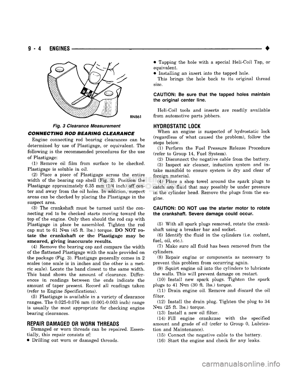
Fig. 3 Clearance Measurement
CONNECTING ROD BEARING CLEARANCE Engine connecting rod bearing clearances can be
determined by use of Plastigage, or equivalent. The
following is the recommended procedures for the use of Plastigage:
(1) Remove oil film from surface to be checked.
Plastigage is soluble in oil.
(2) Place a piece of Plastigage across the entire
width of the bearing cap shell (Fig. 2). Position the
Plastigage approximately 6.35 mm (1/4 inch) off cen
ter and away from the oil holes. In addition, suspect areas can be checked by placing the Plastigage in the
suspect area. (3) The crankshaft must be turned until the con
necting rod to be checked starts moving toward the
top of the engine. Only then should the rod cap with
Plastigage in place be assembled. Tighten the rod
cap nut to 61 Nnn (45 ft. lbs.) torque. DO NOT ro
tate the crankshaft or the Plastigage may be smeared, giving inaccurate results. (4) Remove the bearing cap and compare the width
of the flattened Plastigage with the scale provided on
the package (Fig. 3). Plastigage generally comes in 2 scales (one scale is in inches and the other is a met
ric scale). Locate the band closest to the same width.
This band shows the amount of clearance. Differ ences in readings between the ends indicate the
amount of taper present. Record all readings taken (refer to Engine Specifications). (5) Plastigage is available in a variety of clearance
ranges. The 0.025-0.076 mm (0.001-0.003 inch) range
is usually the most appropriate for checking engine
bearing clearances.
REPAIR DAMAGED OR WORN THREADS Damaged or worn threads can be repaired. Essen
tially, this repair consists of:
• Drilling out worn or damaged threads. • Tapping the hole with a special Heli-Coil Tap, or
equivalent.
• Installing an insert into the tapped hole.
This brings the hole back to its original thread
size.
CAUTION:
Be
sure
that
the tapped holes maintain
the original
center
line.
Heli-Coil tools and inserts are readily available
from automotive parts jobbers.
HYDROSTATIC
LOCK
When an engine is suspected of hydrostatic lock
(regardless of what caused the problem), follow the
steps below. (1) Perform the Fuel Pressure Release Procedure
(refer to Group 14, Fuel System). (2) Disconnect the negative cable from the battery.
(3) Inspect air cleaner, induction system and in
take manifold to ensure system is dry and clear of
foreign material. (4) Place a shop towel around the spark plugs to
catch any fluid that may possibly be under pressure
in the cylinder head. Remove the plugs from the en
gine.
CAUTION:
DO NOT use the starter motor to
rotate
the
crankshaft.
Severe
damage
could
occur.
(5) With all spark plugs removed, rotate the crank
shaft using a breaker bar and socket.
(6) Identify the fluid in the cylinders (i.e. coolant,
fuel, oil, etc.).
(7) Make sure all fluid has been removed from the
cylinders. (8) Repair engine or components as necessary to
prevent this problem from occurring again.
(9) Squirt engine oil into the cylinders to lubricate
the walls. This will prevent damage on restart.
(10) Install new spark plugs. Tighten the spark
plugs to 41 N#m (30 ft. lbs.) torque. (11) Drain engine oil. Remove and discard the oil
filter.
(12) Install the drain plug. Tighten the plug to 34
N-m (25 ft. lbs.) torque.
(13) Install a new oil filter.
(14) Fill engine crankcase with the specified
amount and grade of oil (refer to Group 0, Lubrica
tion and Maintenance). (15) Connect the negative cable to the battery.
(16) Start the engine and check for any leaks.
Page 611 of 1502

9
- 6
ENGINES
•
SERVICE DIAGNOSIS (GASOLINE ENGINES)
•
PERFORMANCE (CONT.)
1
CONDITION
POSSIBLE
CAUSES
^
CORRECTION
1
ENGINE
LOSS
OF
POWER
1.
Incorrect ignition timing.
2. Worn or burned distributor
rotor.
3. Worn distributor shaft.
4.
Dirty
or
incorrectly
gapped
spark
plugs.
5.
Dirt
or
water
in
fuel
system.
6.
Faulty
fuel
pump.
7.
Incorrect valve timing.
8.
Blown
cylinder head
gasket.
9.
Low
compression.
10.
Burned,
warped or
pitted
valves.
11.
Plugged
or
restricted
exhaust
system.
12. Faulty ignition
cables.
13. Faulty coil.
1.
Refer
to
Group
8D, Ignition
System.
2. install new distributor
rotor.
3.
Remove
and
repair
distributor
(refer
to
Group
8D, Ignition
System).
4.
Clean
plugs
and
set gap
(refer
to
Group
8D, Ignition
System).
5. Clean
system
and replace
fuel
filter.
6. Install new
fuel
pump.
7.
Correct
valve
timing.
8. Install new cylinder head
gasket.
9.
Test
compression
of
each
cylinder.
10.
Install new
valves.
11.
Install new
parts,
as
necessary.
12.
Replace
any cracked or
shorted
cables.
13.
Test
and
replace,
as
necessary
(refer
to
Group
8D, Ignition
System).
ENGINE
MISSES
ON
ACCELERATION
1.
Dirty
or
gap set
too
wide
in spark
plug.
2. Incorrect ignition timing.
3.
Dirt
in
fuel
system.
4.
Burned,
warped or
pitted
valves.
5. Faulty coil.
1.
Clean spark
plugs
and set gap
(refer
to
Group
8D, Ignition
System).
2. Refer to
Group
8D, Ignition
System.
3. Clean
fuel
system.
4.
Install new
valves.
5.
Test
and
replace,
if
necessary,
(refer
to
Group
8D, Ignition
System).
ENGINE
MISSES
AT HIGH
SPEED
1.
Dirty
or
gap set too
wide
in spark
plug.
2. Worn distributor shaft.
3. Worn or burned distributor
rotor.
4. Faulty
coil.
5. Incorrect ignition timing.
6.
Dirty
injector
in
throttle
body.
7.
Dirt
or
water
in
fuel
system.
1.
Clean
spark
plugs
and
set gap
(refer
to
Group
8D, Ignition
System).
2.
Remove
and
repair
distributor
(refer
to
Group
8D,
Ignition
System).
3. Install new distributor
rotor.
4.
Test
and replace,
as
necessary
(refer
to
Group
8D, Ignition
System).
5.
Refer
to
Group
8D, Ignition
System.
6.
Clean
injector.
7.
Clean
system
and replace
fuel
filter.
J9309-106