1993 DODGE TRUCK air filter
[x] Cancel search: air filterPage 1203 of 1502
21
- 202
TRANSMISSION
OVERHAUL—36RH/37RH
•
Fig.
44
Removing
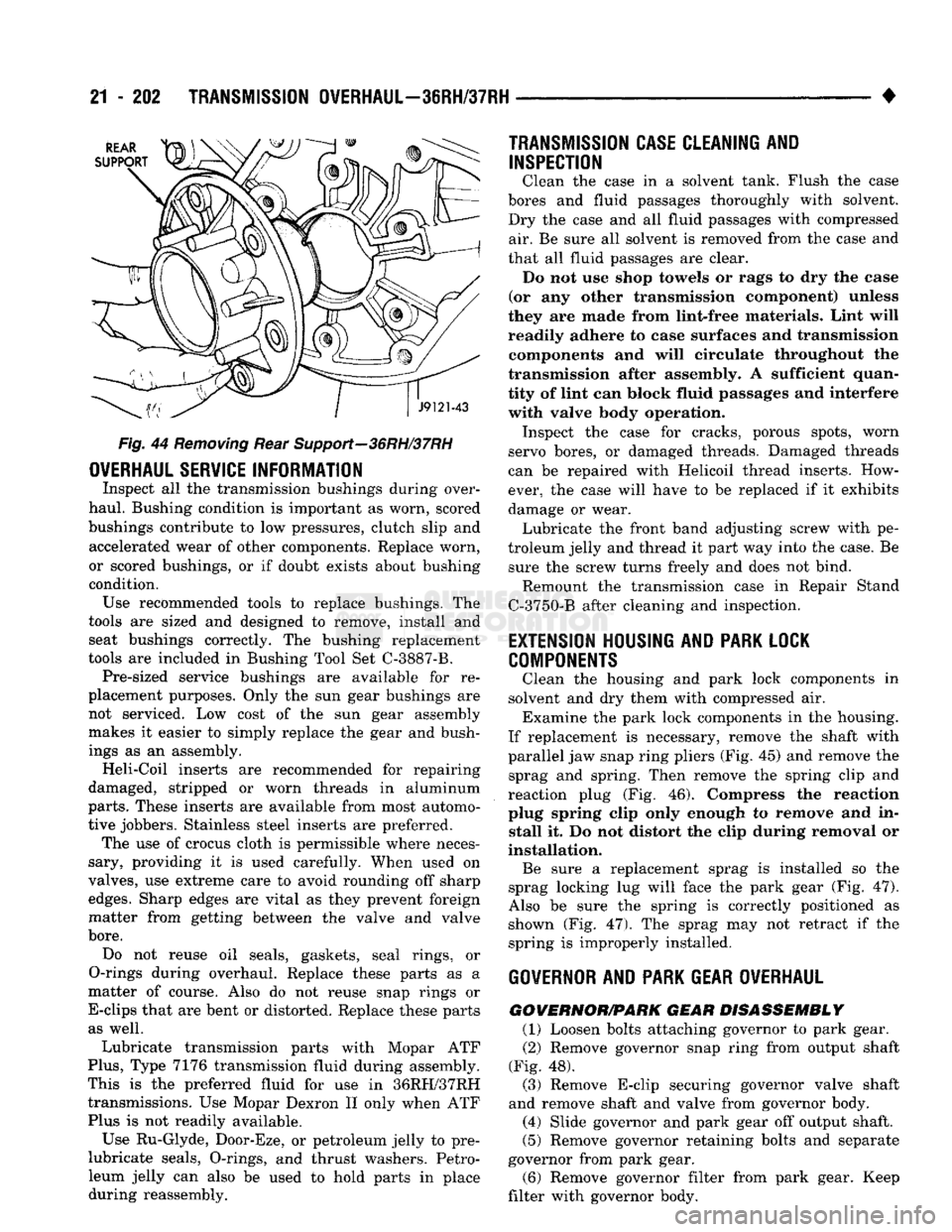
Rear Support—36RH/37RH
OVERHAUL
SERVICE
INFORMATION
Inspect
all the
transmission bushings during over
haul. Bushing condition
is
important
as
worn, scored
bushings contribute
to low
pressures, clutch slip
and
accelerated wear
of
other components. Replace worn,
or scored bushings,
or if
doubt exists about bushing
condition. Use recommended tools
to
replace bushings.
The
tools
are
sized
and
designed
to
remove, install
and
seat bushings correctly.
The
bushing replacement
tools
are
included
in
Bushing Tool
Set
C-3887-B. Pre-sized service bushings
are
available
for re
placement purposes. Only
the sun
gear bushings
are
not serviced.
Low
cost
of the sun
gear assembly
makes
it
easier
to
simply replace
the
gear
and
bush
ings
as an
assembly. Heli-Coil inserts
are
recommended
for
repairing
damaged, stripped
or
worn threads
in
aluminum
parts.
These inserts
are
available from most automo
tive jobbers. Stainless steel inserts
are
preferred. The
use of
crocus cloth
is
permissible where neces
sary, providing
it is
used carefully. When used
on
valves,
use
extreme care
to
avoid rounding
off
sharp
edges.
Sharp edges
are
vital
as
they prevent foreign
matter from getting between
the
valve
and
valve
bore.
Do
not
reuse
oil
seals, gaskets, seal rings,
or
O-rings during overhaul. Replace these parts
as a
matter
of
course. Also
do not
reuse snap rings
or
E-clips that
are
bent
or
distorted. Replace these parts as well.
Lubricate transmission parts with Mopar
ATF
Plus,
Type
7176
transmission fluid during assembly.
This
is the
preferred fluid
for use in
36RH/37RH transmissions.
Use
Mopar Dexron
II
only when
ATF
Plus
is not
readily available.
Use Ru-Glyde, Door-Eze,
or
petroleum jelly
to pre-
lubricate seals, O-rings,
and
thrust washers. Petro
leum jelly
can
also
be
used
to
hold parts
in
place during reassembly.
TRANSMISSION CASE
CLEAN1NI
AND
INSPECTION
Clean
the
case
in a
solvent tank. Flush
the
case
bores
and
fluid passages thoroughly with solvent.
Dry
the
case
and all
fluid passages with compressed air.
Be
sure
all
solvent
is
removed from
the
case
and
that
all
fluid passages
are
clear. Do
not use
shop towels
or
rags
to dry the
ease
(or
any
other transmission component) unless
they
are
made from lint-free materials. Lint will
readily adhere
to
case surfaces
and
transmission components
and
will circulate throughout
the
transmission after assembly.
A
sufficient quan
tity
of
lint
can
block fluid passages
and
interfere with valve body operation. Inspect
the
case
for
cracks, porous spots, worn
servo bores,
or
damaged threads. Damaged threads
can
be
repaired with Helicoil thread inserts. How
ever,
the
case will have
to be
replaced
if it
exhibits
damage
or
wear. Lubricate
the
front band adjusting screw with
pe
troleum jelly
and
thread
it
part
way
into
the
case.
Be
sure
the
screw turns freely
and
does
not
bind. Remount
the
transmission case
in
Repair Stand
C-3750-B after cleaning
and
inspection.
EXTENSION
HOUSING
AND PARK
LOCK
COMPONENTS
Clean
the
housing
and
park lock components
in
solvent
and dry
them with compressed
air.
Examine
the
park lock components
in the
housing.
If replacement
is
necessary, remove
the
shaft with
parallel
jaw
snap ring pliers
(Fig. 45) and
remove
the
sprag
and
spring. Then remove
the
spring clip
and
reaction plug
(Fig. 46).
Compress
the
reaction
plug spring clip only enough
to
remove
and in
stall
it. Do not
distort
the
clip during removal
or
installation. Be sure
a
replacement sprag
is
installed
so the
sprag locking
lug
will face
the
park gear
(Fig. 47).
Also
be
sure
the
spring
is
correctly positioned
as
shown
(Fig. 47). The
sprag
may not
retract
if the
spring
is
improperly installed.
GOVERNOR
AND PARK
GEAR OVERHAUL
GOWERNOR/PARK
GEAR DISASSEMBLY
(1) Loosen bolts attaching governor
to
park gear.
(2) Remove governor snap ring from output shaft
(Fig.
48).
(3) Remove E-clip securing governor valve shaft
and remove shaft
and
valve from governor body. (4) Slide governor
and
park gear
off
output shaft.
(5) Remove governor retaining bolts
and
separate
governor from park gear.
(6) Remove governor filter from park gear. Keep
filter with governor body.
Page 1205 of 1502
21 - 204
TRANSMISSION OVERHAUL—36RH/37RH
• loyed
brass.
The third change involves the
36RH/37RH
output
shaft
which
has been spot-
faced for governor valve end clearance. The new
aluminum
valve must only be used with an
out
put
shaft that
has a spotface. The alloyed gover
nor weight
must
only be
used
In 37RH diesel
transmissions. In addition, the governor body and spotfaced side of the output shaft must be
indexed during assembly.
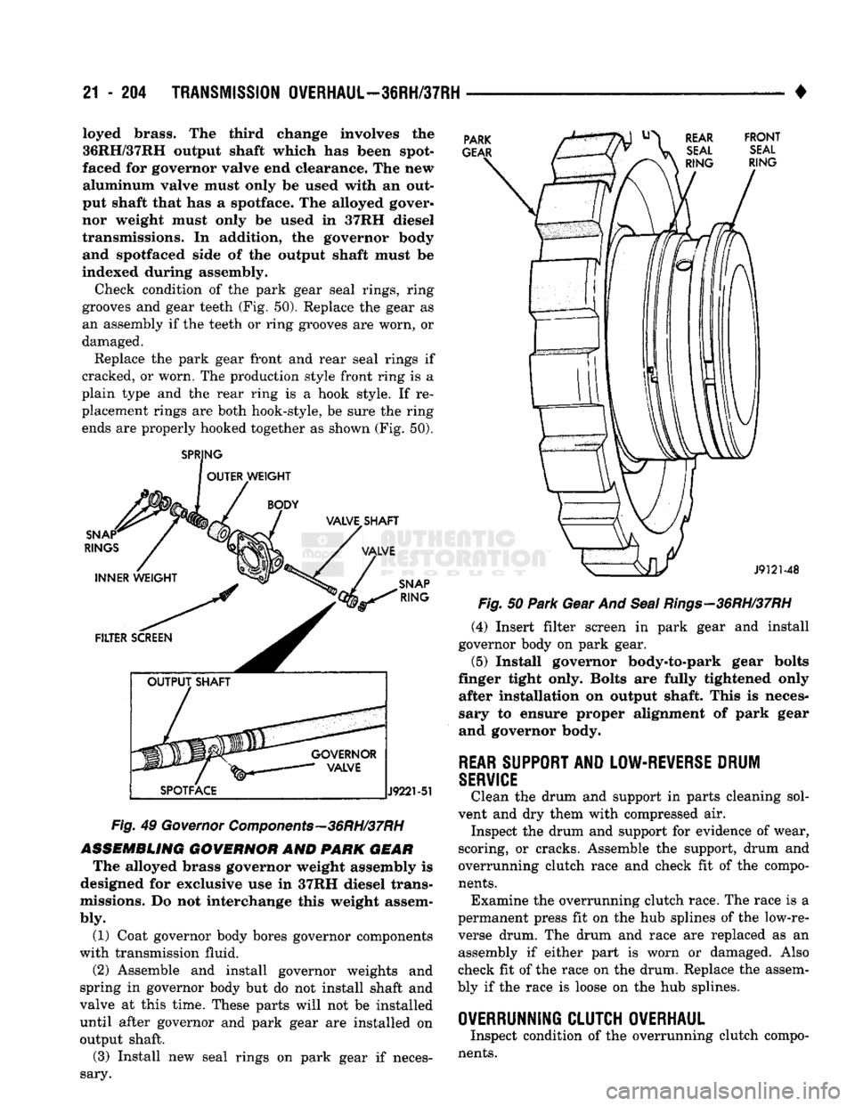
Check condition of the park gear seal rings, ring
grooves and gear teeth (Fig. 50). Replace the gear as
an assembly if the teeth or ring grooves are worn, or damaged.
Replace the park gear front and rear seal rings if
cracked, or worn. The production style front ring is a
plain type and the rear ring is a hook style. If re
placement rings are both hook-style, be sure the ring ends are properly hooked together as shown (Fig. 50).
SPRJNG
OUTER WEIGHT PARK
GEAR REAR FRONT
SEAL SEAL
RING
RING SNAP*
RINGS
INNER WEIGHT VALVET SHAFT
VALVE
SNAP
RING
FILTER SCREEN
GOVERNOR VALVE
SPOTFACE
J9221-51
Fig.
49
Governor
Components—36RH/37RH
ASSEMBLING
GOVERNOR
AND PARK
GEAR
The alloyed brass governor weight assembly is
designed for exclusive use in 37RH diesel trans
missions. Do not interchange this weight assem
bly.
(1) Coat governor body bores governor components
with transmission fluid.
(2) Assemble and install governor weights and
spring in governor body but do not install shaft and
valve at this time. These parts will not be installed until after governor and park gear are installed on output shaft.
(3) Install new seal rings on park gear if neces
sary.
J9121-48
Fig.
50
Park
Gear And
Seal
Rings—36RH/37RH
(4) Insert filter screen in park gear and install
governor body on park gear.
(5)
Install governor body-to-park gear bolts
finger tight only. Bolts are fully tightened only after installation on output shaft. This is neces
sary to ensure proper alignment of park gear
and governor body.
REAR
SUPPORT
AND
LOW-REVERSE
DRUM
SERVICE
Clean the drum and support in parts cleaning sol
vent and dry them with compressed air. Inspect the drum and support for evidence of wear,
scoring, or cracks. Assemble the support, drum and
overrunning clutch race and check fit of the compo
nents.
Examine the overrunning clutch race. The race is a
permanent press fit on the hub splines of the low-re
verse drum. The drum and race are replaced as an assembly if either part is worn or damaged. Also
check fit of the race on the drum. Replace the assem
bly if the race is loose on the hub splines.
OVERRUNNING CLUTCH OVERHAUL
Inspect condition of the overrunning clutch compo
nents.
Page 1221 of 1502
21
- 220
TRANSMISSION OVERHAUL—36RH/37RH
•
VALVE
BODY CLEANING AND INSPECTION
The only serviceable valve body components are
the:
• park lock rod and E-clip
• switch valve and spring
• pressure adjusting screw bracket
• throttle valve lever
• manual shaft
• manual shaft seal/washer/E-clip/detent ball
• fluid filter.
The remaining valve body components are serviced
only as part of a complete valve body assembly (Fig.
92).
Clean the valve body components in a parts clean
ing solution only. Do not use gasoline, kerosene, or
any type of caustic solution.
Dry the parts with compressed air. Make sure all
passages are clean and free from obstructions. Do not use rags or shop towels to dry or wipe
off valve body components unless they are made
from lint free material. Lint will adhere to the
valve body components causing valve bind. Lint
can also clog filters and small fluid passages.
Inspect the throttle and manual valve levers and
shafts.
Do not attempt to straighten a bent shaft
or correct a loose lever. Replace these compo
nents if worn, bent, loose or damaged in any way.
Inspect all of the valve body mating surfaces for
scratches, nicks, burrs, or distortion. Use a straight
edge to check surface flatness. Minor scratches may
be removed with crocus cloth using only very light pressure.
Minor distortion of a valve body mating surface
may be corrected by smoothing the surface with cro
cus cloth. Position the crocus cloth sheet on a surface
plate, sheet of plate glass, or equally flat surface. If distortion is severe or any surfaces are heavily
scored, the valve body will have to be replaced.
CAUTION:
The
throttle
valve, shuttle valve plug,
1-2
shift valve
and 1-2
governor plug
are
made
of
coated aluminum. Aluminum components
can be
identified
by the
dark color
of the
special coating
applied
to the
surface
(or by
testing
with
a
magnet).
DO
NOT
polish
or
sand
aluminum valves
or
plugs
with
any
type
of
material,
or
under
any
circum
stances.
This practice
will
remove
the
special coat
ing
and
cause
the
valves
and
plugs
to
stick
and
bind.
Inspect the valves and plugs for scratches, burrs,
nicks,
or scores. Also inspect the coating on the alu
minum valves and plugs. If the coating is damaged
or worn through, the valve (or valve body) should be
replaced.
Aluminum valves and plugs must not be sanded or
polished under any circumstances. However, minor burrs or scratches on steel valves and plugs can be
removed with crocus cloth but do not round off the
valve or plug edges. Squareness of these edges is vi
tally important; they prevent foreign matter from lodging between the valves and plugs and the bore.
Inspect all the valve and plug bores in the valve
body. Use a penlight to view the bore interiors. Re
place the valve body if any bores are distorted or scored. Inspect all of the valve body springs. The
springs must be free of distortion, warpage or broken
coils.
Trial fit each valve and plug in its bore to check
freedom of operation. When clean and dry, the valves and plugs should drop freely into the bores.
Valve body bores do not change dimensionally with
use.
If the valve body functioned correctly when new,
it will continue to operate properly after cleaning and inspection. It should not be necessary to replace a valve body assembly unless it is damaged in han
dling.
VALVE BODY ASSEMBLY
CAUTION:
Do not
force
the
valves
or
plugs
into place during reassembly.
If the
valve body bores
and
the
valves
and
plugs
are
free
of
distortion
or
burrs,
the
valves
and
plugs
should slide into place
easily.
In
addition,
do not
overtighten
the
transfer plate
and
valve body screws during reassembly.
Overtightening
can
distort
the
valve body resulting
in valve sticking,
cross
leakage
and
unsatisfactory
operation. Tighten
the
screws
alternately
and
evenly
to 4 Nnn (35 in.
lbs.) torque only.
(1) Lubricate valve body bores, valves and plugs
with ATF Plus, or Dexron II™ transmission fluid.
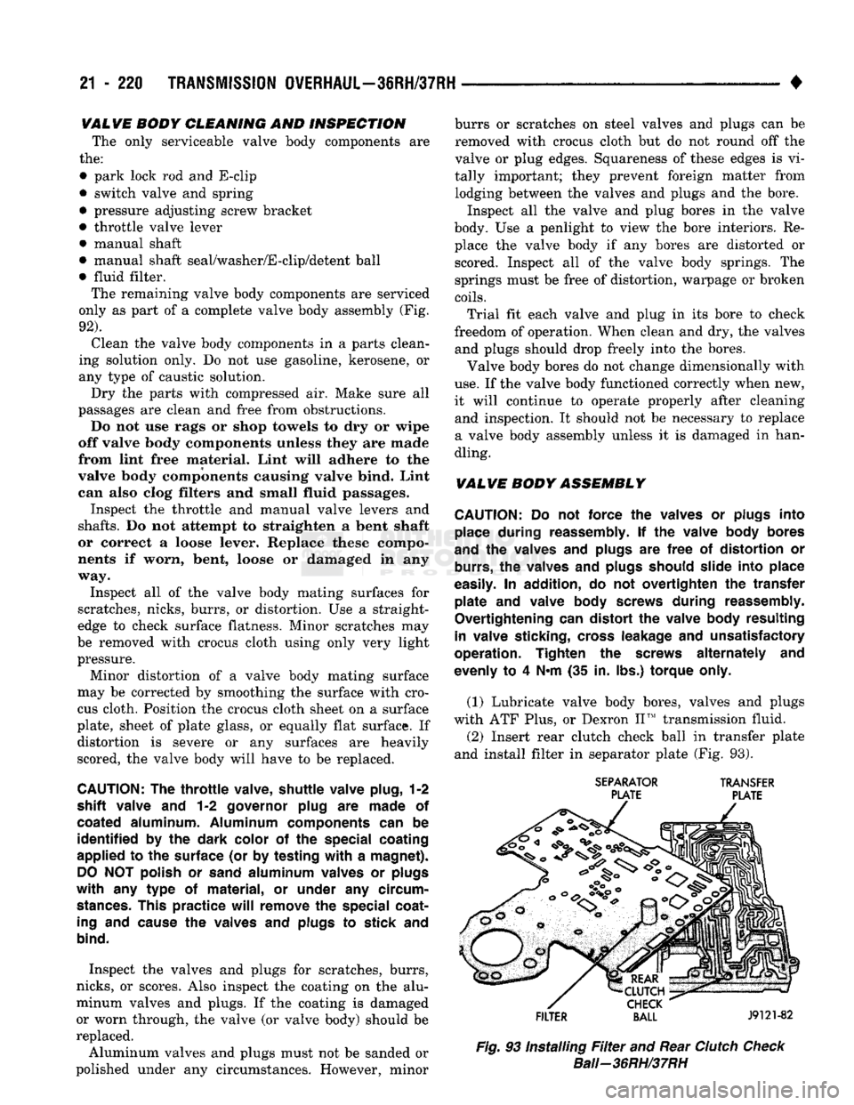
(2) Insert rear clutch check ball in transfer plate
and install filter in separator plate (Fig. 93).
SEPARATOR
TRANSFER
PLATE PLATE
FILTER
BALL
J9121-82
Fig.
93 Installing
Filter
and Rear
Clutch
Check
Bali—36RH/37RH
Page 1235 of 1502
21
- 234
TRANSMISSION
0VERHAUL-42RH
J9321-133
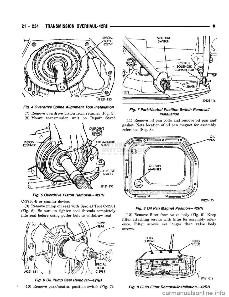
Fig.
4 Overdrive
Spline
Alignment
Tool
Installation
(7) Remove overdrive piston from retainer (Fig. 5).
(8) Mount transmission unit on Repair Stand
Fig.
5 Overdrive
Piston
Removal—42RH C-3750-B or similar device.
(9) Remove pump oil seal with Special Tool C-3981
(Fig. 6). Be sure to tighten tool threads completely
into seal before using puller bolt to withdraw seal.
Fig.
6 Oil
Pump
Seal
Removal—42RH
I
(10) Remove park/neutral position switch (Fig. 7). •
Fig.
7 Park/Neutral Position
Switch
Removal/
Installation
(11) Remove oil pan bolts and remove oil pan and
gasket. Note location of oil pan magnet for assembly reference (Fig. 8).
J9121-115
Fig.
8 Oil Pan Magnet Position—42RH (12) Remove filter from valve body (Fig. 9). Keep
filter attaching screws with filter for assembly refer
ence.
Filter screws are longer than valve body screws.
Fig.
9 Fluid
Filter
Removal/Installation—42RH
Page 1264 of 1502
4
TRANSMISSION
QVERHAUL-42RH
21 - 263
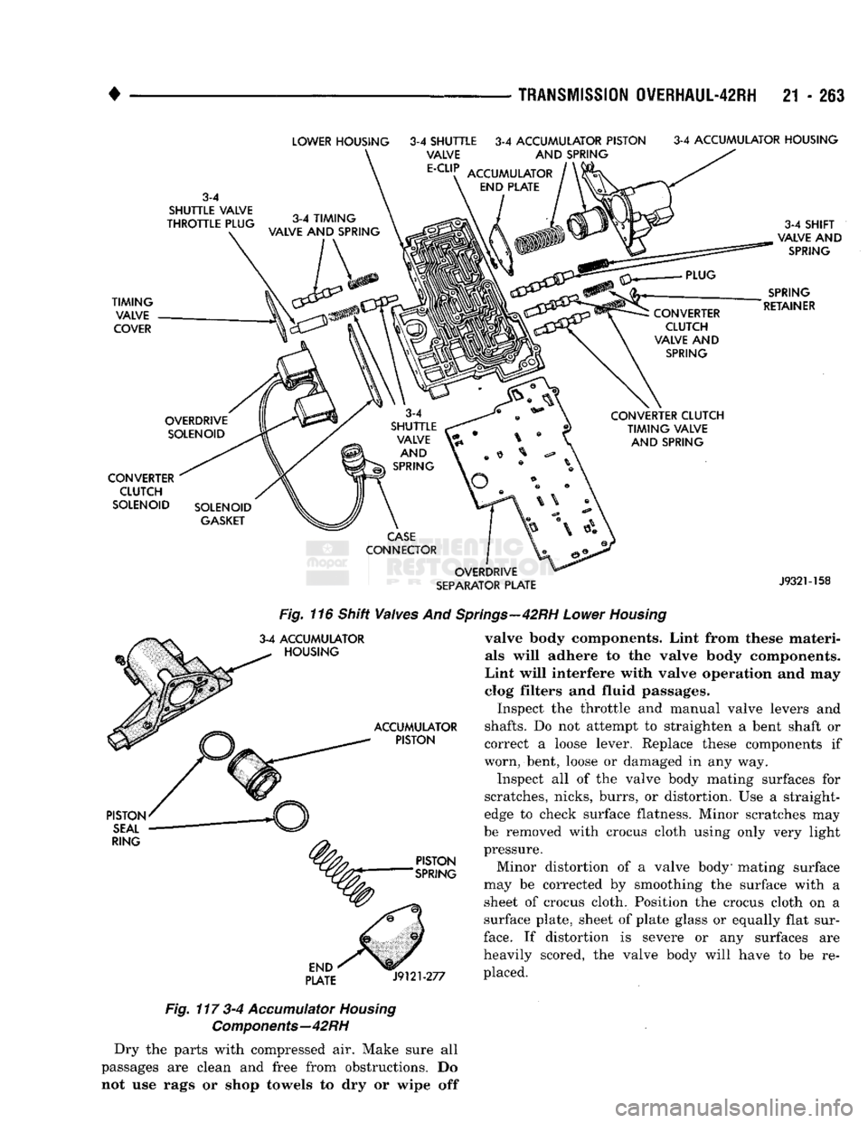
Fig.
116 Shift Valves And 3-4 ACCUMULATOR
^ HOUSING
PLATE
J9121-277
Fig.
117 3-4
Accumulator
Housing
Components—42
RH
Dry the parts with compressed air. Make sure all
passages are clean and free from obstructions. Do not use rags or shop towels to dry or wipe off
wings—42RH
Lower
Housing
valve body components. Lint from these materials will adhere to the valve body components.
Lint will interfere with valve operation and may
clog filters and fluid passages.
Inspect the throttle and manual valve levers and
shafts.
Do not attempt to straighten a bent shaft or
correct a loose lever. Replace these components if
worn, bent, loose or damaged in any way.
Inspect all of the valve body mating surfaces for
scratches, nicks, burrs, or distortion. Use a straight
edge to check surface flatness. Minor scratches may
be removed with crocus cloth using only very light
pressure.
Minor distortion of a valve body' mating surface
may be corrected by smoothing the surface with a sheet of crocus cloth. Position the crocus cloth on a
surface plate, sheet of plate glass or equally flat sur
face.
If distortion is severe or any surfaces are
heavily scored, the valve body will have to be re
placed.
Page 1309 of 1502
21 - 308
TRANSMISSION OVERHAUL-46RH
•
UPPER
HOUSING
PLUG RETAINER
AND
VALVE
COVER SPRING COVER
J9321-157
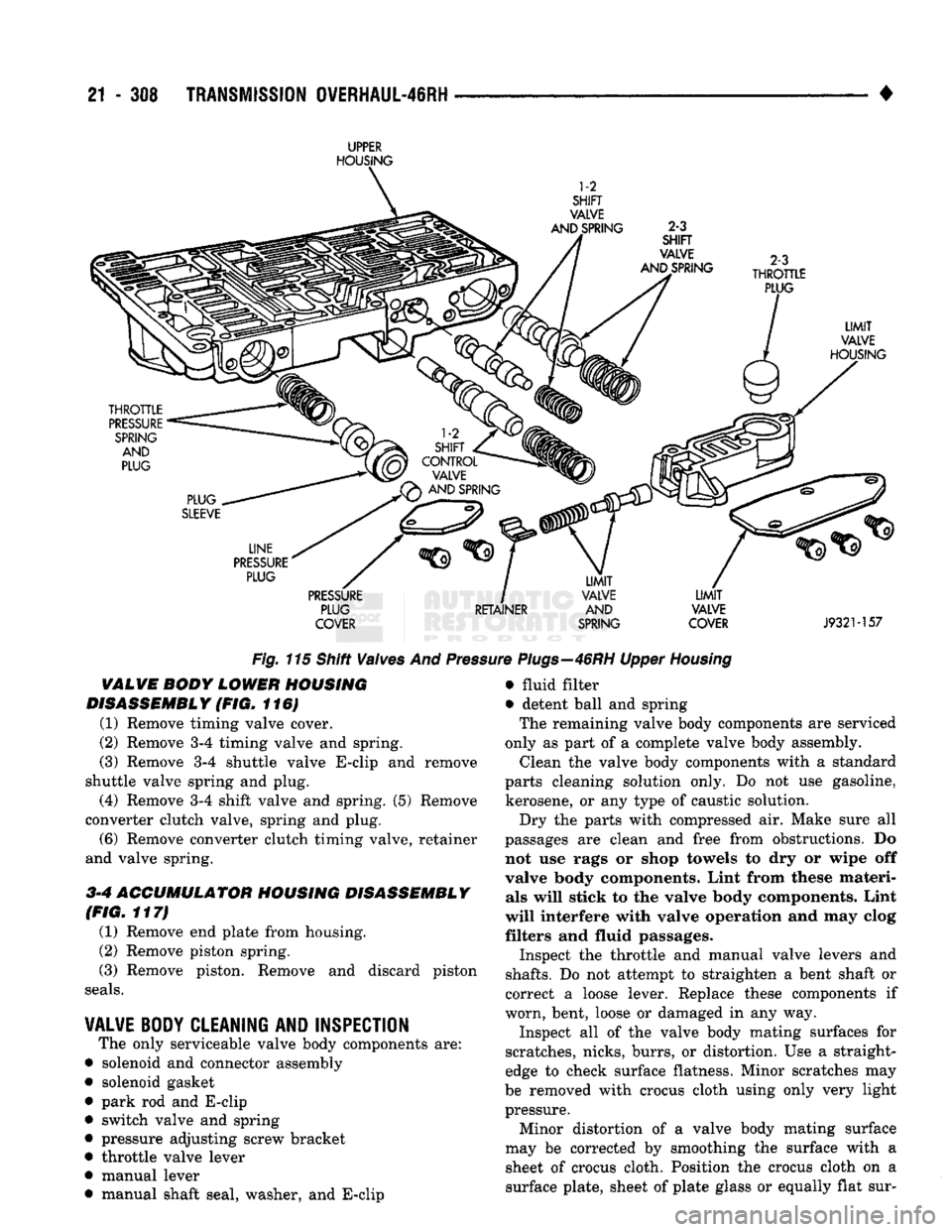
Fig.
115 Shift Valves And
Pres
VALVE
BODY
LOWER
HOUSING
DISASSEMBLY
(FIG. 116)
(1) Remove timing valve cover.
(2) Remove 3-4 timing valve and spring.
(3) Remove 3-4 shuttle valve E-clip and remove
shuttle valve spring and plug.
(4) Remove 3-4 shift valve and spring. (5) Remove
converter clutch valve, spring and plug. (6) Remove converter clutch timing valve, retainer
and valve spring.
3-4
ACCUMULATOR HOUSING DISASSEMBLY
(FIG.
117)
(1) Remove end plate from housing.
(2) Remove piston spring. (3) Remove piston. Remove and discard piston
seals.
VALVE BODY CLEANING
AND
INSPECTION
The only serviceable valve body components are:
• solenoid and connector assembly
• solenoid gasket
• park rod and E-clip
• switch valve and spring
• pressure adjusting screw bracket
• throttle valve lever • manual lever
• manual shaft seal, washer, and E-clip e
Plugs—46RH
Upper
Housing
• fluid filter
• detent ball and spring The remaining valve body components are serviced
only as part of a complete valve body assembly. Clean the valve body components with a standard
parts cleaning solution only. Do not use gasoline,
kerosene, or any type of caustic solution.
Dry the parts with compressed air. Make sure all
passages are clean and free from obstructions. Do
not use rags or shop towels to dry or wipe off
valve body components. Lint from these materi als will stick to the valve body components. Lint
will interfere with valve operation and may clog
filters and fluid passages.
Inspect the throttle and manual valve levers and
shafts.
Do not attempt to straighten a bent shaft or
correct a loose lever. Replace these components if
worn, bent, loose or damaged in any way.
Inspect all of the valve body mating surfaces for
scratches, nicks, burrs, or distortion. Use a straight
edge to check surface flatness. Minor scratches may
be removed with crocus cloth using only very light pressure.
Minor distortion of a valve body mating surface
may be corrected by smoothing the surface with a sheet of crocus cloth. Position the crocus cloth on a
surface plate, sheet of plate glass or equally flat sur-
Page 1331 of 1502
21
- 330
OVERDRIVE
UNIT
OVERHAUL—42RH/46RH
•
DIRECT
CLUTCH
DRUM
PUNCH
8921-249
OUTER
RETAINING
RING
J9121-293
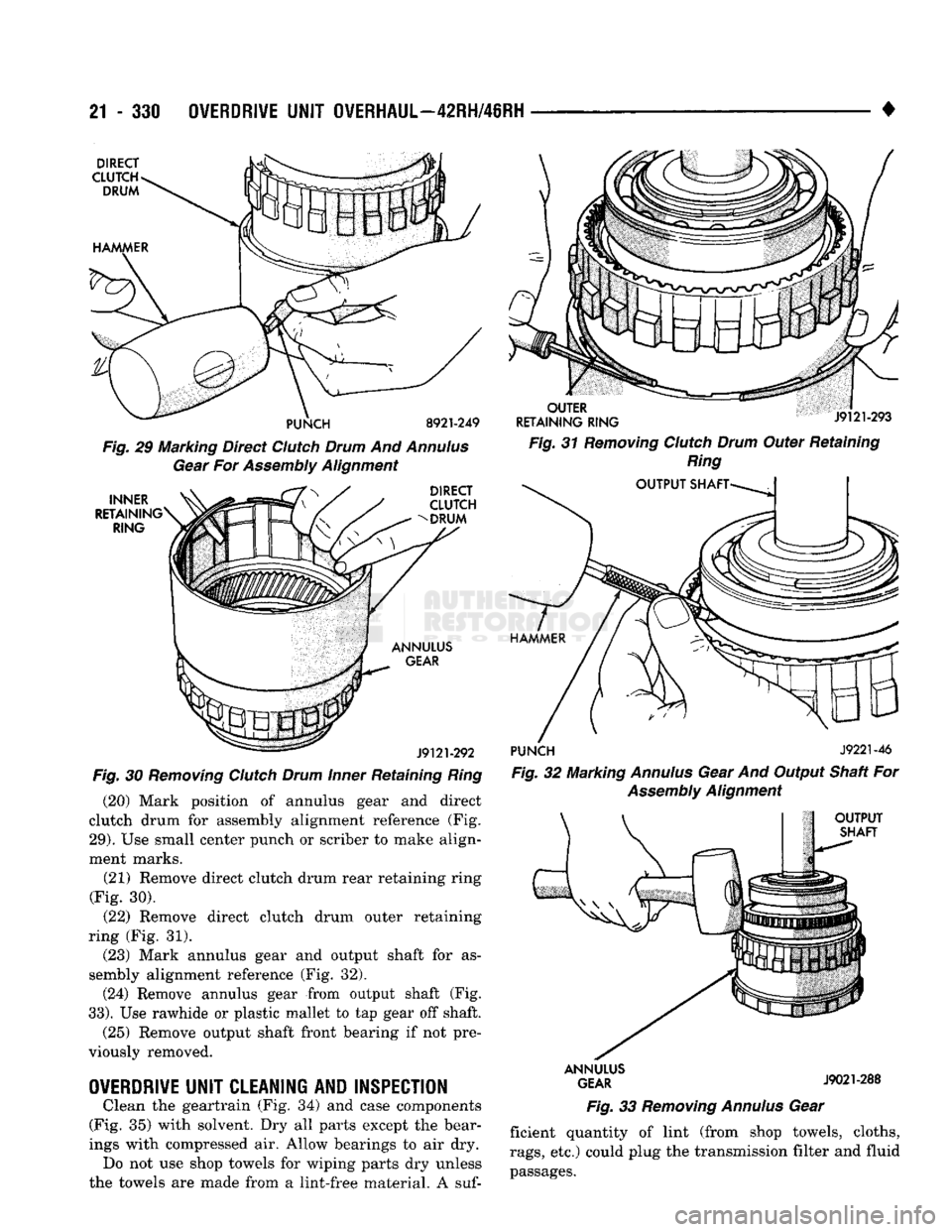
Fig.
29 Marking Direct
Clutch
Drum
And
Annulus
Gear
For
Assembly
Alignment
INNER
RETAINING
RING DIRECT
CLUTCH
DRUM
Fig.
31
Removing
Clutch
Drum
Outer Retaining
Ring
OUTPUT
SHAFT-
ANNULUS
GEAR
J9121-292
Fig.
30
Removing
Clutch
Drum
Inner
Retaining
Ring
(20) Mark position of annulus gear and direct
clutch drum for assembly alignment reference (Fig.
29).
Use small center punch or scriber to make align
ment marks.
(21) Remove direct clutch drum rear retaining ring
(Fig. 30).
(22) Remove direct clutch drum outer retaining
ring (Fig. 31).
(23) Mark annulus gear and output shaft for as
sembly alignment reference (Fig. 32). (24) Remove annulus gear from output shaft (Fig.
33).
Use rawhide or plastic mallet to tap gear off shaft.
(25) Remove output shaft front bearing if not pre
viously removed.
OVERDRIVE
UNIT
CLEANING
AND
INSPECTION
Clean the geartrain (Fig. 34) and case components
(Fig. 35) with solvent. Dry all parts except the bear
ings with compressed air. Allow bearings to air dry. Do not use shop towels for wiping parts dry unless
the towels are made from a lint-free material. A suf-
PUNCH
J9221-46
Fig.
32 Marking
Annulus
Gear And Output Shaft For
Assembly
Alignment
OUTPUT
SHAFT
ANNULUS
GEAR
J9021-288
Fig.
33
Removing
Annulus
Gear ficient quantity of lint (from shop towels, cloths,
rags,
etc.) could plug the transmission filter and fluid
passages.
Page 1438 of 1502
•
• —• •
HEATING
AND AIR
CONDITIONING
24 - 1 CONTENTS
page
CLIMATE CONTROL SYSTEM
............. 21
REFRIGERANT SYSTEM SERWICE
COMPRESSOR
SERWICE
(SD-709)
......... 21
PROCEDURES
.............
DIAGNOSTIC PROCEDURES
3
TORQUE SPECIFICATIONS
GENERAL INFORMATION
1
page
. 17
. 31
GENERAL INFORMATION
HEATER SYSTEM
All models use a Blend-Air type heater. Outside air
enters the heater through the cowl opening and
passes through a plenum chamber to the heater core. Air intake openings must be kept free of snow, ice and other obstructions for the heater system to pick
up sufficient outside air. A temperature control door
in the heater housing directs incoming air through
the heater core and/or the heater core bypass. The amount of blend (heated and non-heated air) is deter
mined by the setting of the temperature lever on the
instrument panel. Direction of the blended air is con
trolled by the HEAT-DEFROST lever on the instru ment panel. The blower switch and resistor block controls the
speed of the blower motor. This in turn controls the
velocity of the air flow from the heater outlets. The resistor block consists of 2 helical wound wire
resistors connected to terminals which are mechani cally attached to a glass-filled phenolic board. This
assembly is bolted to the plenum. The blower switch controls the blower motor speed
by selectively connecting the resistors in series to the
blower motor.
A self-adjusting clip, on each of 2 control cables has
been incorporated to simplify cable adjustment. This clip snaps onto the control cable core wire and will slide along the wire under a specific load to provide
an automatic cable adjustment.
AIR
CONDITIONING
SYSTEM
Air intake openings must be kept free of snow, ice
and other obstructions for the air conditioning sys
tem to pick up sufficient outside air.
COMPONENTS
• COMPRESSOR-The seven piston SD-709 com
pressor is used on all vehicles. This compressor com
presses the low pressure refrigerant vapor into a high pressure, high temperature vapor. • CLUTCH PULLEY AND COIL-These are
mounted on the compressor, providing a convenient
way to drive it and disengage it in accordance to the cooling needs.
• CONDENSER-The condenser is located in front
of the radiator. Its function is to cool the hot, high
pressure refrigerant gas causing it to condense into
high pressure liquid refrigerant.
• FILTER-DRIER—The filter-drier is used to remove
any traces of moisture from the refrigerant system.
This component incorporates the sight glass and the
high pressure relief valve.
• SIGHT GLASS-The sight glass is provided as a
diagnostic tool to observe refrigerant flow and indi cate refrigerant level. It is located at the top of the
filter drier.
• HIGH -PRESSURE RELIEF VALVE-This is a safety device designed to open automatically if the
system pressure reaches a predetermined level. This
will prevent system component damage. • EXPANSION (H) VALVE-The expansion (H)
valve is used to meter refrigerant into the evaporator
in accordance with cooling requirements. • EVAPORATOR COIL-The evaporator coil is lo
cated in the A/C unit. Its function is to cool and de-
humidify the air before it enters the vehicle. • FREEZE CONTROL-The main function of freeze
control is to prevent water on the evaporator coil face
from freezing which restricts the airflow. An elec
tronic temperature cycling switch is located on the
refrigerant plumbing (suction line) near the H-Valve.
The switch turns the compressor ON-OFF depending
on the temperature in the suction line. The switch is a sealed, specially calibrated unit. If found defective,
the switch must be replaced. • REFRIGERANT LINES-These lines are needed
to carry the refrigerant between the various system components.
• CONDENSATE DRAIN TUBE-Condensation
which accumulates on the bottom of the evaporator
HEATING
AND AIR
CONDITIONING