1993 DODGE TRUCK air filter
[x] Cancel search: air filterPage 1484 of 1502
•
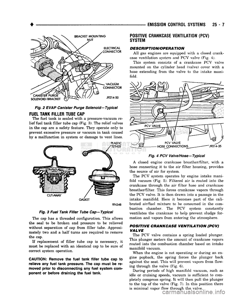
Fig.
2
EVAP
Canister
Purge
Solenoid—Typical
FUEL
TANK
FILLER
TUBE
CAP
The fuel tank is sealed with a pressure-vacuum re
lief fuel tank filler tube cap (Fig. 3). The relief valves
in the cap are a safety feature. They operate only to
prevent excessive pressure or vacuum in tank caused
by a malfunction in system or damage to vent lines.
PLASTIC
GASKET
RN348
Fig.
3
Fuel
Tank
Filler
Tube Cap—Typical
The cap has a threaded configuration. This allows
the seal to be broken and pressure to be relieved without separation of cap from filler tube. Approxi
mately two and a half turns are required to remove
the cap.
If replacement of filler tube cap is necessary, it
must be replaced with an identical cap to be sure of
correct system operation.
CAUTION:
Remove
the
fuel
tank
filler
tube cap to
relieve
any
fuel
tank
pressure.
The cap
must
be re
moved
prior to
disconnecting
any
fuel
system
com
ponent or before draining the
fuel
tank, •—-
EMISSION
CONTROL
SYSTEMS
25 - 7
Fig.
4 PCV Valve/Hose—Typical
A closed engine crankcase breather/filter, with a
hose connecting it to the air filter housing, provides
the source of air for system.
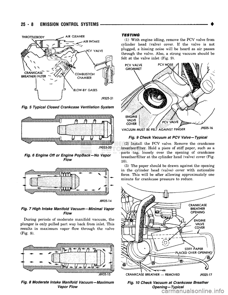
The PCV system operates by engine intake mani
fold vacuum (Fig. 5). Filtered air is routed into the
crankcase through the air filter hose and crankcase
breather/filter. This forces crankcase vapors through
the PCV valve. It is then drawn into a passage in the intake manifold. Here it becomes part of the cali
brated air/fuel mixture to be consumed in the com bustion chamber. The PCV system constantly ventilates the crankcase to help prevent sludge for
mation and vapors from entering the atmosphere.
POSITIVE CRANKCASE VENTILATION (PCV) VALVE The PCV valve contains a spring loaded plunger.
This plunger meters the amount of crankcase vapors
routed into the combustion chamber based on intake
manifold vacuum.
When the engine is not operating or during an en
gine popback, the spring forces the plunger back
against the seat. This will prevent vapors from flow
ing through the valve (Fig. 6).
During periods of high manifold vacuum, such as
idle or cruising speeds, vacuum is sufficient to com
pletely compress spring. It will then pull the plunger
to the top of the valve (Fig. 7). In this position there is minimal vapor flow through the valve.
POSITIVE
CRANKCASE
VENTILATION
(PCV)
SYSTEM
DESCRIPTION/OPERA
TION
All gas engines are equipped with a closed crank
case ventilation system and PCV valve (Fig. 4).
This system consists of a crankcase PCV valve
mounted on the cylinder head (valve) cover with a
hose extending from the valve to the intake mani fold.
Page 1485 of 1502
25 - 8
EMISSION
CONTROL
SYSTEMS
•
Fig.
5 Typical
Closed
Crankcase
Ventilation
System
J9025-20
Fig.
6
Engine
Off or
Engine
PopBack—No
Vapor
Flow
J8925-14
Fig.
7
High
Intake Manifold Vacuum—Minimal Vapor
Flow
During periods of moderate manifold vacuum, the
plunger is only pulled part way back from inlet. This
results in maximum vapor flow through the valve
(Fig. 8).
J8925-15
Fig.
8 Moderate Intake Manifold Vacuum—Maximum Vapor Flow TESTING
(1) With engine idling, remove the PCV valve from
cylinder head (valve) cover. If the valve is not
plugged, a hissing noise will be heard as air passes through the valve. Also, a strong vacuum should be
felt at the valve inlet (Fig. 9).
Fig.
9
Check
Vacuum
at PCV Valve—Typical
(2) Install the PCV valve. Remove the crankcase
breather/filter. Hold a piece of stiff paper, such as a
parts tag, loosely over the opening of crankcase
breather/filter at the cylinder head (valve) cover (Fig.
10).
(3) The paper should be drawn against the opening
in the cylinder head (valve) cover with noticeable
force. This will be after allowing approximately one minute for crankcase pressure to reduce.
CRANKCASE
BREATHER
—
REMOVED
J9325-17
Fig.
10
Check
Vacuum
at
Crankcase
Breather
Opening—Typical
Page 1486 of 1502
•
EMISSION
CONTROL
SYSTEMS
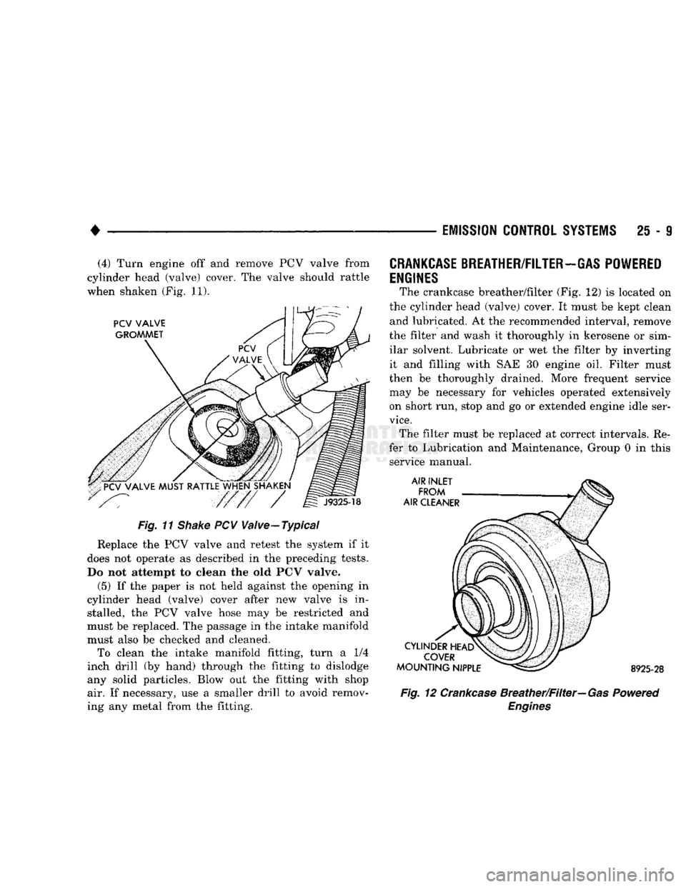
25 - 9 (4) Turn engine off and remove PCV valve from
cylinder head (valve) cover. The valve should rattle
when shaken (Fig. 11).
Fig. 11
Shake
PCV Valve-Typical
Replace the PCV valve and retest the system if it
does not operate as described in the preceding tests.
Do not attempt to clean the old PCV valve.
(5) If the paper is not held against the opening in
cylinder head (valve) cover after new valve is in stalled, the PCV valve hose may be restricted and
must be replaced. The passage in the intake manifold
must also be checked and cleaned. To clean the intake manifold fitting, turn a 1/4
inch drill (by hand) through the fitting to dislodge
any solid particles. Blow out the fitting with shop air. If necessary, use a smaller drill to avoid remov
ing any metal from the fitting.
CRANKCASE
BREATHER/FILTER-GAS POWERED
ENGINES
The crankcase breather/filter (Fig. 12) is located on
the cylinder head (valve) cover. It must be kept clean and lubricated. At the recommended interval, remove
the filter and wash it thoroughly in kerosene or sim ilar solvent. Lubricate or wet the filter by inverting
it and filling with SAE 30 engine oil. Filter must
then be thoroughly drained. More frequent service
may be necessary for vehicles operated extensively on short run, stop and go or extended engine idle ser
vice.
The filter must be replaced at correct intervals. Re
fer to Lubrication and Maintenance, Group 0 in this service manual. 8925-28
Fig. 12 Crankcase Breather/Filter—Gas Powered
Engines
Page 1487 of 1502
25-10
EMISSION
CONTROL
SYSTEMS
EXHAUST
EMISSION
CONTROLS
INDEX
page
Air Inlet—5.9L Diesel
Engine
13
Exhaust
Gas Recirculation (EGR)
Systems
10
HEATED
INLET
AIR
SYSTEM
The air filter housing mounted-heated inlet air sys
tem is no longer used on any Dodge Truck gas pow ered engine.
EXHAUST
GAS
RECIRCULATION
(EGR)
SYSTEMS
GENERAL INFORMATION The EGR system reduces oxides of nitrogen (NOx)
in the engine exhaust and helps prevent spark
knock. This is accomplished by allowing a predeter
mined amount of hot exhaust gas to recirculate and
dilute the incoming fuel/air mixture. This dilution
reduces peak flame temperature during combustion.
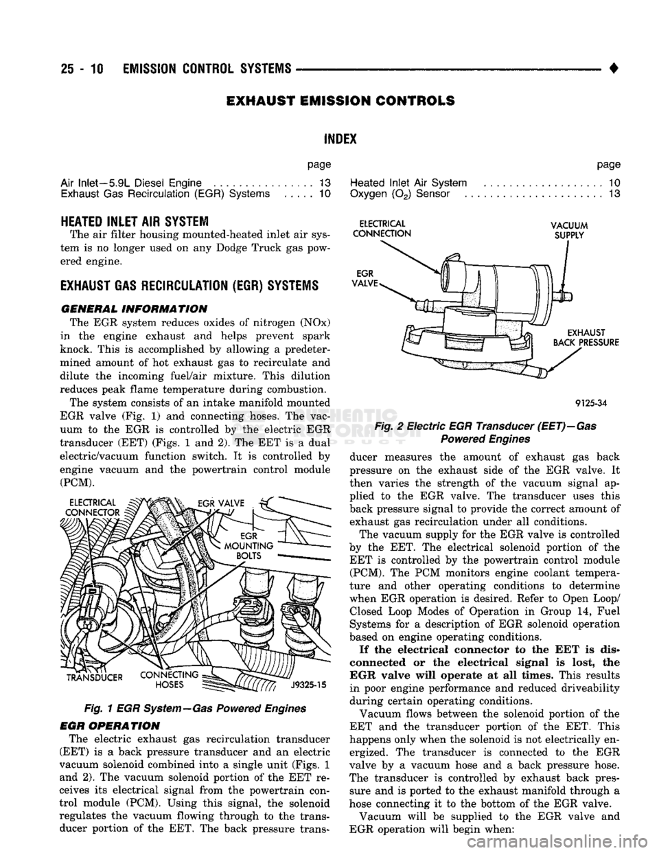
The system consists of an intake manifold mounted
EGR valve (Fig. 1) and connecting hoses. The vac
uum to the EGR is controlled by the electric EGR
transducer (EET) (Figs. 1 and 2). The EET is a dual
electric/vacuum function switch. It is controlled by
engine vacuum and the powertrain control module (PCM).
Fig. 1 EGR System—Gas Powered Engines
EGR OPERATION The electric exhaust gas recirculation transducer
(EET) is a back pressure transducer and an electric
vacuum solenoid combined into a single unit (Figs. 1 and 2). The vacuum solenoid portion of the EET re
ceives its electrical signal from the powertrain con
trol module (PCM). Using this signal, the solenoid regulates the vacuum flowing through to the trans ducer portion of the EET. The back pressure trans-
page
Heated
Inlet
Air
System
. 10
Oxygen
(02)
Sensor
13
ELECTRICAL
VACUUM
CONNECTION
SUPPLY
9125-34
Fig.
2 Electric EGR Transducer
(EET)—Gas
Powered
Engines
ducer measures the amount of exhaust gas back
pressure on the exhaust side of the EGR valve. It
then varies the strength of the vacuum signal ap
plied to the EGR valve. The transducer uses this
back pressure signal to provide the correct amount of exhaust gas recirculation under all conditions.
The vacuum supply for the EGR valve is controlled
by the EET. The electrical solenoid portion of the EET is controlled by the powertrain control module (PCM). The PCM monitors engine coolant tempera
ture and other operating conditions to determine
when EGR operation is desired. Refer to Open Loop/ Closed Loop Modes of Operation in Group 14, Fuel
Systems for a description of EGR solenoid operation
based on engine operating conditions.
If the electrical connector to the EET is dis
connected or the electrical signal is lost, the
EGR valve will operate at all times. This results
in poor engine performance and reduced driveability
during certain operating conditions.
Vacuum flows between the solenoid portion of the
EET and the transducer portion of the EET. This
happens only when the solenoid is not electrically en ergized. The transducer is connected to the EGR
valve by a vacuum hose and a back pressure hose.
The transducer is controlled by exhaust back pres sure and is ported to the exhaust manifold through a
hose connecting it to the bottom of the EGR valve.
Vacuum will be supplied to the EGR valve and
EGR operation will begin when:
Page 1490 of 1502
EMISSION
CONTROL
SYSTEMS
25 - 13
For electrical tests
of the EET and its
circuitry,
re
fer
to the
appropriate Powertrain Diagnostic Proce dures service manual
for use of the DRB II
scan tool.
Refer
to the
Component Removal/Installation sec
tion
of
this group
for EET
replacement procedures.
OXYGEN
(02)
SENSOR
For description, operation, diagnosis
and
removal/
installation procedures
of the 02
sensor, refer
to
Group
14,
Fuel Systems.
AIR
INLET—5.9L
DIESEL
ENGINE
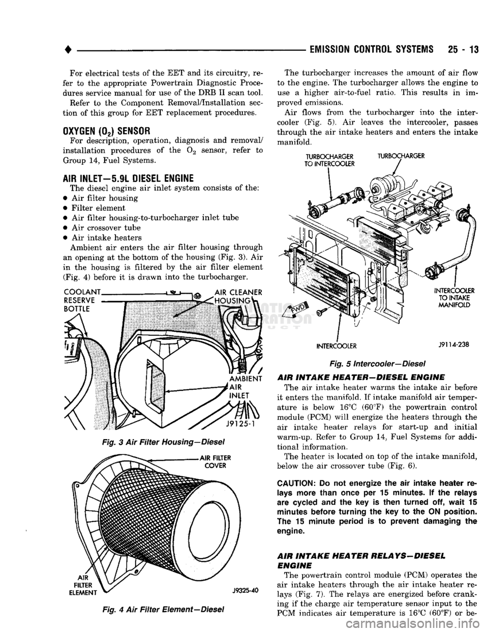
The diesel engine
air
inlet system consists
of the:
•
Air
filter housing
• Filter element •
Air
filter housing-to-turbocharger inlet tube
•
Air
crossover tube •
Air
intake heaters Ambient
air
enters
the air
filter housing through
an opening
at the
bottom
of the
housing
(Fig. 3). Air
in
the
housing
is
filtered
by the air
filter element (Fig.
4)
before
it is
drawn into
the
turbocharger.
Fig.
4 Air Filter
Element—Diesel The turbocharger increases
the
amount
of air
flow
to
the
engine.
The
turbocharger allows
the
engine
to
use
a
higher air-to-fuel ratio. This results
in im
proved emissions.
Air flows from
the
turbocharger into
the
inter-
cooler
(Fig. 5). Air
leaves
the
intercooler, passes
through
the air
intake heaters
and
enters
the
intake manifold.
TURBOCHARGER
TURBOCHARGER
TO INTERCOOLER
INTERCOOLER
J9114-238
Fig.
5
Intercooler—Diesel
AIR INTAKE HEATER-DIESEL ENGINE The
air
intake heater warms
the
intake
air
before
it enters
the
manifold.
If
intake manifold
air
temper ature
is
below
16°C
(60°F)
the
powertrain control
module
(PCM)
will energize
the
heaters through
the
air intake heater relays
for
start-up
and
initial
warm-up. Refer
to
Group
14,
Fuel Systems
for
addi
tional information. The heater
is
located
on top of the
intake manifold,
below
the air
crossover tube
(Fig. 6).
CAUTION:
Do not
energize
the air
intake heater
re
lays
more than once
per 15
minutes.
If the
relays
are cycled
and the key is
then turned
off,
wait
15
minutes
before turning
the key to the
ON
position.
The
15
minute period
is to
prevent damaging
the
engine.
AIR INTAKE HEATER RELAYS-DIESEL ENGINE The powertrain control module
(PCM)
operates
the
air intake heaters through
the air
intake heater
re
lays
(Fig. 7). The
relays
are
energized before crank
ing
if the
charge
air
temperature sensor input
to the
PCM indicates
air
temperature
is 16°C
(60°F)
or be-
Page 1494 of 1502
•
EMISSION
CONTROL SYSTEMS
25 - 17
COMPONENT REMOVAL/INSTALLATION
INDEI
page
Air
Filter/Filter
Housing—Diesel Engines
17
Air
Filter/Filter
Housing—Gas Engines
17
Air
Injection
Pump
17
Air
Injection
Pump Relief Valve
18
Check
Valve—Air
Injection
Tube
18
Coolant Temperature
Sensor
. 18
EGR
Tube—Gas Powered Engines
19
EGR
Valve
19
AIR FILTER/FILTER HOUSING-GAS ENGINES
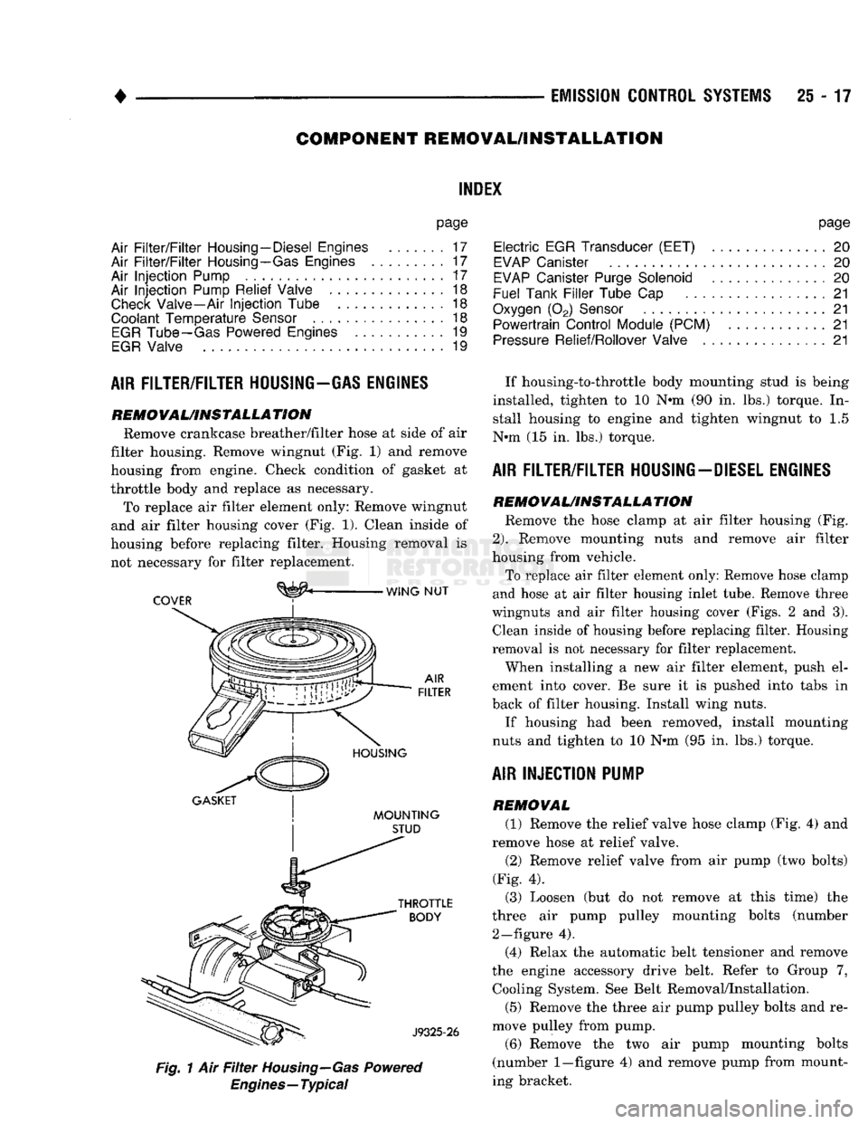
REMOVAL/INSTALLATION Remove crankcase breather/filter hose at side of air
filter housing. Remove wingnut (Fig. 1) and remove
housing from engine. Check condition of gasket at
throttle body and replace as necessary. To replace air filter element only: Remove wingnut
and air filter housing cover (Fig. 1). Clean inside of
housing before replacing filter. Housing removal is not necessary for filter replacement.
^
WING NUT
COVER
:
GASKET
| I
MOUNTING
STUD
Fig.
1 Air
Filter
Housing—Gas
Powered
Engines—Typical
page
Electric
EGR Transducer (EET)
20
EVAP
Canister
20
EVAP
Canister Purge Solenoid
20
Fuel Tank
Filler
Tube
Cap . 21
Oxygen
(02)
Sensor
21
Powertrain Control Module (PCM)
21
Pressure
Relief/Rollover Valve
21
If housing-to-throttle body mounting stud is being
installed, tighten to 10 N»m (90 in. lbs.) torque. In stall housing to engine and tighten wingnut to 1.5
N»m (15 in. lbs.) torque.
AIR FILTER/FILTER HOUSING-DIESEL ENGINES
REMO
VAL/INSTALLA
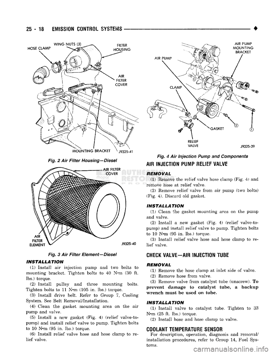
TION Remove the hose clamp at air filter housing (Fig.
2).
Remove mounting nuts and remove air filter
housing from vehicle.
To replace air filter element only: Remove hose clamp
and hose at air filter housing inlet tube. Remove three
wingnuts and air filter housing cover (Figs. 2 and 3). Clean inside of housing before replacing filter. Housing
removal is not necessary for filter replacement.
When installing a new air filter element, push el
ement into cover. Be sure it is pushed into tabs in
back of filter housing. Install wing nuts.
If housing had been removed, install mounting
nuts and tighten to 10 N»m (95 in. lbs.) torque.
AIR INJECTION PUMP
REMOVAL (1) Remove the relief valve hose clamp (Fig. 4) and
remove hose at relief valve.
(2) Remove relief valve from air pump (two bolts)
(Fig. 4). (3) Loosen (but do not remove at this time) the
three air pump pulley mounting bolts (number 2—figure 4).
(4) Relax the automatic belt tensioner and remove
the engine accessory drive belt. Refer to Group 7, Cooling System. See Belt Removal/Installation.
(5) Remove the three air pump pulley bolts and re
move pulley from pump.
(6) Remove the two air pump mounting bolts
(number
1—figure
4) and remove pump from mount
ing bracket.
Page 1495 of 1502
25
- 18
EMISSION
CONTROL
SYSTEMS
Fig. 2 Air Filter Housing—Diesel Fig. 3 Air Filter Element—Diesel INSTALLATION
(1) Install air injection pump and two bolts to
mounting bracket. Tighten bolts to 40 N*m (30 ft.
lbs.) torque. (2) Install pulley and three mounting bolts.
Tighten bolts to 11 N*m (105 in. lbs.) torque.
(3) Install drive belt. Refer to Group 7, Cooling
System. See Belt Removal/Installation.
(4) Clean the gasket mounting area on the air
pump and valve. (5) Install a new gasket (Fig. 4) (relief valve-to-
pump) and install relief valve to pump. Tighten bolts to 10 N*m (95 in. lbs.) torque.
(6) Install relief valve hose and hose clamp to re
lief valve. •
RELIEF
VALVE
J9325-39
Fig. 4 Air Injection
Pump
and
Components
AIR
INJECTION PUMP RELIEF VALVE REMOVAL
(1) Remove the relief valve hose clamp (Fig. 4) and
remove hose at relief valve.
(2) Remove relief valve from air pump (two bolts)
(Fig. 4). Discard old gasket.
INSTALLATION (1)
Clean the gasket mounting area on the pump
and valve. (2) Install a new gasket (Fig. 4) (relief valve-to-
pump) and install relief valve to pump. Tighten bolts
to 10 N*m (95 in. lbs.) torque. (3) Install relief valve hose and hose clamp to re
lief valve.
CHECK
VALVE—AIR INJECTION TUBE REMOVAL
(1) Remove the hose clamp at inlet side of valve.
(2) Remove hose from valve.
(3) Remove valve from catalyst tube (unscrew). To
prevent damage to catalyst tube, a backup
wrench must be used on tube.
INSTALLATION
(1) Install valve to catalyst tube. Tighten to 33
N«m (25 ft. lbs.) torque.
(2) Install hose and hose clamp to valve.
COOLANT TEMPERATURE SENSOR
For description, operation, diagnosis and removal/
installation procedures, refer to Group 14, Fuel Sys
tems.
Page 1496 of 1502
•
EMISSION
CONTROL SYSTEMS
25 - 19
EGR
VALVE
REMOVAL
The EGR valve and the electric EGR transducer
(EET) are serviced as one unit.
(1) Disconnect vacuum hose to EGR valve/trans
ducer assembly. Note position of hoses on EGR valve
and transducer for easier installation.
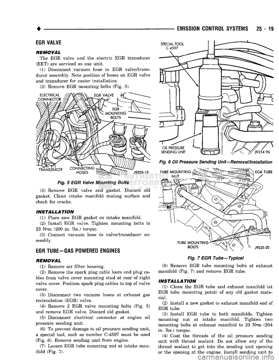
(2) Remove EGR mounting bolts (Fig. 5).
Fig.
5 EGR
Valve
Mounting
Bolts
(3) Remove EGR valve and gasket. Discard old
gasket. Clean intake manifold mating surface and
check for cracks.
INSTALLATION
(1) Place new EGR gasket on intake manifold. (2) Install EGR valve. Tighten mounting bolts to
23 N*m (200 in. lbs.) torque. (3) Connect vacuum hose to valve/transducer as
sembly.
EGR
TUBE-GAS POWERED ENGINES
REMOVAL
(1) Remove air filter housing.
(2) Remove the spark plug cable loom and plug ca
bles from valve cover mounting stud at rear of right
valve cover. Position spark plug cables to top of valve cover.
(3) Disconnect two vacuum hoses at exhaust gas
recirculation (EGR) valve. (4) Remove 2 EGR valve mounting bolts (Fig. 5)
and remove EGR valve. Discard old gasket.
(5) Disconnect electrical connector at engine oil
pressure sending unit.
(6) To prevent damage to oil pressure sending unit,
a special tool, such as number C-4597 must be used
(Fig. 6). Remove sending unit from engine.
(7) Loosen EGR tube mounting nut at intake man
ifold (Fig. 7).
Fig.
6 Oil
Pressure
Sending
Unit—Removal/Installation
Fig.
7 EGR Tube—Typical
(8) Remove EGR tube mounting bolts at exhaust
manifold (Fig. 7) and remove EGR tube.
INSTALLATION
(1) Clean the EGR tube and exhaust manifold (at
EGR tube mounting point) of any old gasket mate
rial.
(2)
Install a new gasket to exhaust manifold end of
EGR tube. (3) Install EGR tube to both manifolds. Tighten
mounting nut at intake manifold. Tighten two
mounting bolts at exhaust manifold to 23 N»m (204 in. lbs.) torque.
(4) Coat the threads of the oil pressure sending
unit with thread sealant. Do not allow any of the
thread sealant to get into the sending unit opening
or the opening at the engine. Install sending unit to