1993 DODGE TRUCK instrument cluster
[x] Cancel search: instrument clusterPage 422 of 1502
•
VEHICLE
SPEED
CONTROL SYSTEM
8H - 7
TEST
PROCEDURES
INDEX
page
Checking
for
Diagnostic
Trouble
Code
7
General
Information
7
Inoperative
System
7
Road
Test
7
Speed
Control
Cable Adjustment—Diesel Engine
. 9
Speed
Control
Cable
Attachment
10
GENERAL
INFORMATION
Before starting diagnosis and repair procedures for
a speed control malfunction, verify that the speed
control wire harness is properly connected to all con nectors. Refer to Diagnosis Chart.
ROAD
TEST
Road test vehicle to verify reports of speed control
system malfunction. The road test should include at
tention to the speedometer. Speedometer operation should be smooth and without flutter at all speeds. Flutter in the speedometer indicates a problem
which might cause surging in the speed control sys
tem. The cause of any speedometer deficiencies should be corrected before proceeding.
INOPERATIVE SYSTEM
If road test verifies a system problem and the
speedometer operates properly, check for:
• loose electrical and vacuum connections at the
servo.
• check for correct installation of the vacuum check
valve in the hose from servo to vacuum source (Gas
Engine Only). The word VAC on the valve must
point toward the vacuum source. • corrosion that should be removed from electrical
terminals and a light coating of Mopar Multi-Pur
pose Grease, or equivalent, applied. • secure attachment of both ends of speed control ca
ble.
CHECKING
FOR DIAGNOSTIC TROUBLE CODE
(1) When trying to verify a speed control system
electrical problem, use a DRB II Scan Tool to find
the cause. Refer to Powertrain Diagnostic Procedures manual. If the DRBII is not available, the Diagnostic Trou
ble Code (DTC) may be determined with the follow ing method: (a) With key inserted in ignition switch, cycle
switch to ON position 3 times. On third cycle, leave
switch in ON position. (b) After switch has been cycled 3 times, observe
Malfunction Indicator Lamp (CHECK ENGINE) on instrument cluster. If a DTC is present, the code
page
Speed
Control
Cable Attachment—Servo
10
Stop Lamp Switch Test
9
Vacuum Supply Test
....................... 9
Vehicle Speed
Control
Switch Test
. 9
Vehicle Speed
Control
System
Electrical
Tests
... 7
Vehicle Speed Sensor Test
7
will be displayed in a series of flashes representing
digits.
Three flashes in rapid succession, a slight
pause, then 4 flashes in rapid succession would in dicate DTC 34.
(2) If a DTC 34 is observed, perform the tests in
the sections Electrical Tests at Servo and Electrical
Tests at Powertrain Control Module.
If a DTC 15 is observed, perform the test for a
faulty Vehicle Speed Sensor.
(3) If a fault code 11 is observed (Diesel only), per
form the test for a faulty engine speed sensor. Refer
to the Powertrain Diagnostics Procedures Manual.
(4) Correct any problems found when performing
these tests and recheck for DTC if changes were made.
VEHICLE SPEED SENSOR TEST
For testing of the Vehicle Speed Sensor and related
components refer to the Powertrain Diagnostic Proce
dures manual.
VEHICLE SPEED CONTROL SYSTEM ELECTRICAL
TESTS
Vehicle speed control systems may be tested using
two different methods. One involves the use of the DRBII Scan Tool. If this test method is desired,
please refer to the Powertrain Diagnostic Procedures manual. The other test method uses a voltmeter. The volt
meter method is described in the following tests.
If any information is needed concerning wiring, re
fer to Group 8W - Wiring Diagrams.
CAUTION:
When test probing
for
voltage
or
continuity
at
electrical
connectors, care must
be
taken
not
to
damage connector, terminals,
or
seals.
If
these components
are
damaged,
intermittent
or
complete system
failure
may
occur.
ELECTRICAL
TESTS
AT
SERVO
(1) Turn ignition switch to ON position.
(2) Push speed control switch to ON position.
(3) Connect the negative lead of a voltmeter to a
good chassis ground near the servo.
Page 454 of 1502
•
LAMPS
8L - 11
BULB
APPLICATION
GENERAL
INFORMATION
The following Bulb Application Table lists
the
lamp title
on the
left side
of the
column
and
part
number
on the
right.
CAUTION:
Do not use
bulbs
that
have
a
higher
can
dle power than
the
bulb
listed
in the
Bulb
Applica
tion Table.
Damage
to
lamp
can
result.
EXTERIOR LAMPS
Auxiliary Turn Signal (Snow Plow) 2057
Auxiliary Headlamps (Snow Plow) .6054
Back-up....................... .......1156 Cargo Lamp..
922
Clearance Lamps
194
Front Side Marker
168
Headlamp/Sealed Beam .6052
License Plate
168
Park/Turn Signal 2057
TaiyStop/Turn Signal ...2057
INTERIOR LAMPS
DIMMER CONTROLLED LAMPS Service procedures
for
most
of the
lamps
in the in
strument panel
are
located
in
Group
8E,
Instrument
Panel
and
Gauges. Some components have lamps
that
can
only
be
serviced
by an
Authorized Service Center (ASC). These components must
be
removed
from
the
vehicle
for
service. Contact local dealer
for
location
of
nearest
ASC.
A/C Heater Control
158
Ash Receiver
..158
Gear Shift Selector...........................................PC194
Heater Control
158
Instrument Cluster.. PC 194
Radio
ASC
Snow Plow Control
.158
INDICATOR LAMPS Service procedures
for
most
of the
lamps
in the in
strument panel,
and
switches
are
located
in
Group
8E,
Instrument Panel
and
Gauges. Anti-lock Brake PC194
Brake Warning PC194 Check Engine PC194
Engine
Oil
Pressure
158
Fasten Seat Belts.. PC 194 Four Wheel Drive ....158
Hazard Flasher
194
High Beam PC194
Low Fuel....... JPC194
Maintenance Required PC 194
Transmission Temperature ..PC 194 Turn Signal PC194
NON-DIMMING LAMPS Service procedures
for
most
of the
lamps
in the
fol
lowing list
can be
found
in
Group
23,
Body.
Dome
1004
Engine Compartment ...105 Glove Compartment....
1891
Ignition Lock
ASC
Reading Lamp
912
Page 469 of 1502
8T - 2
POWER MIRRORS
•
MIRROR
SWITCH TEST PROCEDURE
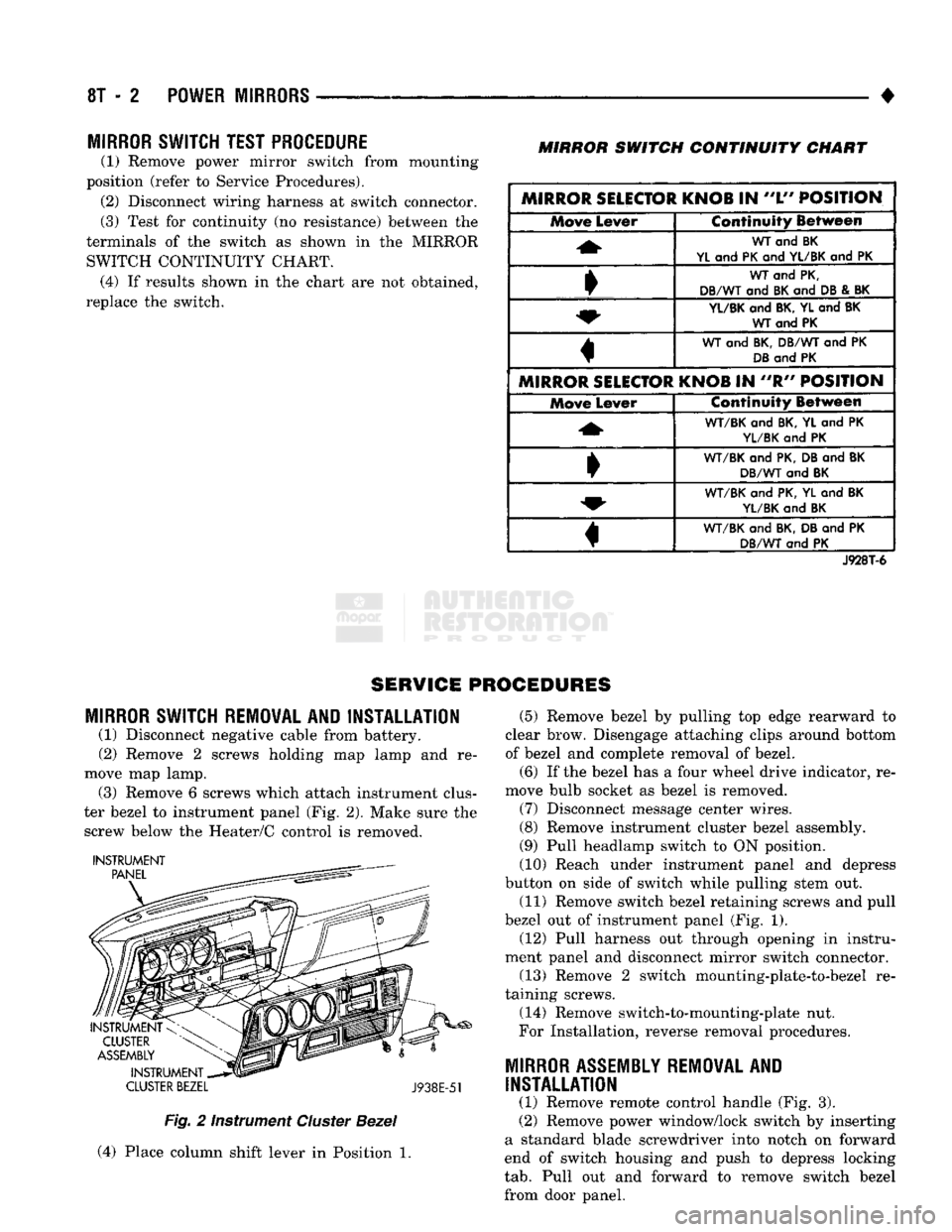
(1) Remove power mirror switch from mounting
position (refer to Service Procedures). (2) Disconnect wiring harness at switch connector.
(3) Test for continuity (no resistance) between the
terminals of the switch as shown in the MIRROR SWITCH CONTINUITY CHART. (4) If results shown in the chart are not obtained,
replace the switch.
MIRROR
SWITCH
CONTINUITY
CHART
MIRROR SELECTOR KNOB
IN
"L"
POSITION Move
Lever Continuity Between
WT
and BK
YL
and
PK
and
YL/BK
and PK
WT
and
PK,
DB/WT
and
BK
and
DB
&
BK
YL/BK
and
BK, YL
and
BK WT and PK
WT
and
BK, DB/WT
and PK
DB
and
PK
MIRROR SELECTOR KNOB
IN "R"
POSITION Move
Lever Continuity Between
WT/BK
and
BK,
YL and PK
YL/BK
and PK
•
WT/BK
and
PK, DB
and
BK
DB/WT
and
BK
WT/BK
and
PK, YL
and
BK
YL/BK
and
BK
«
WT/BK
and
BK, DB
and PK
DB/WT
and PK
J928T-6
SERVICE PROCEDURES
MIRROR
SWITCH REMOVAL AND INSTALLATION
(1) Disconnect negative cable from battery.
(2) Remove 2 screws holding map lamp and re
move map lamp. (3) Remove 6 screws which attach instrument clus
ter bezel to instrument panel (Fig. 2). Make sure the screw below the Heater/C control is removed.
INSTRUMENT
CLUSTER
BEZEL
J938E-51
Fig.
2 Instrument
Cluster
Bezel
(4) Place column shift lever in Position 1. (5) Remove bezel by pulling top edge rearward to
clear brow. Disengage attaching clips around bottom
of bezel and complete removal of bezel.
(6) If the bezel has a four wheel drive indicator, re
move bulb socket as bezel is removed. (7) Disconnect message center wires.
(8) Remove instrument cluster bezel assembly.
(9) Pull headlamp switch to ON position.
(10) Reach under instrument panel and depress
button on side of switch while pulling stem out.
(11) Remove switch bezel retaining screws and pull
bezel out of instrument panel (Fig. 1). (12) Pull harness out through opening in instru
ment panel and disconnect mirror switch connector.
(13) Remove 2 switch mounting-plate-to-bezel re
taining screws.
(14) Remove switch-to-mounting-plate nut.
For Installation, reverse removal procedures.
MIRROR
ASSEMBLY
REMOVAL
AND
INSTALLATION
(1) Remove remote control handle (Fig. 3).
(2) Remove power window/lock switch by inserting
a standard blade screwdriver into notch on forward
end of switch housing and push to depress locking
tab.
Pull out and forward to remove switch bezel
from door panel.
Page 513 of 1502
8W
- 38
WIRING
DIAGRAMS
• Wiring Diagram Name Sheet Number
EMCC
Relay
11
EMCC
Solenoid
11
Ground
11
EMCC
Relay
with Gas
Engine
11,16
EMCC
Solenoid
with Gas
Engine
11,12
Engine
Oil
Pressure Sending
Unit
.27,28
Engine
Starter
Motor
7,9
Engine
Starter
Relay
.7,9
Engine
Starter
System 1,7,8,9 Back-Up Lamp
Switch
.7,9
Bypass
Jumper
(Clutch
Pedal
Position)
8
Clutch
Pedal
Position
Switch
8
Fuse
. 7,9
Motor
7,9
Park/Neutral
Position
Switch
. .7,9
Relay
7,9
Engine Temp Sending
Unit
.
.27,28
Flasher-Hazard Warning
.56
Flasher-Turn Signal
56
Four Wheel
Drive
Indicator
Lamp
13
Front
End
Lighting
. .
.43,44
Front
End
Lighting
(Canada) 45,46
Fuel
Gauge
81,82
Fuel
Tank Gauge
Level
Sending
Unit
Diesel Engine
77
Fuel
Tank Gauge
Level
Sending
Unit
with Gas
Engine
78
Fuel
Heater
Diesel Engine
24
Fuel
Solenoid Diesel Engine
.24
Fuse
Application
Chart
1,2
Fuse
Block Module
and
Relay Bank
82
Fuses
Fuse
1 2,36
Fuse
2
.........
2,10,12,13,14,58,77,78
Fuse
3
2,7,9,10,39
Fuse
4
1,30,47
Fuse
5
1,77,78
Fuse
6
......
.1,73
Fuse
7
1,10,52
Fuse
8
.2,10,61,63
Fuse
9
.2,10,31,33,56
Fuse
10
.2,10,54,55
Fuse
11
2,10,66,67,69
Fuse
12
2,10,71
Fuse
13 1,56
Fuse
14
1,47,52,61,63
Fuse
15
1,49,51,52,61,63,75
Fusible Links 1,2,3,4,5,6,21
Gas
Engine
Wiring
Connector
89
Gauge-Fuel .77,78
Generator
.4,6
Glove
Box
Lamp
Switch
52
Hazard Warning System
. .56
Headlamp Dimmer
Switch
47
Headlamp
Switch
1,47
Headlamp
Switch
Controlled
Interior
Lamps
Headlamps 43,44,
Heated
Rear Window
(Sport
Utility)
Heater
Motor
Resistor
Heater
System Wiring Diagram Name Sheet Number
Horn System
30
Identification
Lamps-Dual Rear Wheels
41,42
Identification
Lamps-Roof Mounted
. 40
Ignition
Coil
.16
Ignition
Switch
.2,10
Ignition
Switch
System
10
Ignition
System (Gas Engine)
.........
.15,16,17,18,19,20
Automatic
Shut Down Relay
.16
Camshaft
Position
Sensor
20
Crankshaft
Position
Sensor
.18
Data
Link
Connector
* . . .17
Engine Coolant Temp
Sensor
20
EVAP
Purge Solenoid
16
Exhaust Gas
Recirculation
Solenoid
16
Fuel
Pump Relay
.16
Heated
Oxygen
Sensor
. . . 17
Idle
Air
Control
Motor
.19
Ignition
Coil
.15
Injectors
.15
Intake
Air
Temp
Sensor
. .20
Map
Sensor
. .20
Powertrain
Control
Module .15,16,17,18,19,20
Throttle
Position
(Sensor)
.18
Vehicle
Speed
Sensor
.20
Ignition
Time
Delay Relay
49
Injectors
.15 Intermittent
Wiper
System .53,54
Control
Unit
.54 Intermittent
Windshield
Wiper
Motor
54
Windshield
Washer Pump
Motor
53
Wiper
Switch
53
Key-In
Switch
49
Key-In Warning Buzzer 77,78
Lamps
Air-Conditioning
and
Heater
Switch
Lamp
48
Ash
Receiver .48,52 Back-Up Lamps
......
79,80,81
Cargo Lamp
.
.49,50 Clearance Lamps-Dual Rear Wheels .41,42
Clearance Lamps Roof Mounted
.40
Cluster
Illumination
Lamps
.
.57,58,59
Dome Lamp
50,51
Four Wheel
Drive
Indicator
.13
Glove
Box
Lamp
52
Headlamp-Left
43,45 Headlamp-Right 44,46
Headlamp
Switch
Controlled
Interior
Lamps
. 48
Heater
Switch
Lamp
.48
High Beam
Indicator
Lamp
.59
Identification
Lamp
.
.40,41
Ignition
Switch
Lamp
.49
Instrument
Panel
Illumination
Lamps
.
.57,58,59
License Lamp
. . . 80
.
.48 Low
Engine
Oil
Pressure Lamp
59
45,46
Map
Lamp
49
.
.39
Parking
Lamp-Left
Front
43,45
66,67 Parking Lamp-Right
Front
44,46 .
.66
Rear
End
Lighting
System .79,80,81
Page 857 of 1502
14 - 38
FUEL SYSTEM
•
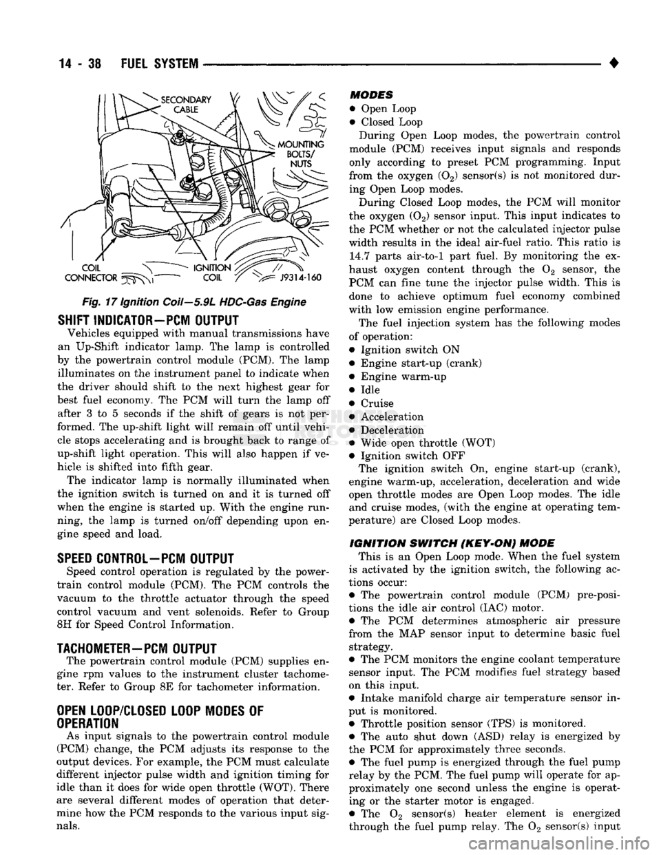
Fig.
17 Ignition Coil—5.9L
HDC-Gas
Engine
SHIFT INDICATOR-PCM
OUTPUT
Vehicles equipped with manual transmissions have
an Up-Shift indicator lamp. The lamp is controlled
by the powertrain control module (PCM). The lamp illuminates on the instrument panel to indicate when
the driver should shift to the next highest gear for
best fuel economy. The PCM will turn the lamp off after 3 to 5 seconds if the shift of gears is not per
formed. The up-shift light will remain off until vehi cle stops accelerating and is brought back to range of
up-shift light operation. This will also happen if ve
hicle is shifted into fifth gear. The indicator lamp is normally illuminated when
the ignition switch is turned on and it is turned off
when the engine is started up. With the engine run
ning, the lamp is turned on/off depending upon en
gine speed and load.
SPEED
CONTROL-PCM
OUTPUT
Speed control operation is regulated by the power-
train control module (PCM). The PCM controls the
vacuum to the throttle actuator through the speed
control vacuum and vent solenoids. Refer to Group
8H for Speed Control Information.
TACHOMETER—PCM
OUTPUT
The powertrain control module (PCM) supplies en
gine rpm values to the instrument cluster tachome ter. Refer to Group 8E for tachometer information.
OPEN
LOOP/CLOSED LOOP MODES
OF
OPERATION
As input signals to the powertrain control module
(PCM) change, the PCM adjusts its response to the
output devices. For example, the PCM must calculate
different injector pulse width and ignition timing for
idle than it does for wide open throttle (WOT). There
are several different modes of operation that deter
mine how the PCM responds to the various input sig
nals.
MODES
• Open Loop
• Closed Loop During Open Loop modes, the powertrain control
module (PCM) receives input signals and responds
only according to preset PCM programming. Input
from the oxygen (02) sensor(s) is not monitored dur
ing Open Loop modes.
During Closed Loop modes, the PCM will monitor
the oxygen (02) sensor input. This input indicates to
the PCM whether or not the calculated injector pulse width results in the ideal air-fuel ratio. This ratio is 14.7 parts air-to-1 part fuel. By monitoring the ex
haust oxygen content through the 02 sensor, the
PCM can fine tune the injector pulse width. This is done to achieve optimum fuel economy combined
with low emission engine performance.
The fuel injection system has the following modes
of operation:
• Ignition switch ON • Engine start-up (crank)
• Engine warm-up
• Idle
• Cruise • Acceleration
• Deceleration
• Wide open throttle (WOT)
• Ignition switch OFF The ignition switch On, engine start-up (crank),
engine warm-up, acceleration, deceleration and wide
open throttle modes are Open Loop modes. The idle and cruise modes, (with the engine at operating tem
perature) are Closed Loop modes.
IGNITION
SWITCH
(KEY-ON)
MODE
This is an Open Loop mode. When the fuel system
is activated by the ignition switch, the following ac
tions occur:
• The powertrain control module (PCM) pre-posi-
tions the idle air control (IAC) motor. • The PCM determines atmospheric air pressure
from the MAP sensor input to determine basic fuel strategy.
• The PCM monitors the engine coolant temperature sensor input. The PCM modifies fuel strategy based
on this input.
• Intake manifold charge air temperature sensor in
put is monitored.
• Throttle position sensor (TPS) is monitored. • The auto shut down (ASD) relay is energized by
the PCM for approximately three seconds. • The fuel pump is energized through the fuel pump
relay by the PCM. The fuel pump will operate for ap
proximately one second unless the engine is operat ing or the starter motor is engaged.
• The 02 sensor(s) heater element is energized
through the fuel pump relay. The 02 sensor(s) input
Page 1418 of 1502
•
BODY
COMPONENTS
23 - 35
CAB/BODY
INTERIOR COMPONENTS
INDEX
page
Carpets
and
Floor Mats
51
Floor Console
and
Rear Storage Tray
.........
50
Front Seats
38
Headliners
48
Instrument
Panel
35
page
Interior
Trim
Panels
. 42
Rear
Seats
41
Shoulder
Belts/Lap Belt/Buckles
45
Spare
Tire
Carrier
45
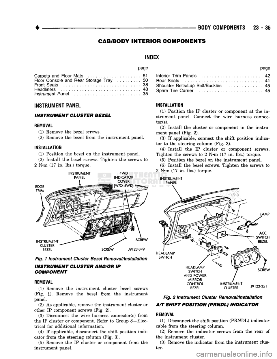
INSTRUMENT
PANEL INSTRUMENT CLUSTER BEZEL
REMOVAL
(1) Remove
the
bezel screws.
(2) Remove
the
bezel from
the
instrument panel.
INSTALLATION
(1) Position
the
bezel
on the
instrument panel.
(2) Install
the
bezel screws. Tighten
the
screws
to
2
Nnn (17 in. lbs.)
torque.
INSTRUMENT
PANEL
EDGE
TRIM
4WD
INDICATOR COVER 4WD)
INSTRUMENT CLUSTER
BEZEL
SCREW
Fig.
11nstrument
Cluster
Bezel
Removal/Installation
INSTRUMENT CLUSTER AND/OR
IP
COMPONENT
REMOVAL
(1) Remove
the
instrument cluster bezel screws
(Fig.
1).
Remove
the
bezel from
the
instrument
panel.
(2)
As
applicable, remove
the
instrument cluster
or
other
IP
component screws
(Fig. 2).
(3) Disconnect
the
wire harness connector(s) from
the
IP
cluster
or
component. Refer
to
Group 8—Elec
trical
for
additional information. (4)
If
applicable, disconnect
the
shift position indi
cator from
the
steering column
(Fig. 3).
(5) Remove
the IP
cluster
or
component from
the
instrument panel.
INSTALLATION
(1) Position
the IP
cluster
or
component
at the in
strument panel. Connect
the
wire harness connec
tors).
(2) Install
the
cluster
or
component
in the
instru
ment panel
(Fig. 2).
(3)
If
applicable, connect
the
shift position indica
tor
to the
steering column
(Fig. 3).
(4) Install
the IP
cluster
or
component screws.
Tighten
the
screws
to 2 N#m (17 in. lbs.)
torque. (5) Position
the
bezel
on the
instrument panel.
(6) Install
the
bezel screws. Tighten
the
screws
to
2
Nnn (17 in. lbs.)
torque.
INSTRUMENT
PANEL
LAMP
ACC
SWITCH
BEZEL
HEADLAMP SWITCH
HEADLAMP SWITCH
AND POWER MIRROR
CONTROL
BEZEL
SCREW
INSTRUMENT
J9123351
CLUSTER
J9123-351
Fig.
2
Instrument
Cluster
Removal/Installation
A/T SHIFT POSITION (PRNDL) INDICATOR
REMOVAL
(1) Disconnect
the
shift position (PRNDL) indicator
cable from
the
steering column.
(2) Remove
the
indicator screws from
the
rear
of
the instrument cluster. (3) Remove
the
indicator from
the
instrument clus
ter.
Page 1419 of 1502
23
- 36
BODY COMPONENTS
SCREW
INSTRUMENT
CLUSTER (REAR)
SHIFT
INDICATOR
STEERING COLUMN
J9123-539
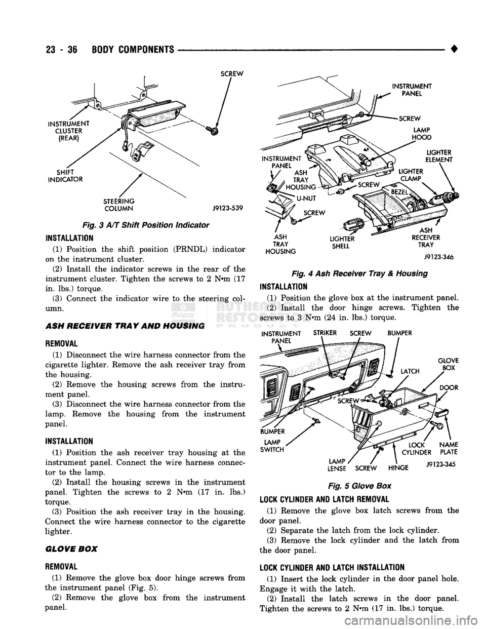
Fig.
3 A/T Shift Position Indicator
INSTALLATION
(1) Position the shift position (PRNDL) indicator
on the instrument cluster.
(2) Install the indicator screws in the rear of the
instrument cluster. Tighten the screws to 2 N»m (17
in. lbs.) torque.
(3) Connect the indicator wire to the steering col
umn.
ASH
RECEIVER
TRAY
AND
HOUSING
REMOVAL
(1) Disconnect the wire harness connector from the
cigarette lighter. Remove the ash receiver tray from
the housing. (2) Remove the housing screws from the instru
ment panel. (3) Disconnect the wire harness connector from the
lamp.
Remove the housing from the instrument
panel.
INSTALLATION
(1) Position the ash receiver tray housing at the
instrument panel. Connect the wire harness connec
tor to the lamp.
(2) Install the housing screws in the instrument
panel. Tighten the screws to 2 N«m (17 in. lbs.)
torque. (3) Position the ash receiver tray in the housing.
Connect the wire harness connector to the cigarette
lighter.
GLOVE
BOX
REMOVAL
(1) Remove the glove box door hinge screws from
the instrument panel (Fig. 5).
(2) Remove the glove box from the instrument
panel.
INSTRUMENT
PANEL
SCREW
LAMP
HOOD
PANEL
ASH
TRAY
'
HOUSING
-
LIGHTER
ELEMENT
SCREW
LIGHTER
CLAMP
ASH
TRAY
HOUSING
LIGHTER
SHELL
ASH
RECEIVER
TRAY
J9123-346
Fig.
4 Ash Receiver
Tray
&
Housing
INSTALLATION
(1) Position the glove box at the instrument panel.
(2) Install the door hinge screws. Tighten the
screws to 3 N»m (24 in. lbs.) torque.
INSTRUMENT
PANEL
STRIKER
SCREW
BUMPER
GLOVE BOX
DOOR
LAMP
SWITCH
LAMP
LENSE
SCREW
HINGE
NAME
PLATE
J9123-345
Fig.
5
Glove
Box
LOCK
CYLINDER
AND
LATCH
REMOVAL
(1) Remove the glove box latch screws from the
door panel. (2) Separate the latch from the lock cylinder.
(3) Remove the lock cylinder and the latch from
the door panel.
LOCK
CYLINDER
AND
LATCH
INSTALLATION
(1) Insert the lock cylinder in the door panel hole.
Engage it with the latch. (2) Install the latch screws in the door panel.
Tighten the screws to 2 N»m (17 in. lbs.) torque.
Page 1421 of 1502
23 - 38
BODY COMPONENTS
— —
^—_____— —
•
PAWU
NUT
WASHER
SEALS
DASH
PANEL
SEAL
SUPPORT
BRACKET
NUT
INSTRUMENT
PANEL
RELEASE
HANDLE SCREW
RETAINER'
PARKING
BRAKE
SCREW LEVER J9123-568
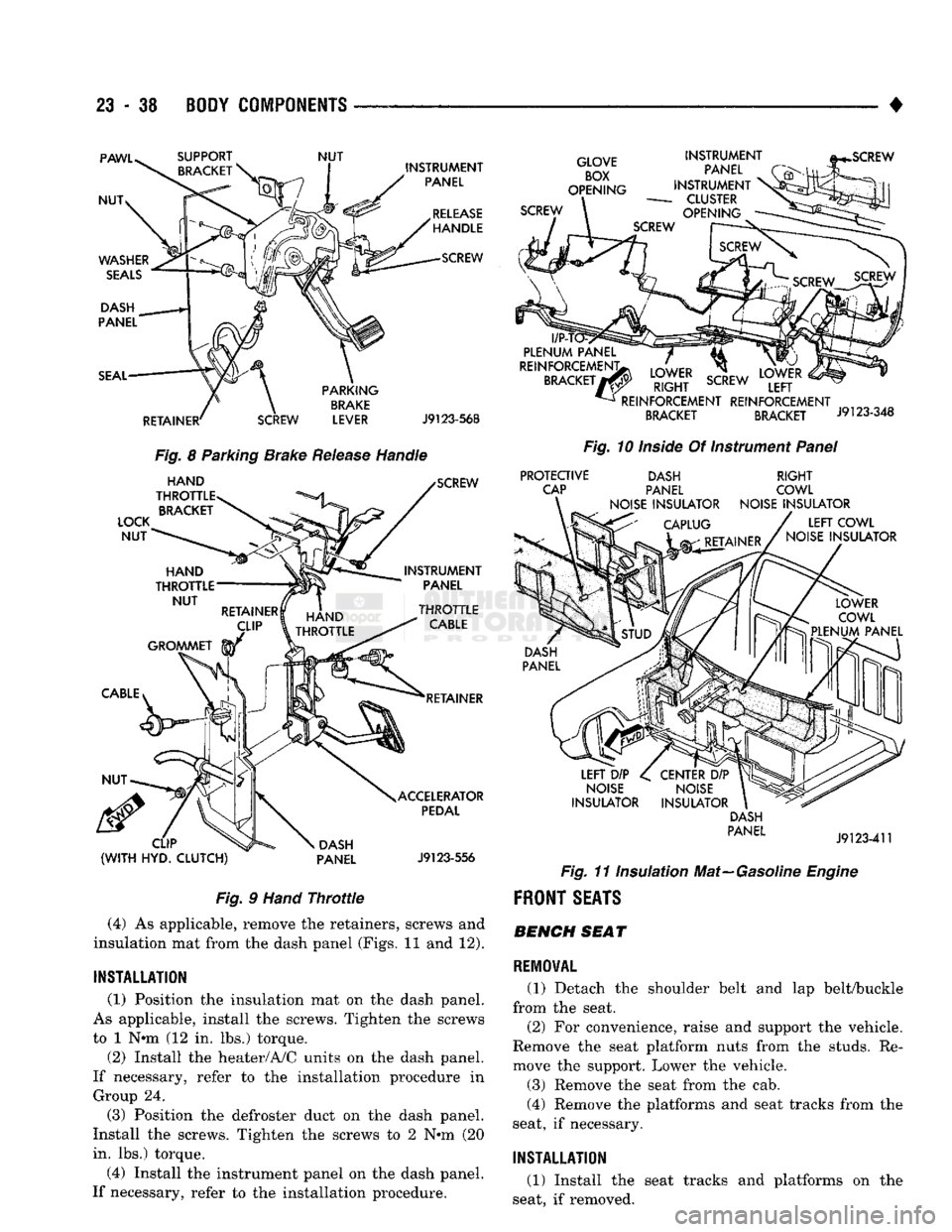
Fig.
8 Parking Brake
Release
Handle
LOCK
NUT
HAND
THROTTLE BRACKET SCREW
INSTRUMENT PANEL
HAND
^TfJlLE
>TTLE
RETAINER
CLIP
(WITH
HYD.
CLUTCH)
DASH
PANEL ACCELERATOR
PEDAL
J9123-556
Fig.
9
Hand
Throttle
(4) As applicable, remove the retainers, screws and
insulation mat from the dash panel (Figs. 11 and 12).
INSTALLATION
(1) Position the insulation mat on the dash panel.
As applicable, install the screws. Tighten the screws
to 1 N«m (12 in. lbs.) torque.
(2) Install the heater/A/C units on the dash panel.
If necessary, refer to the installation procedure in Group 24.
(3) Position the defroster duct on the dash panel.
Install the screws. Tighten the screws to 2 N*m (20
in. lbs.) torque.
(4) Install the instrument panel on the dash panel.
If necessary, refer to the installation procedure.
GLOVE
BOX
OPENING
SCREW INSTRUMENT
PANEL
INSTRUMENT
-
CLUSTER
OPENING
l/P-T
PLENUM
PANEL
REINFORCEMENT;
BRACKET
7
LOWER
RIGHT
SCREW
REINFORCEMENT REINFORCEMENT
BRACKET BRACKET J9123-348
Fig.
10
Inside
Of Instrument
Panel
PROTECTIVE
CAP DASH
PANEL
NOISE
INSULATOR
RIGHT
COWL
NOISE
INSULATOR
LEFT
COWL
NOISE
INSULATOR
LEFT
DIP
NOISE
INSULATOR
CENTER
DIP
NOISE
INSULATOR DASH
PANEL
J9123-411
Fig.
11 Insulation Mat—Gasoline
Engine
FRONT
SEATS BENCH SEAT
REMOVAL
(1) Detach the shoulder belt and lap belt/buckle
from the seat.
(2) For convenience, raise and support the vehicle.
Remove the seat platform nuts from the studs. Re
move the support. Lower the vehicle.
(3) Remove the seat from the cab.
(4) Remove the platforms and seat tracks from the
seat, if necessary.
INSTALLATION
(1) Install the seat tracks and platforms on the
seat, if removed.