1993 DODGE TRUCK instrument cluster
[x] Cancel search: instrument clusterPage 188 of 1502
•
BRAKES
BRAKES
5 - 1
CONTENTS
page
BENDIX
DISC
BRAKE
37
BRAKE
ADJUSTMENTS-BRAKE BLEEDING .. 7
BRAKE
DIAGNOSIS
3
CHRYSLER
DISC
BRAKE
27
DRUM
BRAKES-ELEVEN
INCH 46
DRUM
BRAKES-TWELVE
INCH 50
GENERAL
INFORMATION 1
MASTER
CYLINDER-COMBINATION
page
VALVE-BRAKE
LINES 10
PARKING
BRAKES
56
POWER
BRAKE
BOOSTER-BRAKE
PEDAL .. 20
POWER
BRAKE
VACUUM PUMP-DIESEL
ENGINE
...22
REAR
WHEEL ANTILOCK (RWAL)
BRAKES
.. 59
SPECIFICATIONS
65
GENERAL INFORMATION
INDEX
page
Antilock
Rear
Wheel
Brakes
1
Brake
Components 1
BRAKE
COMPONENTS
AD models are equipped with front disc and rear
drum brakes. Power assist brakes and rear wheel an
tilock brakes are standard equipment on all models. A dual reservoir master cylinder and single or dual
diaphragm, vacuum operated power brake booster is
used for all applications. Models with the Cummins
diesel engine option are also equipped with a vacuum
pump assembly to operate the power brake booster. Front disc brake units consist of single piston, slid-
ing-type calipers with semi metallic brakeshoe lin ing. Vented disc brake rotors are used on all models. Bendix calipers are used on 4-wheel drive models
and on diesel engine models. Chrysler disc brake cal
ipers are used for all other applications. Rear drum brakes are dual shoe units with an au
tomatic adjustment mechanism. Bendix and Chrysler drum brake assemblies are used. A combination valve is used on all models. The
valve consists of a front brake metering (hold-off)
valve and a front/rear pressure differential switch. A red, brake indicator and warning light is used to
alert the driver if a pressure differential exists be
tween the front and rear hydraulic systems. The light also alerts the driver when the parking brakes
are applied. The light is located at the left side of the
instrument cluster. An additional indicator light is used for the anti-
lock system. This light is amber and is located in the
page
Brake
Fluid/Lubricants/Cleaning
Solvents
1
Brake
Safety Precautions 2
same side of the instrument cluster as the red indi
cator light. The antilock light alerts the driver if a system fault occurs.
ANTILOCK
REAR
WHEEL
BRAKES
All AD models are equipped with antilock rear
brakes. The system is designed to retard wheel lockup during periods of high wheel slip when brak
ing. Retarding wheel lockup is accomplished by modu
lating fluid pressure to the wheel brake units. Refer
to the Rear Wheel Anti-Lock Brake section for oper ation and service information.
BRAKE
FLUID/LUBRICANTS/CLEANING SOLVENTS Recommended fluid for all AD models is Mopar
brake fluid or equivalent meeting SAE J1703 and DOT 3 standards. Use Mopar multi mileage grease to lubricate cali
per slide surfaces, drum brake pivot pins and shoe contact points on the backing plates. Use GE 661 or
Dow 111 silicone grease (or equivalent) on caliper
bushings and slide pins. Use fresh brake fluid or Mopar brake cleaner to
clean or flush brake system components. These are
the only cleaning materials recommended.
Page 382 of 1502
• • ^ ^ ^ INSTRUMENT PANEL AND GAUGES 8E - 1
CONTENTS
page
CLUSTER AND GAUGE SERVICE PROCEDURES . 12
CLUSTER AND GAUGE TEST PROCEDURES .. i
GENERAL INFORMATION . 1
page
MESSAGE CENTER-DIESEL ENGINE ........ 4
MESSAGE CENTER-GAS ENGINE .......... 3
SWITCH
AND PANEL COMPONENT SERVICE . 16
GENERAL
INFORMATION
INDEX
page
Generator
Indicating
System
2
Distance
Sensor
2
Electronic
Digital
Clock
3
Fuel
Level
Indicating
System
1
page
Malfunction
Indicator
(Check
Engine)
3
Oil
Pressure
Warning
Lamp
................. 2
Speedometer/Odometer
System
2
Temperature
and Oil
Indicating
System
......... 2
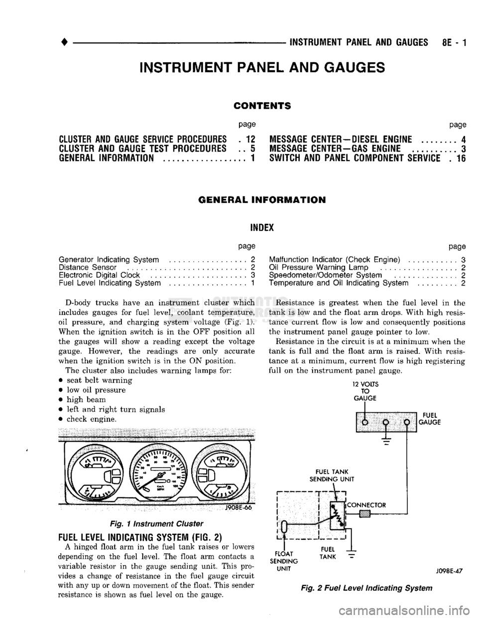
D-body trucks have an instrument cluster which
includes gauges for fuel level, coolant temperature,
oil pressure, and charging system voltage (Fig. 1).
When the ignition switch is in the OFF position all
the gauges will show a reading except the voltage gauge. However, the readings are only accurate
when the ignition switch is in the ON position.
The cluster also includes warning lamps for:
• seat belt warning
• low oil pressure
• high beam
• left and right turn signals
• check engine. J908E-66
Fig.
11nstrument
Cluster
FUEL LEVEL INDICATING SYSTEM (FIG. 2)
A hinged float arm in the fuel tank raises or lowers
depending on the fuel level. The float arm contacts a
variable resistor in the gauge sending unit. This pro
vides a change of resistance in the fuel gauge circuit
with any up or down movement of the float. This sender
resistance is shown as fuel level on the gauge. Resistance is greatest when the fuel level in the
tank is low and the float arm drops. With high resis
tance current flow is low and consequently positions
the instrument panel gauge pointer to low.
Resistance in the circuit is at a minimum when the
tank is full and the float arm is raised. With resis
tance at a minimum, current flow is high registering
full on the instrument panel gauge.
12
VOLTS
TO
GAUGE
IP
FUEL
TANK
SENDING
UNIT
FLOAT
SENDING
UNIT
1:
1
j
^
fCONNECTOR
!g|yj-»—
FUEL
GAUGE
FUEL
TANK
J098E-47
Fig.
2
Fuel
Level
Indicating
System
INSTRUMENT PANEL AND GAUGES
Page 383 of 1502
8E
- 2
INSTRUMENT PANEL
AND
GAUGES
•
TEMPERATURE AND
OIL
INDICATING SYSTEM
(FIG.
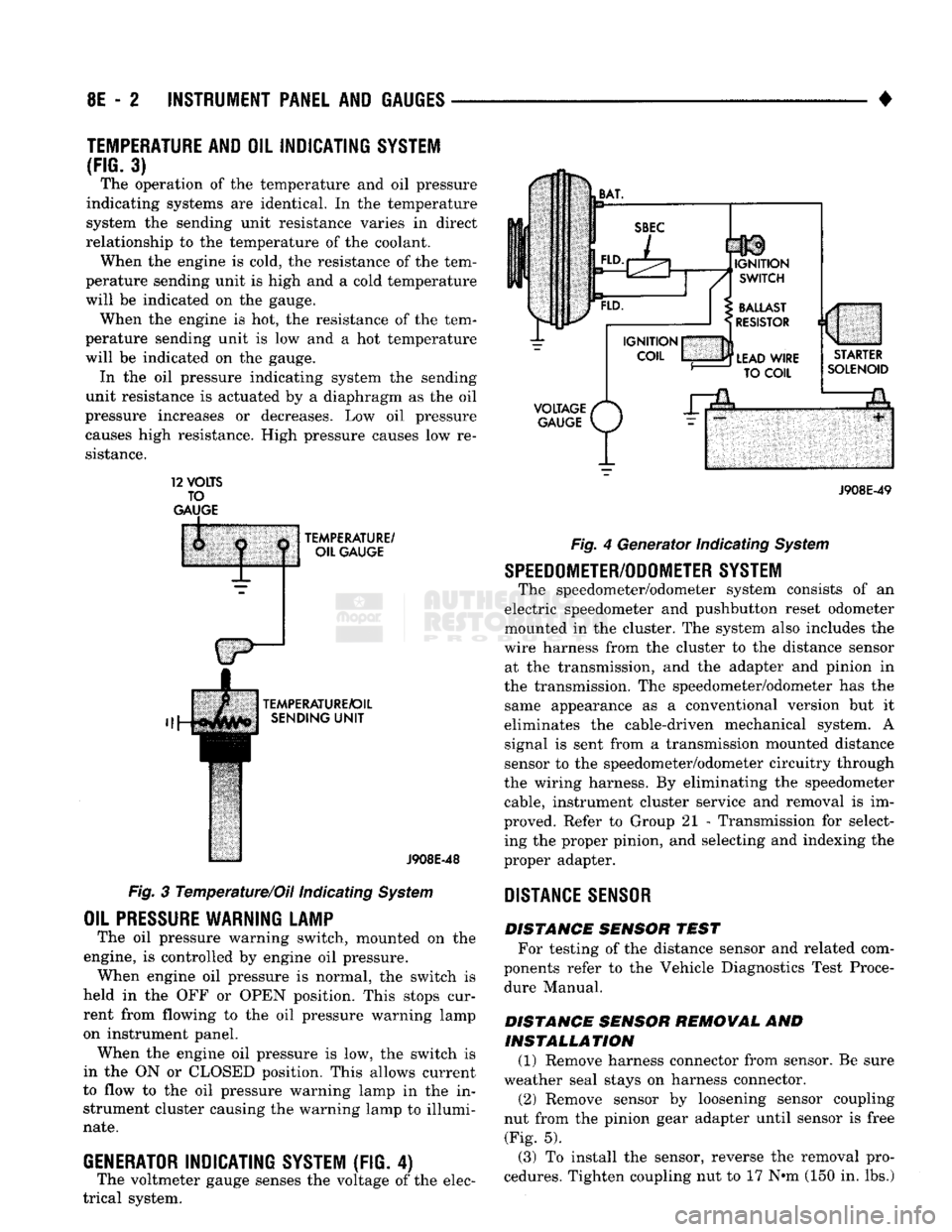
3) The operation of the temperature and oil pressure
indicating systems are identical. In the temperature
system the sending unit resistance varies in direct
relationship to the temperature of the coolant. When the engine is cold, the resistance of the tem
perature sending unit is high and a cold temperature
will be indicated on the gauge. When the engine is hot, the resistance of the tem
perature sending unit is low and a hot temperature
will be indicated on the gauge. In the oil pressure indicating system the sending
unit resistance is actuated by a diaphragm as the oil
pressure increases or decreases. Low oil pressure causes high resistance. High pressure causes low re
sistance. 12
VOLTS
TO
GAUGE
TEMPERATURE/
OIL GAUGE
TEMPERATURE/OIL SENDING
UNIT
J908E-48
Fig. 3 Temperature/Oil indicating System
OIL
PRESSURE
WARNING LAMP
The oil pressure warning switch, mounted on the
engine, is controlled by engine oil pressure. When engine oil pressure is normal, the switch is
held in the OFF or OPEN position. This stops cur
rent from flowing to the oil pressure warning lamp
on instrument panel. When the engine oil pressure is low, the switch is
in the ON or CLOSED position. This allows current
to flow to the oil pressure warning lamp in the in strument cluster causing the warning lamp to illumi
nate.
GENERATOR
INDICATING
SYSTEM
(FIG. 4)
The voltmeter gauge senses the voltage of the elec
trical system.
VOLTAGE
/*
GAUGE
P/
J908E-49 Fig. 4 Generator Indicating System
SPEEDOMETER/ODOMETER SYSTEM
The speedometer/odometer system consists of an
electric speedometer and pushbutton reset odometer
mounted in the cluster. The system also includes the
wire harness from the cluster to the distance sensor at the transmission, and the adapter and pinion in
the transmission. The speedometer/odometer has the same appearance as a conventional version but it
eliminates the cable-driven mechanical system. A signal is sent from a transmission mounted distance
sensor to the speedometer/odometer circuitry through
the wiring harness. By eliminating the speedometer cable, instrument cluster service and removal is im
proved. Refer to Group 21 - Transmission for select ing the proper pinion, and selecting and indexing the
proper adapter.
DISTANCE
SENSOR
DISTANCE SENSOR TEST For testing of the distance sensor and related com
ponents refer to the Vehicle Diagnostics Test Proce dure Manual.
DISTANCE SENSOR REMOVAL AND INSTALLATION (1) Remove harness connector from sensor. Be sure
weather seal stays on harness connector. (2) Remove sensor by loosening sensor coupling
nut from the pinion gear adapter until sensor is free (Fig. 5).
(3) To install the sensor, reverse the removal pro
cedures. Tighten coupling nut to 17 N»m (150 in. lbs.)
Page 386 of 1502
•
INSTRUMENT PANEL
AND
GAUGES
8E - 5
CLUSTER
AND
GAUGE TEST
PROCEDURES
INDEX
page
Fuel Gauge
Circuit
Test
9
Fuel Tank Sending
Unit
Test
5
Oil Pressure Gauge
Circuit
Test
..............
9
Sending
Unit
(Sensor) Test
5
page
Speedometer
10
Temperature
Gauge
Circuit
Test
8
Voltage Gauge
Circuit
Test
10
Warning Lamp System Tests
6
CAUTION:
Disconnect
battery
negative cable,
in
en
gine compartment, before servicing instrument panel. When power
is
required
for
test purposes,
connect
battery
cable
(for
test only).
Disconnect battery negative cable after test
and before continuing service procedures.
SENDING
UNIT
(SENSOR) TEST
When
a
problem occurs with
a
cluster gauge,
be
fore disassembling
the
cluster
to
check
the
gauge, check
for a
defective sending unit (sensor)
or
wiring.
(1) Sending units
and
wiring
can be
checked
by
grounding
the
connector leads,
at the
sending unit,
in
the
vehicle.
CAUTION:
When connecting
an
input
terminal
to
ground,
Do Not
leave
the
connection grounded
for
more than
a
few
seconds.
(2) With
the
ignition
in the ON
position;
a
grounded input will cause
the oil,
fuel
or
tempera
ture gauge
to
read
at or
above maximum.
FUEL TANK SENDING
UNIT
TEST
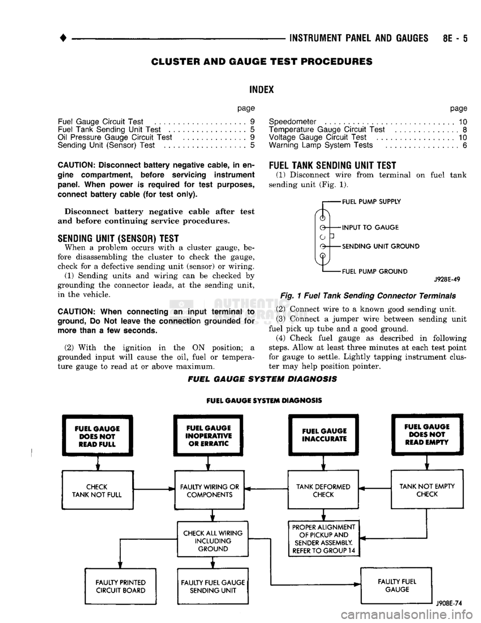
(1) Disconnect wire from terminal
on
fuel tank
sending unit (Fig.
1).
FUEL PUMP SUPPLY
INPUT
TO
GAUGE
SENDING
UNIT
GROUND
FUEL PUMP GROUND
J928E-49
Fig.
1
Fuel
Tank
Sending
Connector
Terminals
(2) Connect wire
to a
known good sending unit.
(3) Connect
a
jumper wire between sending unit
fuel pick
up
tube
and a
good ground.
(4) Check fuel gauge
as
described
in
following
steps.
Allow
at
least three minutes
at
each test point
for gauge
to
settle. Lightly tapping instrument clus
ter
may
help position pointer.
FUEL GAUGE SYSTEM DIAGNOSIS
FUEL GAUGE SYSTEM DIAGNOSIS FUEL GAUGE
DOES
NOT
READ
FULL FAULTY PRINTED
CIRCUIT BOARD FUEL GAUGE
INOPERATIVE OR ERRATIC FUEL GAUGE
INACCURATE
E
1
I
CHECK
FAULTY WIRING
OR
TANK DEFORMED
TANK
NOT
FULL COMPONENTS
CHECK
CHECK
ALL WIRING INCLUDING GROUND
i
FAULTY FUEL GAUGE SENDING
UNIT
i 1
FUEL
C
1
DOES
1
READ
1
pAUGE
I
>N0?
1
EMPTY
1
r
TANK
NOT
EMPTY
CHECK
PROPER
ALIGNMENT
OF PICKUP AND
SENDER
ASSEMBLY.
REFER
TO
GROUP
14
FAULTY FUEL
GAUGE
J908E-74
Page 387 of 1502
8E
- 6
INSTRUMENT PANEL
AND
GAUGES
•
(5)
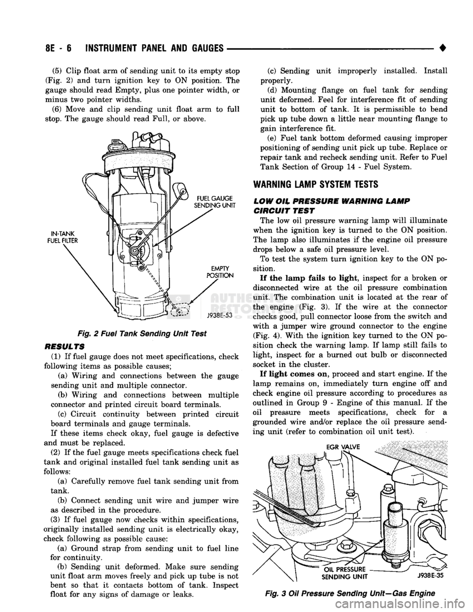
Clip float arm of sending unit to its empty stop
(Fig. 2) and turn ignition key to ON position. The
gauge should read Empty, plus one pointer width, or
minus two pointer widths.
(6) Move and clip sending unit float arm to full
stop.
The gauge should read Full, or above.
Fig. 2 Fuel Tank Sending Unit Test
RESULTS (1) If fuel gauge does not meet specifications, check
following items as possible causes; (a) Wiring and connections between the gauge
sending unit and multiple connector. (b) Wiring and connections between multiple
connector and printed circuit board terminals.
(c) Circuit continuity between printed circuit
board terminals and gauge terminals.
If these items check okay, fuel gauge is defective
and must be replaced.
(2) If the fuel gauge meets specifications check fuel
tank and original installed fuel tank sending unit as follows:
(a) Carefully remove fuel tank sending unit from
tank.
(b) Connect sending unit wire and jumper wire
as described in the procedure.
(3) If fuel gauge now checks within specifications,
originally installed sending unit is electrically okay,
check following as possible cause:
(a) Ground strap from sending unit to fuel line
for continuity. (b) Sending unit deformed. Make sure sending
unit float arm moves freely and pick up tube is not
bent so that it contacts bottom of tank. Inspect float for any signs of damage or leaks. (c) Sending unit improperly installed. Install
properly.
(d) Mounting flange on fuel tank for sending
unit deformed. Feel for interference fit of sending
unit to bottom of tank. It is permissible to bend
pick up tube down a little near mounting flange to gain interference fit.
(e) Fuel tank bottom deformed causing improper
positioning of sending unit pick up tube. Replace or
repair tank and recheck sending unit. Refer to Fuel
Tank Section of Group 14 - Fuel System.
WARNING
LAMP
SYSTEM
TESTS
LOW
OH.
PRESSURE WARNING LAMP CIRCUIT
TEST
The low oil pressure warning lamp will illuminate
when the ignition key is turned to the ON position.
The lamp also illuminates if the engine oil pressure drops below a safe oil pressure level.
To test the system turn ignition key to the ON po
sition.
If the lamp fails to light, inspect for a broken or
disconnected wire at the oil pressure combination
unit. The combination unit is located at the rear of
the engine (Fig. 3). If the wire at the connector checks good, pull connector loose from the switch and
with a jumper wire ground connector to the engine (Fig. 4). With the ignition key turned to the ON po
sition check the warning lamp. If lamp still fails to
light, inspect for a burned out bulb or disconnected
socket in the cluster.
If light comes on, proceed and start engine. If the
lamp remains on, immediately turn engine off and
check engine oil pressure according to procedures as
outlined in Group 9 - Engine of this manual. If the
oil pressure meets specifications, check for a
grounded wire and/or replace the oil pressure send
ing unit (refer to combination oil unit test). Fig. 3 Oil Pressure Sending Unit—Gas Engine
Page 393 of 1502
8E
- 12
INSTRUMENT PANEL
AND
GAUGES
•
CLUSTER AND GAUGE
SERVICE
PROCEDURES
INDEX
page
Cluster Bezel
12
Cluster
Mask
and
Lens
12
Fuel Gauge
13
Instrument
Cluster Assembly
12
Lamp Bulb Replacement—Message Center
..... 15
CLUSTER
BEZEL
REMOVAL
(1) Disconnect negative cable from battery.
(2) Tape
or
cover steering column
to
prevent dam
age
to
paint.
(3) Remove
2
screws and remove map lamp.
CAUTION:
Map
lamp must
be
removed
to
prevent
damage
to
instrument panel.
(4) Remove
6
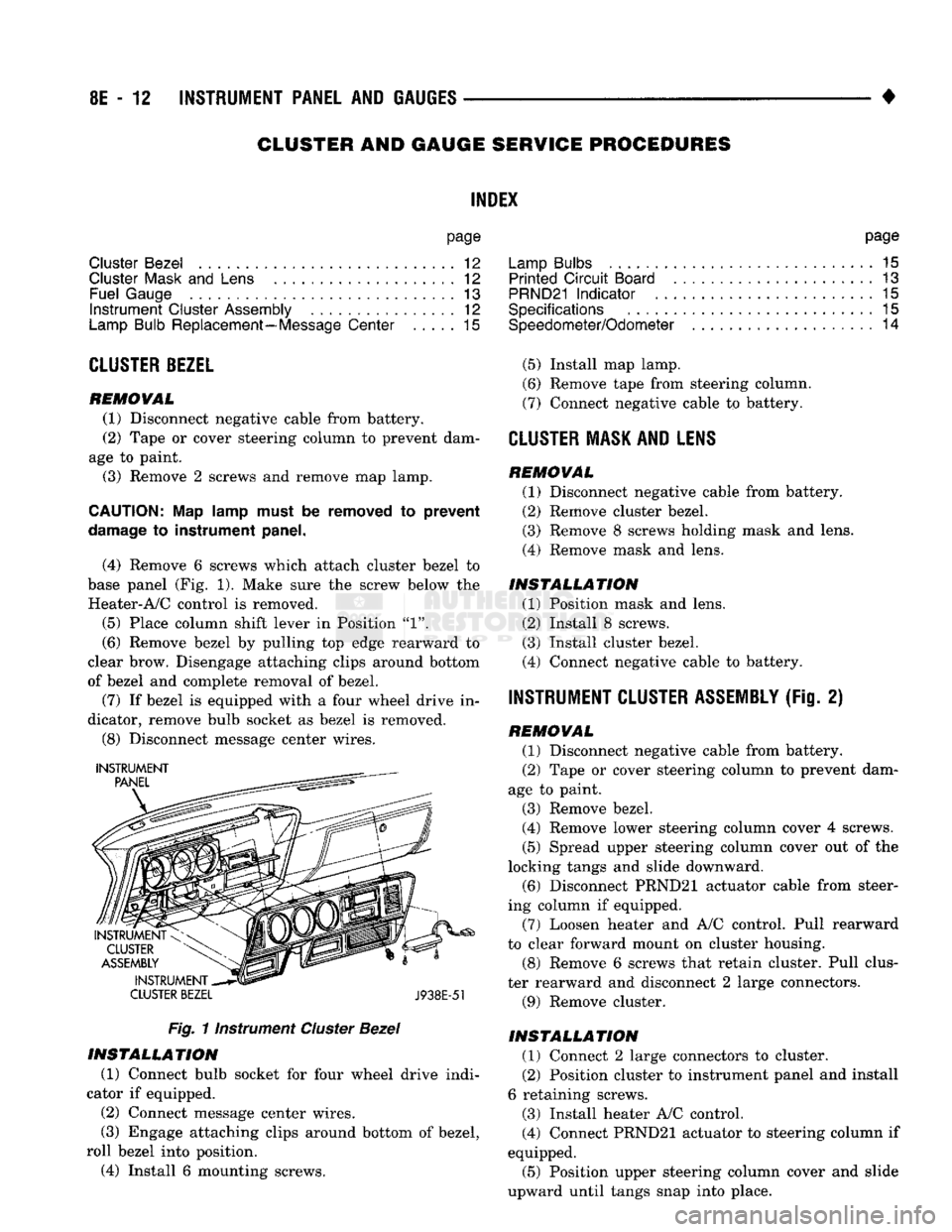
screws which attach cluster bezel
to
base panel (Fig.
1).
Make sure
the
screw below
the
Heater-A/C control
is
removed.
(5)
Place column shift lever
in
Position
"1".
(6) Remove bezel
by
pulling
top
edge rearward
to
clear brow. Disengage attaching clips around bottom
of bezel
and
complete removal
of
bezel.
(7)
If
bezel
is
equipped with
a
four wheel drive
in
dicator, remove bulb socket
as
bezel
is
removed.
(8) Disconnect message center wires.
INSTRUMENT
CLUSTER BEZEL
J938E-51
Fig.
1 instrument
Cluster
Bezel
INSTALLATION
(1) Connect bulb socket
for
four wheel drive indi
cator
if
equipped.
(2)
Connect message center wires.
(3) Engage attaching clips around bottom
of
bezel,
roll bezel into position.
(4) Install
6
mounting screws. page
Lamp Bulbs
. . 15
Printed
Circuit
Board
13
PRND21
Indicator
. 15
Specifications
15
Speedometer/Odometer
14
(5)
Install map lamp.
(6) Remove tape from steering column.
(7) Connect negative cable
to
battery.
CLUSTER
MASK AND LENS REMOVAL
(1) Disconnect negative cable from battery.
(2) Remove cluster bezel.
(3) Remove
8
screws holding mask
and
lens.
(4) Remove mask
and
lens.
INSTALLATION
(1) Position mask
and
lens.
(2) Install
8
screws.
(3) Install cluster bezel.
(4) Connect negative cable
to
battery.
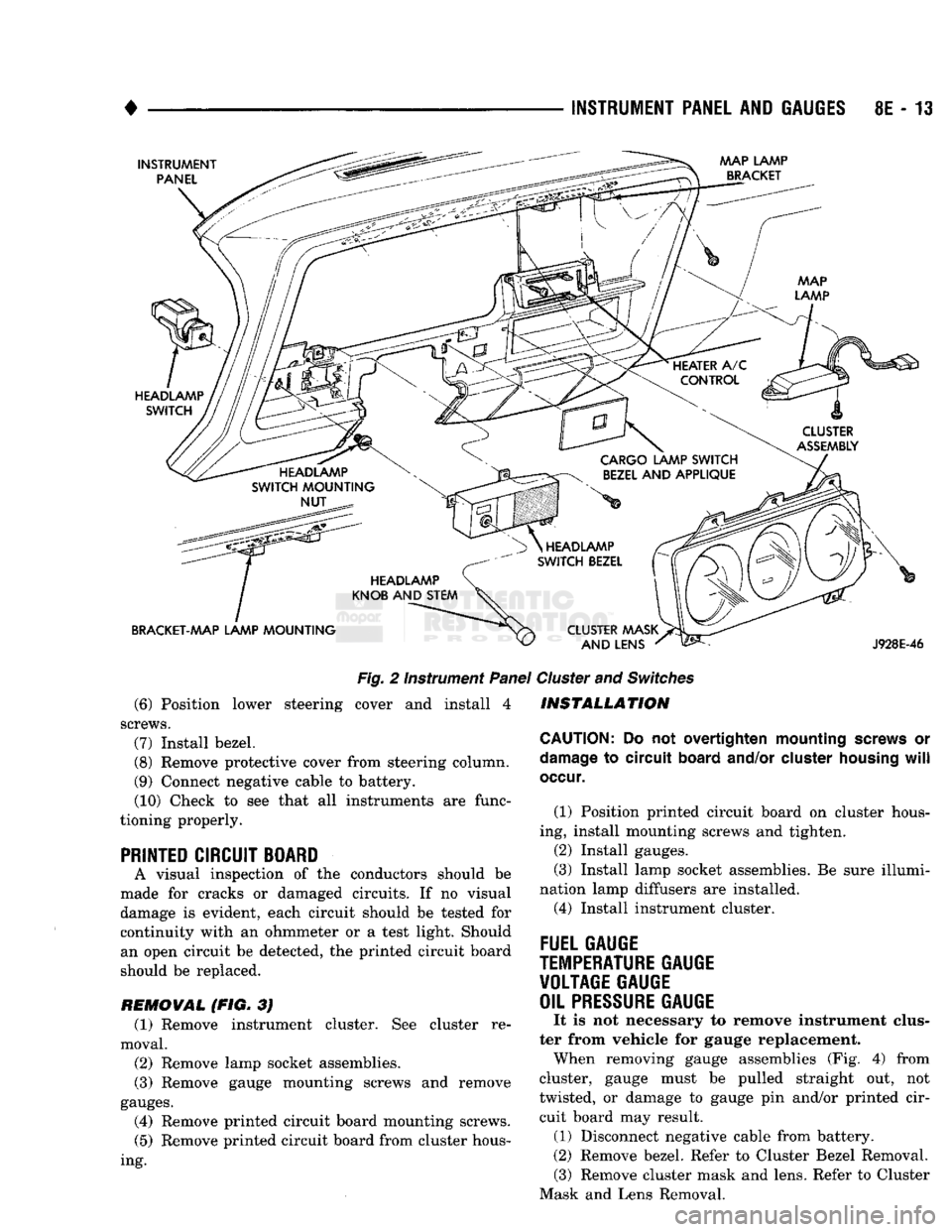
INSTRUMENT CLUSTER ASSEMBLY
(Fig.
2)
REMOVAL
(1) Disconnect negative cable from battery.
(2) Tape
or
cover steering column
to
prevent dam
age
to
paint.
(3) Remove bezel.
(4) Remove lower steering column cover
4
screws.
(5)
Spread upper steering column cover
out of
the
locking tangs
and
slide downward. (6) Disconnect PRND21 actuator cable from steer
ing column
if
equipped.
(7) Loosen heater
and
A/C control. Pull rearward
to clear forward mount
on
cluster housing.
(8) Remove
6
screws that retain cluster. Pull clus
ter rearward
and
disconnect
2
large connectors.
(9) Remove cluster.
INSTALLATION
(1) Connect
2
large connectors
to
cluster.
(2) Position cluster
to
instrument panel and install
6 retaining screws.
(3) Install heater A/C control.
(4) Connect PRND21 actuator
to
steering column
if
equipped.
(5)
Position upper steering column cover
and
slide
upward until tangs snap into place.
Page 394 of 1502
INSTRUMENT PANEL
AND
GAUGES
8E - 13
INSTRUMENT
PANEL MAP LAMP
BRACKET
HEADLAMP
SWITCH
CLUSTER
ASSEMBLY
HEADLAMP
SWITCH
MOUNTING
NUT CARGO LAMP
SWITCH
BEZEL
AND
APPLIQUE
HEADLAMP
KNOB
AND
STEM
BRACKET-AAAP LAMP
MOUNTING
Fig.
2 Instrument
Panel
(6) Position lower steering cover and install 4
screws.
(7)
Install bezel.
(8)
Remove protective cover from steering column.
(9) Connect negative cable to battery. (10) Check to see that all instruments are func
tioning properly.
PRINTED CIRCUIT BOARD
A visual inspection of the conductors should be
made for cracks or damaged circuits. If no visual
damage is evident, each circuit should be tested for continuity with an ohmmeter or a test light. Should an open circuit be detected, the printed circuit board
should be replaced.
REMOVAL (FIG. 3J (1) Remove instrument cluster. See cluster re
moval.
(2)
Remove lamp socket assemblies.
(3) Remove gauge mounting screws and remove
gauges.
(4) Remove printed circuit board mounting screws.
(5)
Remove printed circuit board from cluster hous
ing.
HEADLAMP
SWITCH
BEZEL
CLUSTER MASK AND LENS
J928E-46
Cluster
and
Switches
INSTALLATION
CAUTION:
Do not overtighten mounting
screws
or
damage
to circuit
board
and/or
cluster
housing
will
occur.
(1) Position printed circuit board on cluster hous
ing, install mounting screws and tighten.
(2)
Install gauges.
(3) Install lamp socket assemblies. Be sure illumi
nation lamp diffusers are installed. (4) Install instrument cluster.
FUEL GAUGE
TEMPERATURE
GAUGE VOLTAGE GAUGE
OIL
PRESSURE
GAUGE
It is not necessary to remove instrument clus
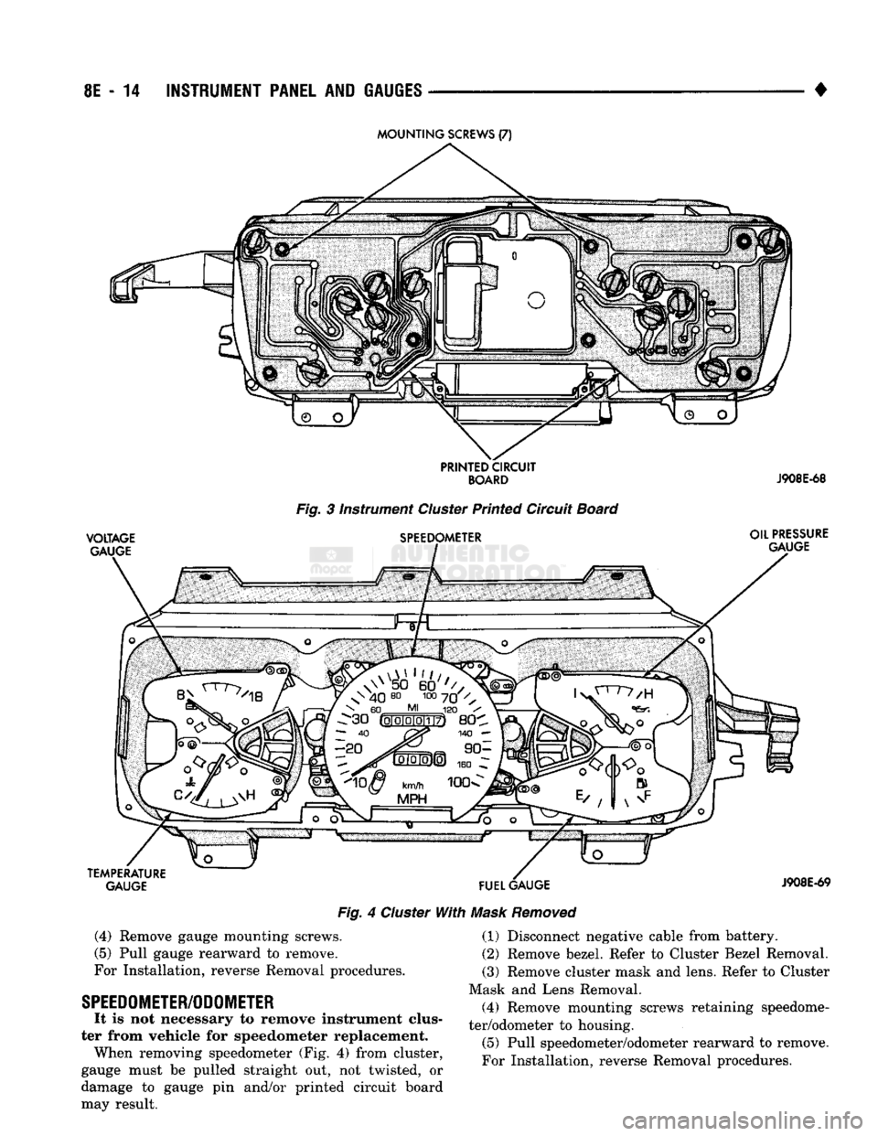
ter from vehicle for gauge replacement. When removing gauge assemblies (Fig. 4) from
cluster, gauge must be pulled straight out, not
twisted, or damage to gauge pin and/or printed cir cuit board may result. (1) Disconnect negative cable from battery.
(2)
Remove bezel. Refer to Cluster Bezel Removal. (3) Remove cluster mask and lens. Refer to Cluster
Mask and Lens Removal.
Page 395 of 1502
8E
- 14
INSTRUMENT
PANEL
AND
GAUGES
•
VOLTAGE
GAUGE
Fig. 3 instrument Cluster Printed Circuit Board
SPEEDOMETER OIL
PRESSURE
GAUGE
TEMPERATURE GAUGE
FUEL
GAUGE
Fig. 4 Cluster With Mask Removed
J908E-69
(4)
Remove gauge mounting screws.
(5) Pull gauge rearward to remove.
For Installation, reverse Removal procedures.
SPEEDOMETER/ODOMETER
It is not necessary to remove instrument clus
ter from vehicle for speedometer replacement. When removing speedometer (Fig. 4) from cluster,
gauge must be pulled straight out, not twisted, or
damage to gauge pin and/or printed circuit board
may result. (1) Disconnect negative cable from battery.
(2) Remove bezel. Refer to Cluster Bezel Removal.
(3) Remove cluster mask and lens. Refer to Cluster
Mask and Lens Removal. (4) Remove mounting screws retaining speedome
ter/odometer to housing.
(5) Pull speedometer/odometer rearward to remove.
For Installation, reverse Removal procedures.