1993 DODGE TRUCK instrument cluster
[x] Cancel search: instrument clusterPage 396 of 1502
•
INSTRUMENT PANEL
AND
GAUGES
8E - 15
PRND21 INDICATOR
REMOVAL
(1) Remove bezel. Refer to Cluster Bezel Removal.
(2)
Remove cluster mask and lens. Refer to Cluster
Mask and Lens Removal. (3) Remove cluster assembly. Refer to Instrument
Cluster Removal. (4) Remove screws attaching PRND21 mechanism
to cluster housing.
(5)
Remove PRND21 mechanism.
INSTALLATION (1) Position PRND21 mechanism to cluster hous
ing. (2) Install mounting screws.
(3)
Install cluster assembly. (4) Install mask-lens.
(5)
Install bezel.
LAMP BULBS
CLUSTER ILLUMINATION LAMPS TURN SIGNAL INDICATOR LAMPS
LOW OIL PRESSURE INDICATOR LAMP
HIGH BEAM INDICATOR LAMP CHECK ENGINE LAMP
SEAT BELT WARNING LAMP
REMOVAL (1) Disconnect negative cable from battery.
(2) Remove instrument cluster. See cluster re
moval.
(3)
Twist lamp socket assembly and remove from
printed circuit board. (4) Remove bulb from socket.
INSTALLATION (1) Install bulb into socket.
(2) Install socket assembly into printed circuit
board.
(3)
Position cluster into place in panel. See cluster
installation. (4) Connect battery negative cable.
LAMP BULB REPLACEMENT—MESSAGE CENTER
REMOVAL (1) Disconnect battery negative cable.
(2) Remove instrument cluster bezel assembly. Re
fer to Instrument Cluster removal.
(3)
Twist lamp socket assembly and remove from
printed circuit board. (4) Remove bulb from socket.
INSTALLATION (1) Install bulb into socket assembly. (2) Install lamp socket assembly into printed cir
cuit board.
(3)
Install Instrument Cluster bezel assembly to
instrument panel. Refer to Instrument Cluster instal
lation.
(4) Connect negative cable from battery.
FOUR WHEEL DRIVE INDICATOR LAMP (1) Pull bulb and socket assembly from rear of
housing. (2) Remove bulb from socket.
(3)
Reverse removal procedures to install.
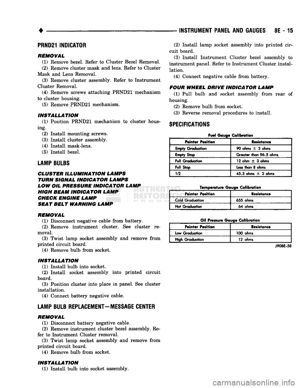
SPECIFICATIONS
Fuel
Gauge Calibration
Mntar Position Resistance
Empty Graduation 90
ohms
± 3
ohms
Empty Stop
Greater
than
96.5 ohms
Full
Graduation 12 ohm
± 3
ohms
Full
Stop
Less
than
8
ohms
1/2
45.3 ohms
± 3
ohms
Temperature
Gauge
Calibration
Pointer
Position Resistance
Cold Graduation 655 ohms
Hot Graduation 64 ohms
Oil Pressure Gauge Calibration
Pointer
Position Resistance
Low Graduation 100 ohms
High Graduation 12 ohms
J908E-58
Page 397 of 1502
8E - 16 INSTRUMENT PANEL AND GAUGES
• SWITCH AND
PANEL
COMPONENT
SERVICE
INDEX
page
Ash
Tray
20
Cigar
Lighter
........................ 20
Four
Wheel Drive
Indicator
19
Fuse
Block
and
Flashers
................... 19
Glove
Box 21
Heater A/C Control
17
page
Heater Control
16
Hood
Release
19
Illumination
Bulb Replacement
22
Message
Center Module
................... 18
Steering Column Lowering
and
Raising
16
Switches
17
DISCONNECT NEGATIVE CABLE FEOM
BATTERY IN ENGINE COMPAETMENT BE FORE SERVICING INSTRUMENT PANEL.
STEERING COLUMN LOWERING AND RAISING When servicing the instrument panel and the Low
ering and Raising of the steering column is required,
the following is the procedure for doing so: This procedure is not for removing and replac
ing the steering column. Refer to Group - 19 Steering of this manual for the removal and re
placement procedures.
LOWERING STEERING COLUMN
(1) Disconnect negative cable from battery.
(2)
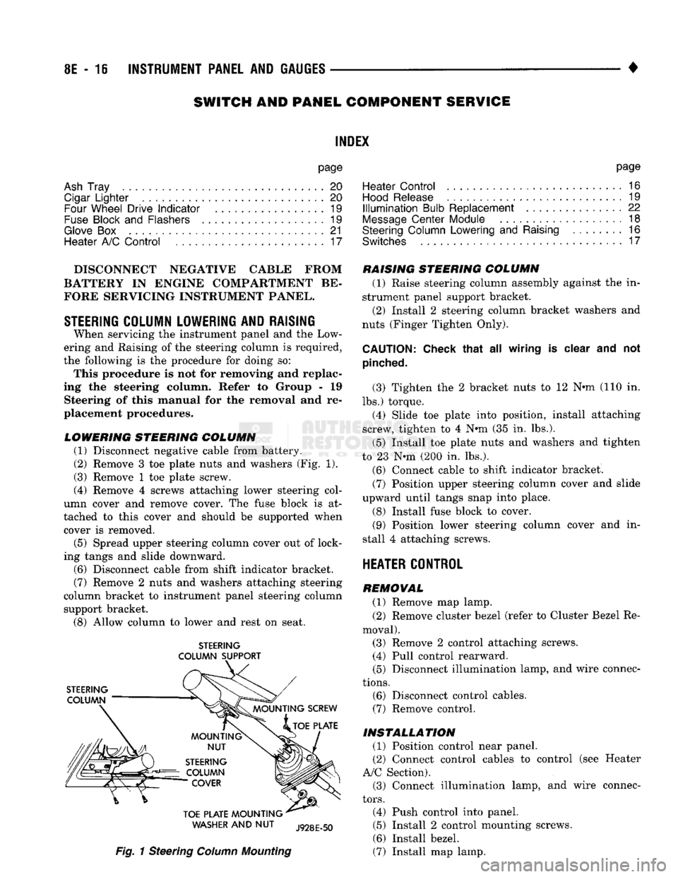
Remove 3 toe plate nuts and washers (Fig. 1).
(3) Remove 1 toe plate screw.
(4) Remove 4 screws attaching lower steering col
umn cover and remove cover. The fuse block is at
tached to this cover and should be supported when cover is removed.
(5) Spread upper steering column cover out of lock
ing tangs and slide downward.
(6)
Disconnect cable from shift indicator bracket.
(7)
Remove 2 nuts and washers attaching steering
column bracket to instrument panel steering column support bracket.
(8)
Allow column to lower and rest on seat.
STEERING
COLUMN SUPPORT
WASHER
AND NUT
Fig.
1 Steering
Column
Mounting
RAISING STEERING COLUMN
(1) Raise steering column assembly against the in
strument panel support bracket. (2) Install 2 steering column bracket washers and
nuts (Finger Tighten Only).
CAUTION:
Check that
all
wiring
is
clear
and not
pinched.
(3) Tighten the 2 bracket nuts to 12 Nnn-(110 in.
lbs.) torque. (4) Slide toe plate into position, install attaching
screw, tighten to 4 N®m (35 in. lbs.).
(5) Install toe plate nuts and washers and tighten
to 23 N*m (200 in. lbs.).
(6)
Connect cable to shift indicator bracket.
(7)
Position upper steering column cover and slide
upward until tangs snap into place.
(8) Install fuse block to cover.
(9)
Position lower steering column cover and in
stall 4 attaching screws.
HEATER CONTROL
REMOVAL
(1) Remove map lamp.
(2) Remove cluster bezel (refer to Cluster Bezel Re
moval). (3) Remove 2 control attaching screws. (4) Pull control rearward.
(5) Disconnect illumination lamp, and wire connec
tions.
(6)
Disconnect control cables.
(7)
Remove control.
INSTALLATION
(1) Position control near panel.
(2) Connect control cables to control (see Heater
A/C Section). (3) Connect illumination lamp, and wire connec
tors.
(4) Push control into panel.
(5) Install 2 control mounting screws.
(6)
Install bezel.
(7)
Install map lamp.
Page 398 of 1502
INSTRUMENT
PANEL
AND
GAUGES
8E - 17
HEATER
A/C
CONTROL
REMOVAL
(1) Remove map lamp.
(2) Remove cluster bezel (refer to Cluster Bezel Re
moval).
(3) Remove 2 control attaching screws.
(4) Pull control rearward.
(5) Disconnect blower switch wiring.
(6) Disconnect wires to pushbutton switch (three
connectors). (7) Disconnect illumination lamp.
(8) Disconnect vacuum harness.
(9) Disconnect temperature cable.
(10) Remove control.
INSTALLATION
(1) Position control near panel.
(2) Connect temperature cable (see Group 24 -
Heating and Air Conditioning).
(3) Connect vacuum harness. (4) Connect illumination lamp.
(5) Attach 3 wire connectors to pushbutton switch.
(6) Connect wires to blower motor switch.
(7) Push control into panel.
(8) Install 2 control mounting screws.
(9) Install cluster bezel.
(10) Install map lamp.
INSTRUMENT
PANEL SWITCHES
HEADLAMP
SWITCH
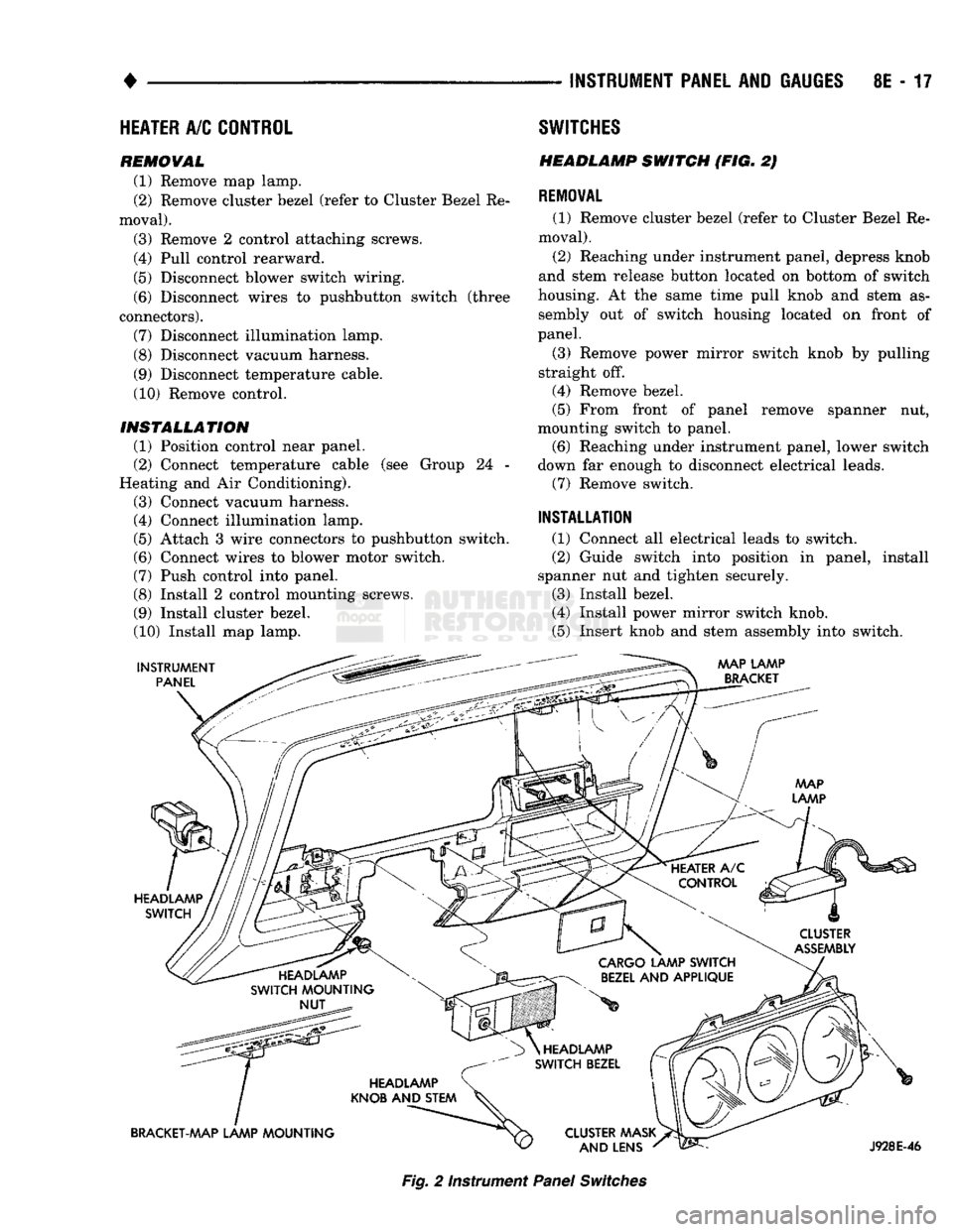
(FIG. 2)
REMOVAL
(1) Remove cluster bezel (refer to Cluster Bezel Re
moval).
(2) Reaching under instrument panel, depress knob
and stem release button located on bottom of switch
housing. At the same time pull knob and stem as sembly out of switch housing located on front of
panel.
(3) Remove power mirror switch knob by pulling
straight off.
(4) Remove bezel.
(5) From front of panel remove spanner nut,
mounting switch to panel. (6) Reaching under instrument panel, lower switch
down far enough to disconnect electrical leads. (7) Remove switch.
INSTALLATION
(1) Connect all electrical leads to switch.
(2) Guide switch into position in panel, install
spanner nut and tighten securely.
(3) Install bezel.
(4) Install power mirror switch knob.
(5) Insert knob and stem assembly into switch.
AAAP LAMP
BRACKET
HEADLAMP SWITCH
CLUSTER
ASSEMBLY
HEADLAMP
SWITCH MOUNTING NUT
CARGO
LAMP SWITCH
BEZEL
AND APPLIQUE
HEADLAMP
KNOB AND STEM
BRACKET-MAP LAMP MOUNTING HEADLAMP
SWITCH BEZEL
CLUSTER AAASK AND LENS
J928E-46
Fig.
2 Instrument
Panel
Switches
Page 399 of 1502
8E
- 18
INSTRUMENT PANEL
AND
GAUGES
—
•
Fig.
3 Overdrive
Lockout
Switch
and
Message
Center
Module
J918E-32
Fig.
4
Message
Center Printed Circuit
Board—Automatic
Transmission
INSTALLATION
(1) Position lockout switch into module and push
until retaining tabs lock into place.
(2) Connect switch connector.
(3)
Install instrument cluster bezel to panel.
MESSAGE
CENTER MODULE
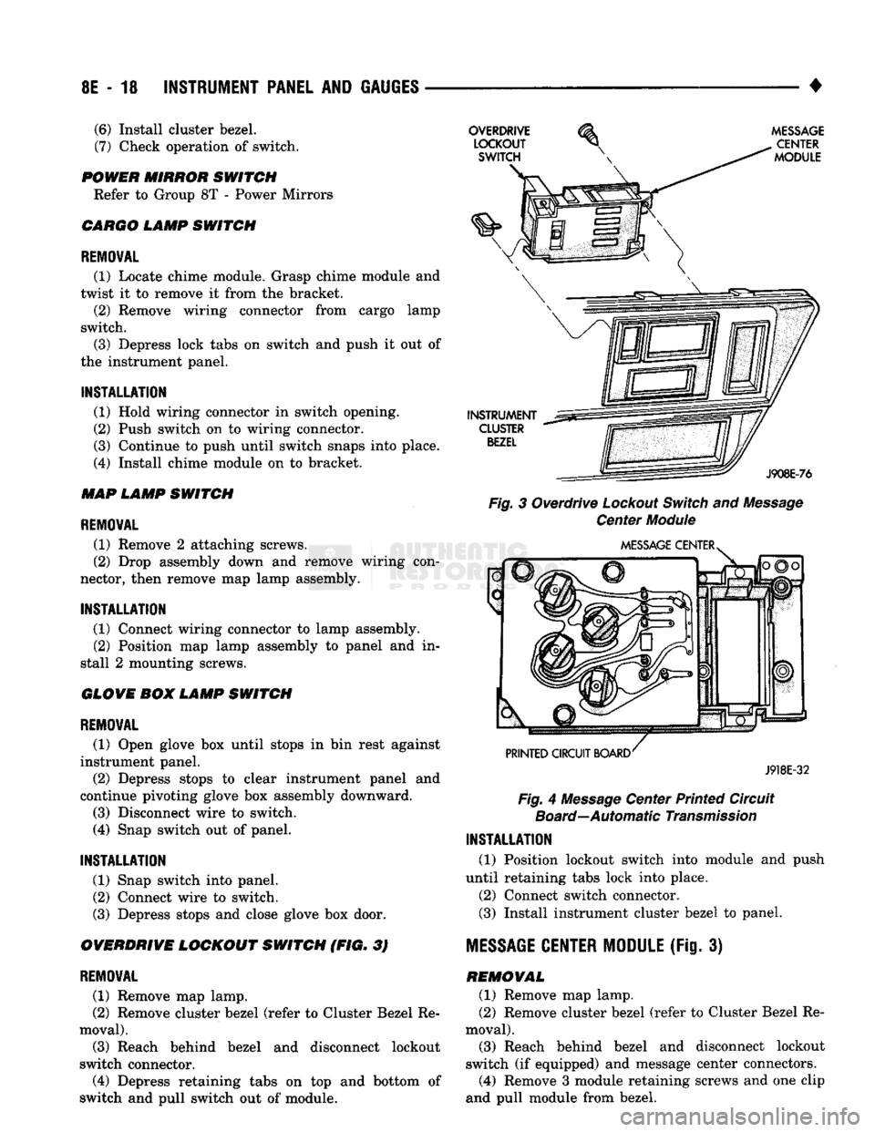
(Fig. 3) REMOVAL (1) Remove map lamp.
(2) Remove cluster bezel (refer to Cluster Bezel Re
moval).
(3)
Reach behind bezel and disconnect lockout
switch (if equipped) and message center connectors.
(4)
Remove 3 module retaining screws and one clip
and pull module from bezel.
(6)
Install cluster bezel.
(7)
Check operation of switch.
POWER MIRROR SWITCH Refer to Group 8T - Power Mirrors
CARGO LAMP SWITCH
REMOVAL
(1) Locate chime module. Grasp chime module and
twist it to remove it from the bracket. (2) Remove wiring connector from cargo lamp
switch.
(3)
Depress lock tabs on switch and push it out of
the instrument panel.
INSTALLATION
(1) Hold wiring connector in switch opening.
(2) Push switch on to wiring connector.
(3)
Continue to push until switch snaps into place.
(4)
Install chime module on to bracket.
MAP LAMP SWITCH
REMOVAL
(1) Remove 2 attaching screws.
(2) Drop assembly down and remove wiring con
nector, then remove map lamp assembly.
INSTALLATION
(1) Connect wiring connector to lamp assembly. (2) Position map lamp assembly to panel and in
stall 2 mounting screws.
GLOVE BOX LAMP SWITCH
REMOVAL
(1) Open glove box until stops in bin rest against
instrument panel.
(2) Depress stops to clear instrument panel and
continue pivoting glove box assembly downward.
(3)
Disconnect wire to switch.
(4)
Snap switch out of panel.
INSTALLATION
(1) Snap switch into panel.
(2) Connect wire to switch.
(3)
Depress stops and close glove box door.
OVERDRIVE LOCKOUT SWITCH (FIG. 3)
REMOVAL
(1) Remove map lamp.
(2) Remove cluster bezel (refer to Cluster Bezel Re
moval).
(3)
Reach behind bezel and disconnect lockout
switch connector.
(4)
Depress retaining tabs on top and bottom of
switch and pull switch out of module.
Page 400 of 1502
•
INSTRUMENT PANEL
AND
GAUGES
8E - 19
MESSAGE
CENTER
PRINTED CIRCUIT BOARD
J918E-33
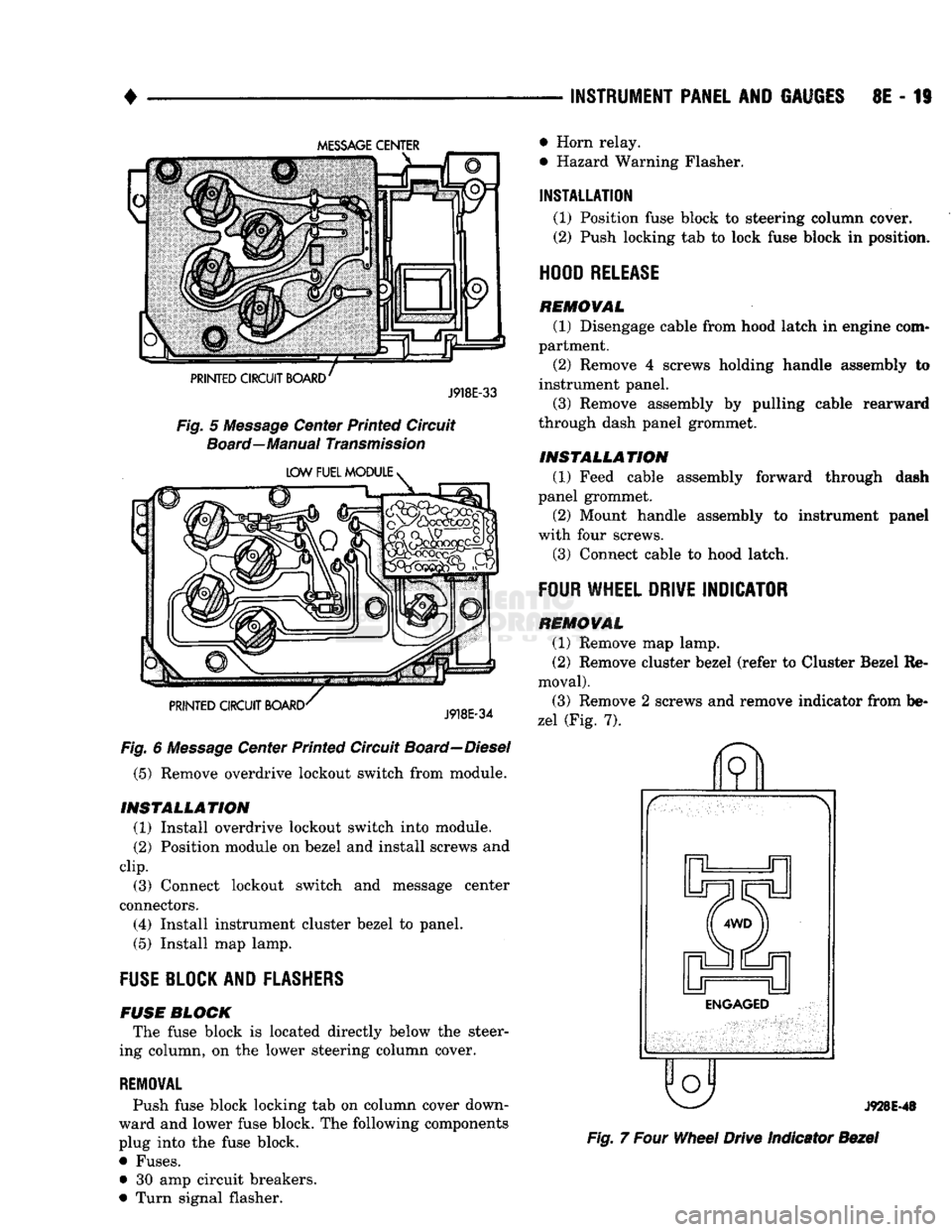
Fig.
5
Message
Center Printed Circuit
Board—Manual
Transmission
LOW FUEL MODULE
>
PRINTED CIRCUIT BOARD
J918E-34
Fig.
6
Message
Center Printed Circuit
Board—Diesel
(5) Remove overdrive lockout switch from module.
INSTALLATION
(1) Install overdrive lockout switch into module.
(2) Position module on bezel and install screws and
clip.
(3) Connect lockout switch and message center
connectors.
(4) Install instrument cluster bezel to panel.
(5) Install map lamp.
FUSE
BLOCK AND
FLASHERS
FUSE
BLOCK
The fuse block is located directly below the steer
ing column, on the lower steering column cover.
REMOVAL
Push fuse block locking tab on column cover down
ward and lower fuse block. The following components
plug into the fuse block.
• Fuses. • 30 amp circuit breakers.
• Turn signal flasher. • Horn relay.
• Hazard Warning Flasher.
INSTALLATION
(1) Position fuse block to steering column cover. (2) Push locking tab to lock fuse block in position.
HOOD
RELEASE
REMOVAL
(1) Disengage cable from hood latch in engine com
partment. (2) Remove 4 screws holding handle assembly to
instrument panel.
(3) Remove assembly by pulling cable rearward
through dash panel grommet.
INSTALLATION
(1) Feed cable assembly forward through dash
panel grommet.
(2) Mount handle assembly to instrument panel
with four screws.
(3) Connect cable to hood latch.
FOUR
WHEEL
DRIVE
INDICATOR
REMOVAL
(1) Remove map lamp.
(2) Remove cluster bezel (refer to Cluster Bezel Re
moval).
(3) Remove 2 screws and remove indicator from be
zel (Fig. 7).
o
J928E-48
Fig.
7
Four
Wheel
Drive Indicator
Bezel
Page 401 of 1502
8E
- 20
INSTRUMENT PANEL
AND
GAUGES
•
INSTALLATION
(1) Position indicator to bezel and attach with two
screws. (2) Install cluster bezel.
(3) Install map lamp.
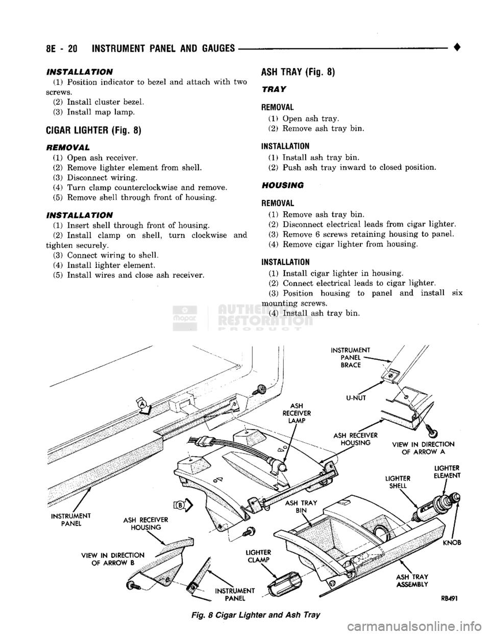
CIGAR LIGHTER
(Fig. 8) REMOVAL (1) Open ash receiver.
(2) Remove lighter element from shell.
(3) Disconnect wiring.
(4) Turn clamp counterclockwise and remove.
(5) Remove shell through front of housing.
INSTALLATION
(1) Insert shell through front of housing.
(2) Install clamp on shell, turn clockwise and
tighten securely.
(3) Connect wiring to shell.
(4) Install lighter element.
(5) Install wires and close ash receiver.
ASH
TRAY
(Fig. 8)
TRAY
REMOVAL
(1) Open ash tray.
(2) Remove ash tray bin.
INSTALLATION
(1) Install ash tray bin.
(2) Push ash tray inward to closed position.
HOUSING
REMOVAL
(1) Remove ash tray bin. (2) Disconnect electrical leads from cigar lighter.
(3) Remove 6 screws retaining housing to panel.
(4) Remove cigar lighter from housing.
INSTALLATION
(1) Install cigar lighter in housing.
(2) Connect electrical leads to cigar lighter. (3) Position housing to panel and install six
mounting screws.
(4) Install ash tray bin. Fig. 8
Cigar
Lighter and Ash
Tray
Page 403 of 1502
8E
- 22
INSTRUMENT PANEL
AND
GAUGES
•
ILLUMINATION BULB
REPLACEMENT
ASH
TRAY ILLUMINATION LAMP
REMOVAL
(1) Open ash receiver and remove bin.
(2)
Disconnect wires from cigar lighter.
(3)
Remove 6 screws that retain assembly to panel.
(4)
While dropping ash receiver, remove lamp as
sembly from top of the housing.
INSTALLATION
(1) Install lamp assembly into top of housing.
(2)
Position housing and install 6 mounting
screws.
(3)
Connect wires to cigar lighter.
(4)
Install bin and close ash receiver.
MAP
LAMP BULB
To replace bulb, snap lens out, replace bulb.
FOUR
WHEEL DRIVE INDICATOR
REMOVAL
(1) Remove map lamp.
(2)
Remove cluster bezel (refer to Cluster Bezel Re
moval).
(3)
Remove bulb and socket.
INSTALLATION
(1) Snap in bulb and socket.
(2)
Replace cluster bezel.
(3)
Install map lamp.
HEATER
OR
HEATER
A/C
ILLUMINATION
LAMP
REMOVAL
(1) Remove map lamp.
(2)
Remove cluster bezel (refer to Cluster Bezel Re
moval).
(3)
Remove two control attaching screws.
(4)
Pull control rearward.
(5) Snap out illumination lamp.
INSTALLATION
(1) Install bulb into socket.
(2)
Snap socket into control.
(3)
Push control forward and install two attaching
screws.
(4)
Install cluster bezel. (5) Install map lamp.
Page 410 of 1502
•
AUDIO
SYSTEMS
8F - 7
SERVICE
PROCEDURES
RADIO
REPLACEMENT
REMOVAL
(1) Disconnect negative cable from battery.
CAUTION:
Map
lamp
must
be
removed
to
prevent
damage
to instrument panel.
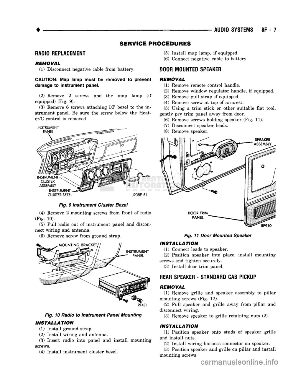
(2) Remove 2 screws and the map lamp (if
equipped) (Fig. 9). (3) Remove 6 screws attaching I/P bezel to the in
strument panel. Be sure the screw below the Heat-
er/C control is removed.
CLUSTER
BEZEL
J938E-51
Fig.
9 Instrument
Cluster
Bezel
(4) Remove 2 mounting screws from front of radio
(Fig. 10).
(5) Pull radio out of instrument panel and discon
nect wiring and antenna.
(6)
Remove screw from ground strap.
RF431
Fig.
10 Radio to Instrument
Panel
Mounting
INSTALLATION
(1) Install ground strap.
(2) Install wiring and antenna. (3) Insert radio into panel and install mounting
screws.
(4) Install instrument cluster bezel.
(5)
Install map lamp, if equipped.
(6) Connect negative cable to battery.
DOOR
MOUNTED
SPEAKER
REMOVAL
(1) Remove remote control handle.
(2) Remove window regulator handle, if equipped.
(3) Remove pull strap if equipped.
(4) Remove screw at top of armrest.
(5)
Using a trim stick or other suitable flat tool,
gently pry trim panel away from door.
(6) Remove screws holding speaker (Fig. 11).
(7) Disconnect speaker leads.
(8) Remove speaker.
Fig.
11
Door
Mounted
Speaker
INSTALLATION
(1) Connect leads to speaker.
(2) Position speaker into place, install mounting
screws and tighten securely.
(3) Install door trim panel.
REAR
SPEAKER
-
STANDARD
CAB PICKUP
REMOVAL
(1) Remove grille and speaker assembly to pillar
mounting screws (Fig. 12). (2) Pull speaker and grille away from pillar and
disconnect wiring.
(3) Remove speaker to grille retaining nuts (2).
INSTALLATION
(1) Position speaker onto studs of speaker grille
and install nuts.
(2) Install wiring harness connector on speaker.
(3) Position speaker and grille on pillar and install
mounting screws.