1993 DODGE TRUCK ignition
[x] Cancel search: ignitionPage 863 of 1502
14 - 44
FUEL
SYSTEM
•
Fig.
4 ignition Coil—5.9L
HDC-Gas
Engine
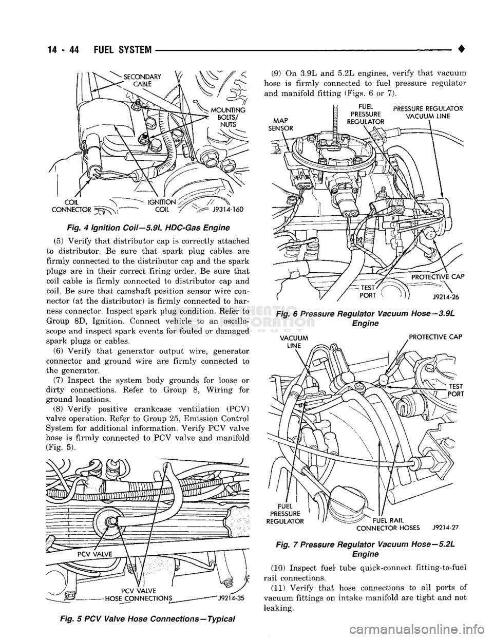
(5) Verify that distributor cap is correctly attached
to distributor. Be sure that spark plug cables are
firmly connected to the distributor cap and the spark
plugs are in their correct firing order. Be sure that coil cable is firmly connected to distributor cap and
coil. Be sure that camshaft position sensor wire con
nector (at the distributor) is firmly connected to har
ness connector. Inspect spark plug condition. Refer to Group 8D, Ignition. Connect vehicle to an oscillo
scope and inspect spark events for fouled or damaged
spark plugs or cables.
(6) Verify that generator output wire, generator
connector and ground wire are firmly connected to
the generator. (7) Inspect the system body grounds for loose or
dirty connections. Refer to Group 8, Wiring for
ground locations. (8) Verify positive crankcase ventilation (PCV)
valve operation. Refer to Group 25, Emission Control System for additional information. Verify PCV valve
hose is firmly connected to PCV valve and manifold (Fig. 5).
Fig.
5 PCV
Valve
Hose
Connections—Typical (9) On 3.9L and 5.2L engines, verify that vacuum
hose is firmly connected to fuel pressure regulator and manifold fitting (Figs. 6 or 7).
CONNECTOR
HOSES
J9214-27
Fig.
7
Pressure
Regulator
Vacuum
Hose—5.2L
Engine
(10) Inspect fuel* tube quick-connect fitting-to-fuel
rail connections. (11) Verify that hose connections to all ports of
vacuum fittings on intake manifold are tight and not leaking.
Page 867 of 1502
CAV
WIRE
COLOR DESCRIPTION
CAV
WIRE
COLOR DESCRIPTION
1 DG/RD*
MAP SENSOR 37
BK/OR OVERDRIVE LAMP
2 TN/BK*
ENGINE COOLANT TEMPERATURE SENSOR 38 PK/BK INJECTOR DRIVE
#5
3 RD/WT DIRECT BATTERY 39 GY/RD IAC MOTOR
#4
4
BK/LB*
SENSOR RETURN 40 BR/WT
IAC MOTOR
#2
5 BK/WT SIGNAL GROUND 41
BK/DG* OXYGEN SENSOR SIGNAL
6 VT/WT
5-VOLT
OUTPUT
(MAP AND TPS)
42
7 OR
8-VOLT
OUTPUT (DISTRIBUTOR PICK-UP) 43
GY/LB*
TACHOMETER SIGNAL OUTPUT (VEHICLES W/TACHOMETER)
8 44 GY CAMSHAFT POSITION SENSE
9 DB
J2-IGNITION FEED 45
LG SCI RECIEVE
10 R/WT OVERDRIVE OVERRIDE
46 CCD
(-)
11 BK/TN POWER GROUND 47 WT/OR* SPEED SENSOR SIGNAL
12 BK/TN POWER GROUND 48 BR/RD* SPEED CONTROL
SET
SWITCH
13 LB/BR
INJECTOR DRIVER
#4
49
YL/RD* SPEED CONTROL ON/OFF SWITCH
14 YL/WT
INJECTOR DRIVER
#3
50 WT/LG* SPEED CONTROL RESUME SWITCH
15 TN INJECTOR DRIVER
#2
51 DB/YL*
AUTO SHUTDOWN
(ASD)
RELAY
-
RETURN
16
WT/DB*
INJECTOR DRIVER
#1
52 PK/BK
EVAP CANISTER PURGE SOLENOID
17 DB/TN INJECTOR DRIVER
#7
(V-8
ONLY) 53 LG/RD* SPEED CONTROL VENT SOLENOID
18 DB/GY
INJECTOR DRIVER
#8
(V-8
ONLY) 54
OR/BK* SHIFT INDICATOR LIGHT (MANUAL TRANSMISSION ONLY)
19 BK/GY*
IGNITION COIL DRIVER 54
OR/BK* CONVERTOR CLUTCH SOLENOID (AUTO TRANSMISSION)
20 DG
GENERATOR FIELD CONTROL 55
OR/WT OVERDRIVE SOLENOID (AUTO TRANSMISSION ONLY)
21 BK/RD
CHARGE TEMPERATURE SENSOR 56
GY/PK SRI LAMP
(5.9L HDC
ENGINE)
22
OR/DB*
THROTTLE POSITION SENSOR
(TPS)
57
DG/OR ASD SENSE
23 TN/WT
OXYGEN SENSOR SIGNAL
(5.9L HDC
ENGINE) 58 LG/BK
INJECTOR DRIVER
#6
24 GY/BK IGNITION (CAMSHAFT POSITION SENSOR) 59
VT/BK IAC MOTOR
#1
25 PK
,
SCI
TRANSMIT 60
YL/BK* IAC MOTOR
#3
26 CCD
(-:-)
WIRE COLOR CODES LB
LIGHT BLUE
VT VIOLET
27 BR
A/C SWITCH SENSE BK BLACK
LG LIGHT GREEN
WT
WHITE
28 VT A/C SELECT BR BROWN
OR ORANGE
YL YELLOW
29 WT/PK* BRAKE SWITCH
-
DB DARK BLUE PK
PINK *
WITH TRACER
30 BY/YL*
PARK/NEUTRAL SWITCH DG DARK GREEN
RD
RED
31 GY
GRAY TN TAN
32 BK/PK*
MALFUNCTION INDICATOR LAMP
33 TN/RD*
SPEED CONTROL VACUUM SOLENOID CONNECTOR
34 DB/OR* A/C CLUTCH RELAY TERMINAL
|(pcKX>coooop0ffoj'
oooooooooojj
35 GY/YL*
EGR SOLENOID SHOWN W'41
30
50«M#5l31
604
%\
oooooooooo ••ooooooooooj
36 J9314-171
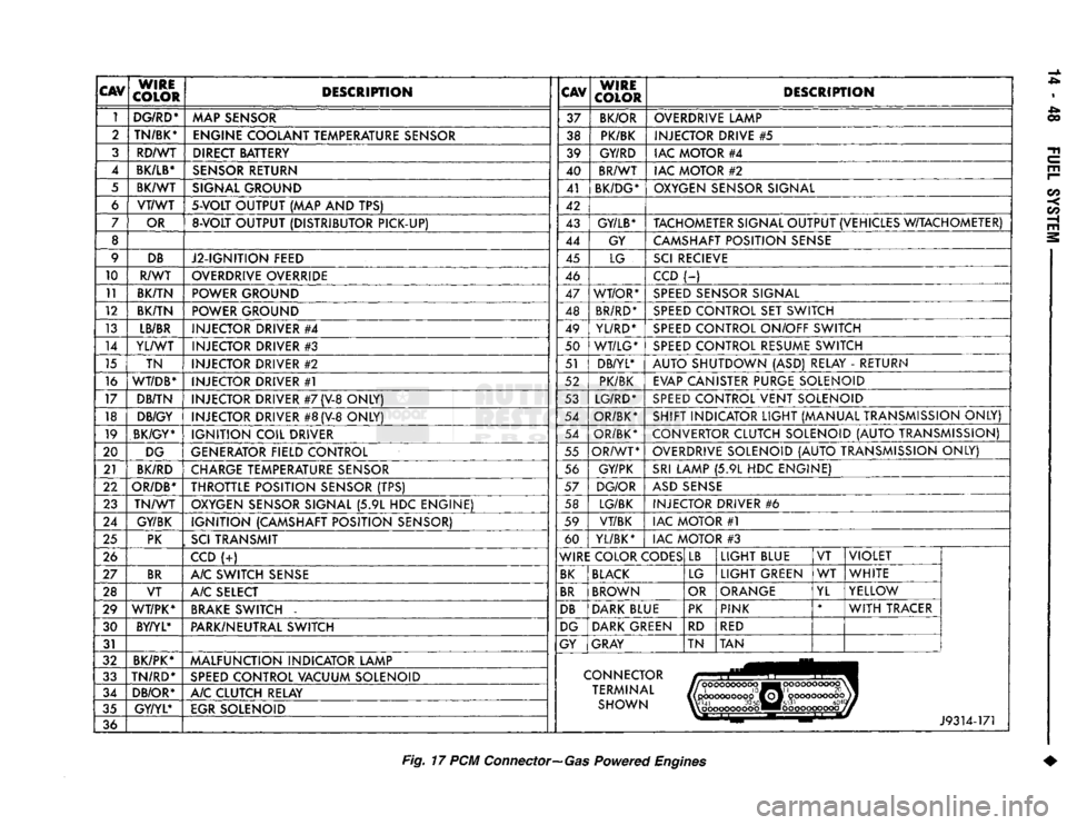
Fig.
17 PCM
Connector—Gas
Powered
Engines
Page 871 of 1502
14-52
FUEL
SYSTEM
•
CAMSHAFT
POSITION
SENSOR
TESTING
Refer to Group 8D, Ignition Systems for testing.
COOLANT
TEMPERATURE
SENSOR
TEST
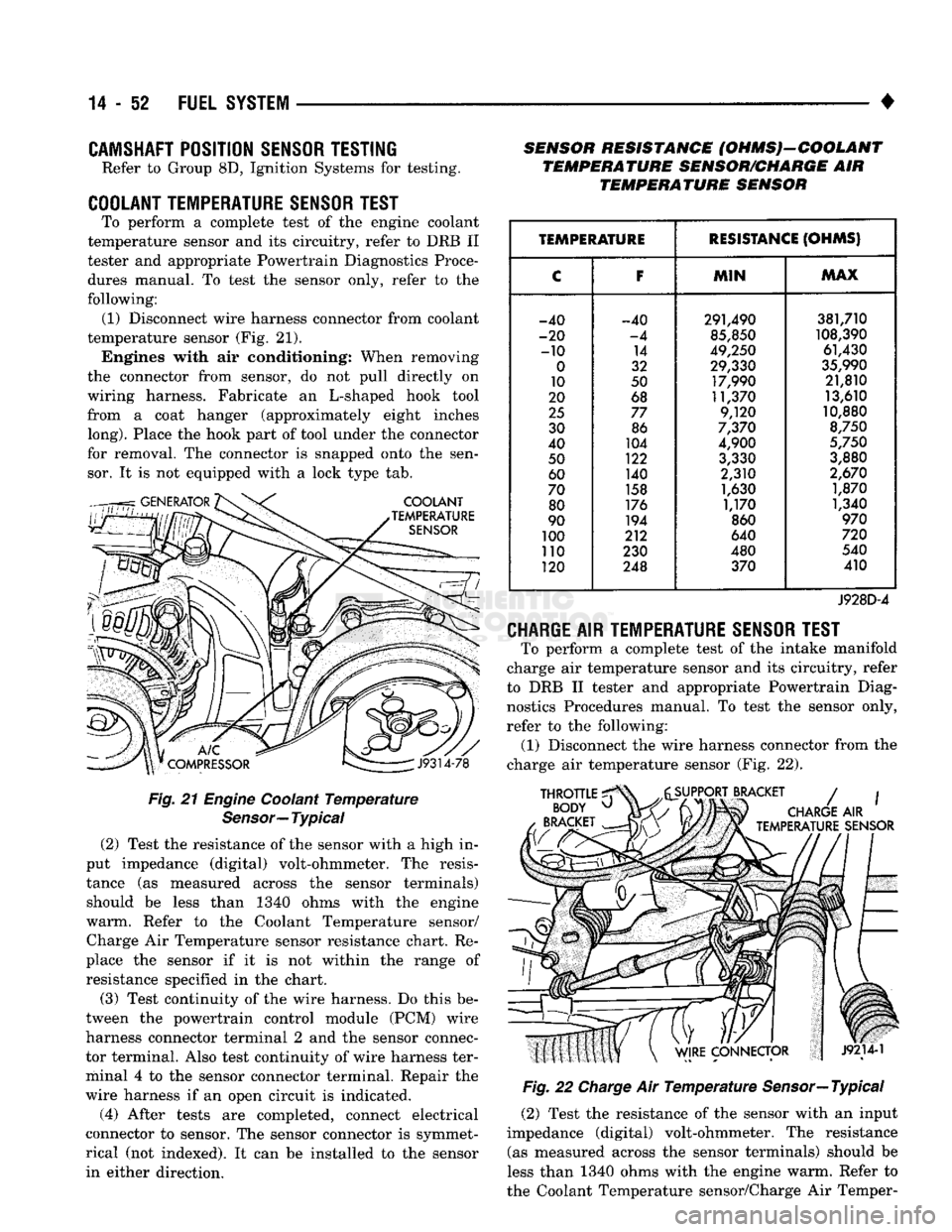
To perform a complete test of the engine coolant
temperature sensor and its circuitry, refer to DRB II
tester and appropriate Powertrain Diagnostics Proce
dures manual. To test the sensor only, refer to the
following: (1) Disconnect wire harness connector from coolant
temperature sensor (Fig. 21). Engines with air conditioning; When removing
the connector from sensor, do not pull directly on
wiring harness. Fabricate an L-shaped hook tool
from a coat hanger (approximately eight inches
long).
Place the hook part of tool under the connector
for removal. The connector is snapped onto the sen sor. It is not equipped with a lock type tab.
Fig.
21
Engine
Coolant
Temperature
Sensor—
Typical
(2) Test the resistance of the sensor with a high in
put impedance (digital) volt-ohmmeter. The resis
tance (as measured across the sensor terminals) should be less than 1340 ohms with the engine
warm. Refer to the Coolant Temperature sensor/ Charge Air Temperature sensor resistance chart. Re
place the sensor if it is not within the range of resistance specified in the chart.
(3) Test continuity of the wire harness. Do this be
tween the powertrain control module (PCM) wire
harness connector terminal 2 and the sensor connec
tor terminal. Also test continuity of wire harness ter
minal 4 to the sensor connector terminal. Repair the
wire harness if an open circuit is indicated.
(4) After tests are completed, connect electrical
connector to sensor. The sensor connector is symmet
rical (not indexed). It can be installed to the sensor in either direction. SENSOR RESISTANCE (OHMS)-COOLANT
TEMPERATURE SENSOR/CHARGE AIR TEMPERATURE SENSOR
TEMPERATURE
RESISTANCE
(OHMS)
C F
MIN MAX
-40 -40 291,490 381,710
-20 -4 85,850 108,390
-10 14 49,250 61,430
0 32 29,330 35,990
10 50 17,990 21,810
20 68 11,370 13,610
25 77 9,120 10,880
30 86 7,370 8,750
40 104 4,900 5,750
50 122 3,330 3,880
60 140 2,310 2,670
70 158 1,630 1,870
80 176 1,170 1,340
90 194 860 970
100 212 640 720
no 230 480 540
120 248 370 410
J928D-4
CHARGE
AIR
TEMPERATURE SENSOR TEST
To perform a complete test of the intake manifold
charge air temperature sensor and its circuitry, refer
to DRB II tester and appropriate Powertrain Diag nostics Procedures manual. To test the sensor only,
refer to the following: (1) Disconnect the wire harness connector from the
charge air temperature sensor (Fig. 22).
Fig.
22
Charge
Air
Temperature
Sensor—Typical
(2) Test the resistance of the sensor with an input
impedance (digital) volt-ohmmeter. The resistance (as measured across the sensor terminals) should be
less than 1340 ohms with the engine warm. Refer to
the Coolant Temperature sensor/Charge Air Temper-
Page 872 of 1502
•
FUEL
SYSTEM
14-53 ature sensor resistance chart. Replace the sensor if it
is not within the range of resistance specified in the chart. (3) Test the resistance of the wire harness. Do this
between the powertrain control module (PCM) wire
harness connector terminal 21 and the sensor connec tor terminal. Also check between terminal 4 to the sensor connector terminal. Repair the wire harness
as necessary if the resistance is greater than 1 ohm.
MANIFOLD
ABSOLUTE
PRESSURE
(MAP)
SENSOR
TEST
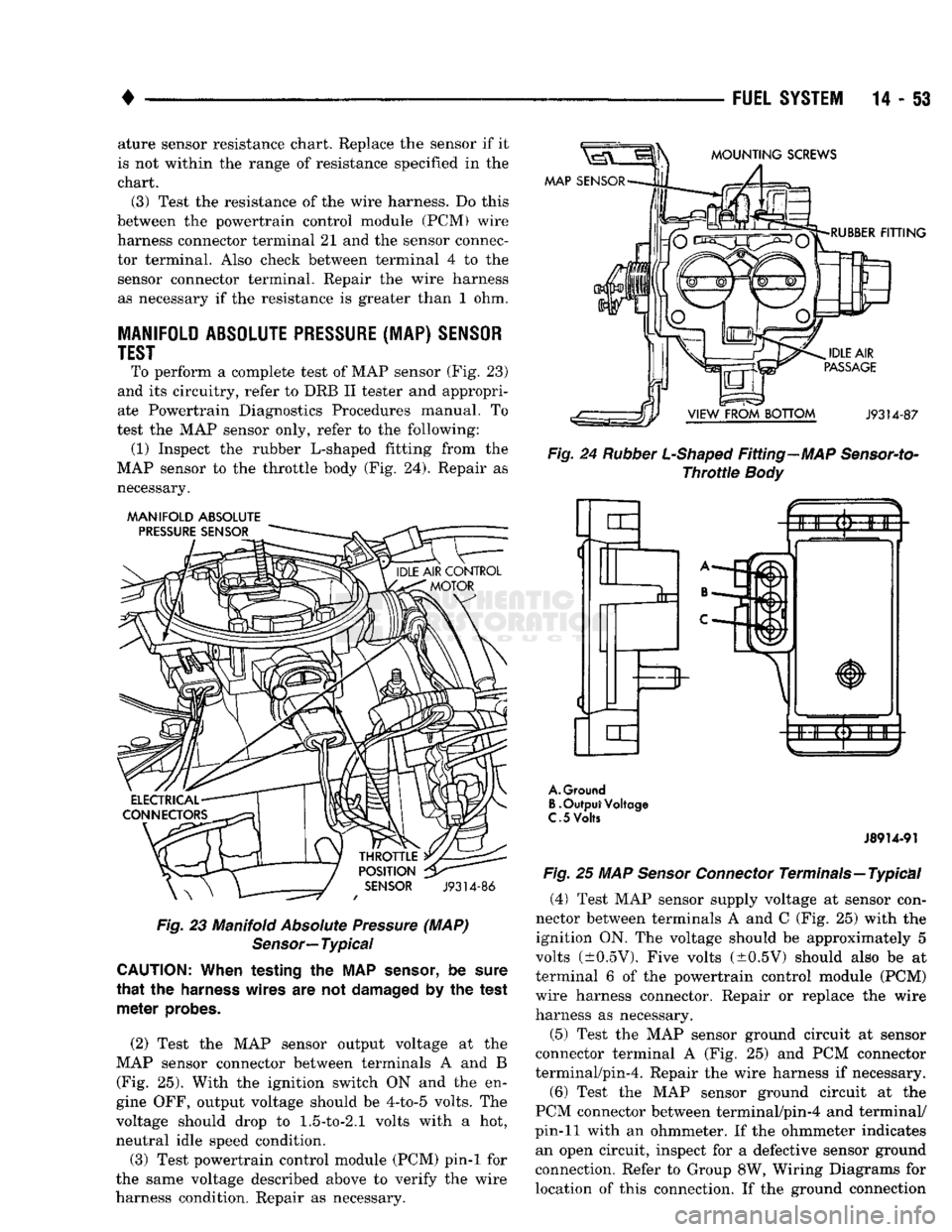
To perform a complete test of MAP sensor (Fig. 23)
and its circuitry, refer to DRB II tester and appropri
ate Powertrain Diagnostics Procedures manual. To
test the MAP sensor only, refer to the following: (1) Inspect the rubber L-shaped fitting from the
MAP sensor to the throttle body (Fig. 24). Repair as necessary.
MANIFOLD
ABSOLUTE
Fig.
23 Manifold
Absolute
Pressure
(MAP)
Sensor—
Typical
CAUTION:
When testing the MAP
sensor,
be
sure
that
the
harness
wires are not
damaged
by the test
meter
probes.
(2) Test the MAP sensor output voltage at the
MAP sensor connector between terminals A and B (Fig. 25). With the ignition switch ON and the en
gine OFF, output voltage should be 4-to-5 volts. The
voltage should drop to
1.5-to-2.1
volts with a hot,
neutral idle speed condition.
(3) Test powertrain control module (PCM) pin-1 for
the same voltage described above to verify the wire
harness condition. Repair as necessary.
Fig.
24
Rubber
L-Shaped
Fitting—MAP
Sensor-to-
Throttle
Body
A.
Ground
B.
Output Voltage
C.
5
Volts
J8914-91
Fig.
25 MAP
Sensor
Connector
Terminals—Typical
(4)
Test MAP sensor supply voltage at sensor con
nector between terminals A and C (Fig. 25) with the ignition ON. The voltage should be approximately 5
volts (±0.5V). Five volts (±0.5V) should also be at
terminal 6 of the powertrain control module (PCM)
wire harness connector. Repair or replace the wire
harness as necessary.
(5) Test the MAP sensor ground circuit at sensor
connector terminal A (Fig. 25) and PCM connector
terminal/pin-4. Repair the wire harness if necessary.
(6) Test the MAP sensor ground circuit at the
PCM connector between terminal/pin-4 and terminal/
pin-11 with an ohmmeter. If the ohmmeter indicates an open circuit, inspect for a defective sensor ground
connection. Refer to Group 8W, Wiring Diagrams for
location of this connection. If the ground connection
Page 873 of 1502
14-54 FUEL SYSTEM
• is good, replace the PCM. If terminal/pin-4 has a
short circuit to 12 volts +, correct this condition be
fore replacing the PCM.
CRANKSHAFT POSITION SENSOR TEST
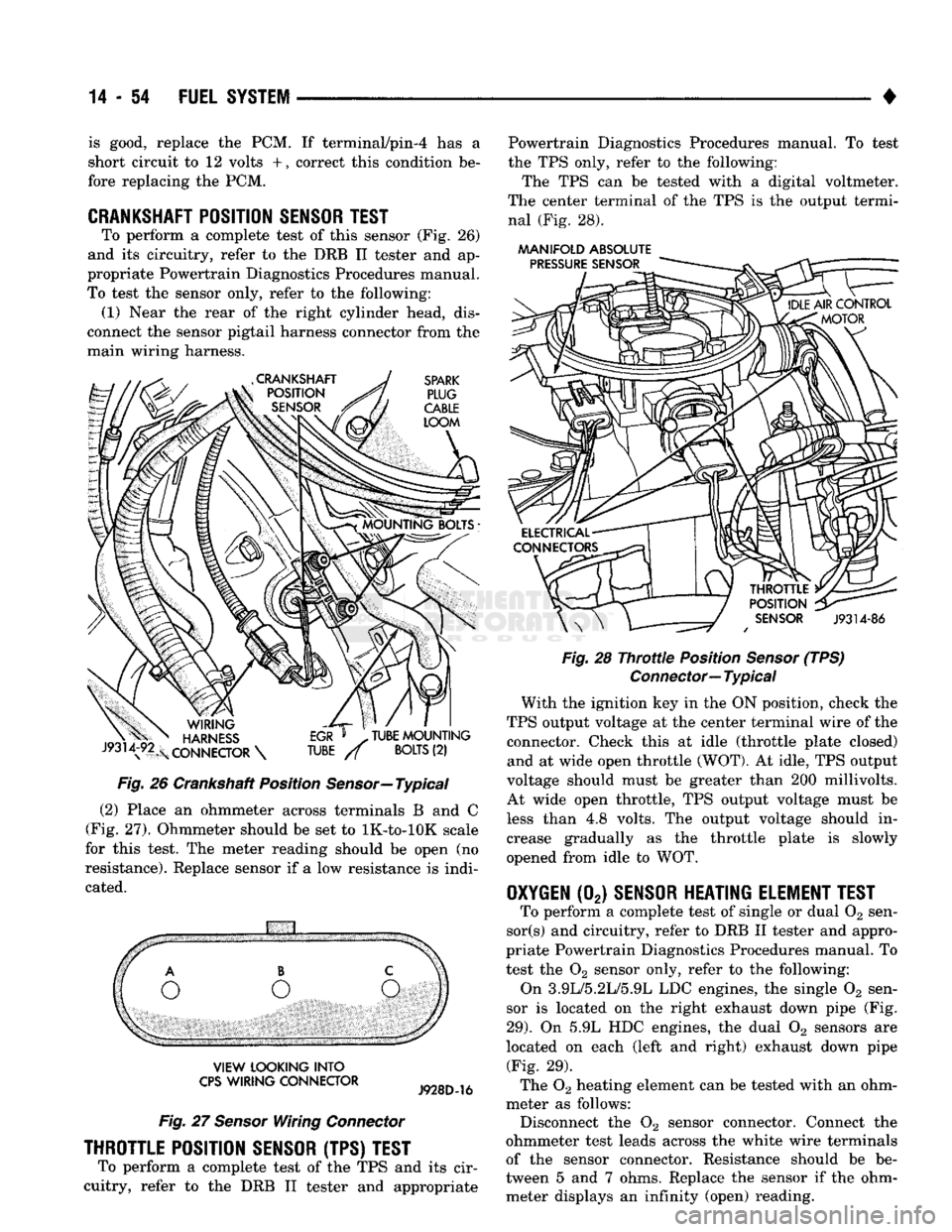
To perform a complete test of this sensor (Fig. 26)
and its circuitry, refer to the DRB II tester and ap
propriate Powertrain Diagnostics Procedures manual.
To test the sensor only, refer to the following: (1) Near the rear of the right cylinder head, dis
connect the sensor pigtail harness connector from the
main wiring harness.
Fig.
26 Crankshaft Position
Sensor—
Typical
(2) Place an ohmmeter across terminals B and C
(Fig. 27). Ohmmeter should be set to lK-to-lOK scale
for this test. The meter reading should be open (no
resistance). Replace sensor if a low resistance is indi
cated.
VIEW
LOOKING
INTO
CPS
WIRING
CONNECTOR
Fig.
27
Sensor
Wiring
Connector
THROTTLE POSITION SENSOR (TPS) TEST
To perform a complete test of the TPS and its cir
cuitry, refer to the DRB II tester and appropriate Powertrain Diagnostics Procedures manual. To test
the TPS only, refer to the following:
The TPS can be tested with a digital voltmeter.
The center terminal of the TPS is the output termi nal (Fig. 28).
AAANIFOLD
ABSOLUTE
Fig.
28
Throttle
Position
Sensor
(TPS)
Connector—
Typical
With the ignition key in the ON position, check the
TPS output voltage at the center terminal wire of the connector. Check this at idle (throttle plate closed) and at wide open throttle (WOT). At idle, TPS output
voltage should must be greater than 200 millivolts.
At wide open throttle, TPS output voltage must be
less than 4.8 volts. The output voltage should in
crease gradually as the throttle plate is slowly
opened from idle to WOT.
OXYGEN
(02)
SENSOR HEATING ELEMENT TEST
To perform a complete test of single or dual 02 sen-
sor(s) and circuitry, refer to DRB II tester and appro
priate Powertrain Diagnostics Procedures manual. To
test the 02 sensor only, refer to the following:
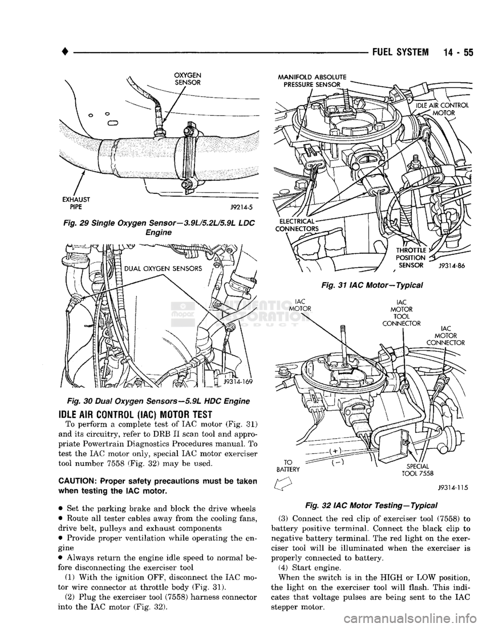
On 3.9L/5.2L/5.9L LDC engines, the single 02 sen
sor is located on the right exhaust down pipe (Fig.
29).
On 5.9L HDC engines, the dual 02 sensors are
located on each (left and right) exhaust down pipe (Fig. 29).
The 02 heating element can be tested with an ohm
meter as follows: Disconnect the 02 sensor connector. Connect the
ohmmeter test leads across the white wire terminals
of the sensor connector. Resistance should be be
tween 5 and 7 ohms. Replace the sensor if the ohm meter displays an infinity (open) reading.
Page 874 of 1502
•
FUEL
SYSTEM
14 - 55
Fig.
30
Dual
Oxygen
Sensors—5.9L
HDC
Engine
IDLE
AIR
CONTROL
(IAC)
MOTOR
TEST
To perform a complete test of IAC motor (Fig. 81)
and its circuitry, refer to DRB II scan tool and appro
priate Powertrain Diagnostics Procedures manual. To
test the IAC motor only, special IAC motor exerciser tool number 7558 (Fig. 32) may be used.
CAUTION:
Proper safety precautions must be
taken
when
testing
the IAC
motor,
• Set the parking brake and block the drive wheels
• Route all tester cables away from the cooling fans,
drive belt, pulleys and exhaust components
• Provide proper ventilation while operating the en
gine
• Always return the engine idle speed to normal be
fore disconnecting the exerciser tool
(1) With the ignition OFF, disconnect the IAC mo
tor wire connector at throttle body (Fig. 31).
(2) Plug the exerciser tool (7558) harness connector
into the IAC motor (Fig. 32).
MANIFOLD
ABSOLUTE
Fig.
31 IAC Motor—Typical
Fig.
32 IAC Motor
Testing—
Typical
(3) Connect the red clip of exerciser tool (7558) to
battery positive terminal. Connect the black clip to
negative battery terminal. The red light on the exer
ciser tool will be illuminated when the exerciser is
properly connected to battery. (4) Start engine.
When the switch is in the HIGH or LOW position,
the light on the exerciser tool will flash. This indi cates that voltage pulses are being sent to the IAC
stepper motor.
Page 875 of 1502
14
- 56
FUEL
SYSTEM
• (5) Move the switch to the HIGH position. The en
gine speed should increase. Move the switch to the
LOW position. The engine speed should decrease.
(a) If the engine speed changes while using the
exerciser tool, the IAC motor is functioning prop
erly. Disconnect the exerciser tool and connect the
IAC stepper motor wire connector to the stepper motor.
(b) If the engine speed does not change, turn the
ignition OFF and proceed to step (6). Do not discon
nect exerciser from the IAC stepper motor.
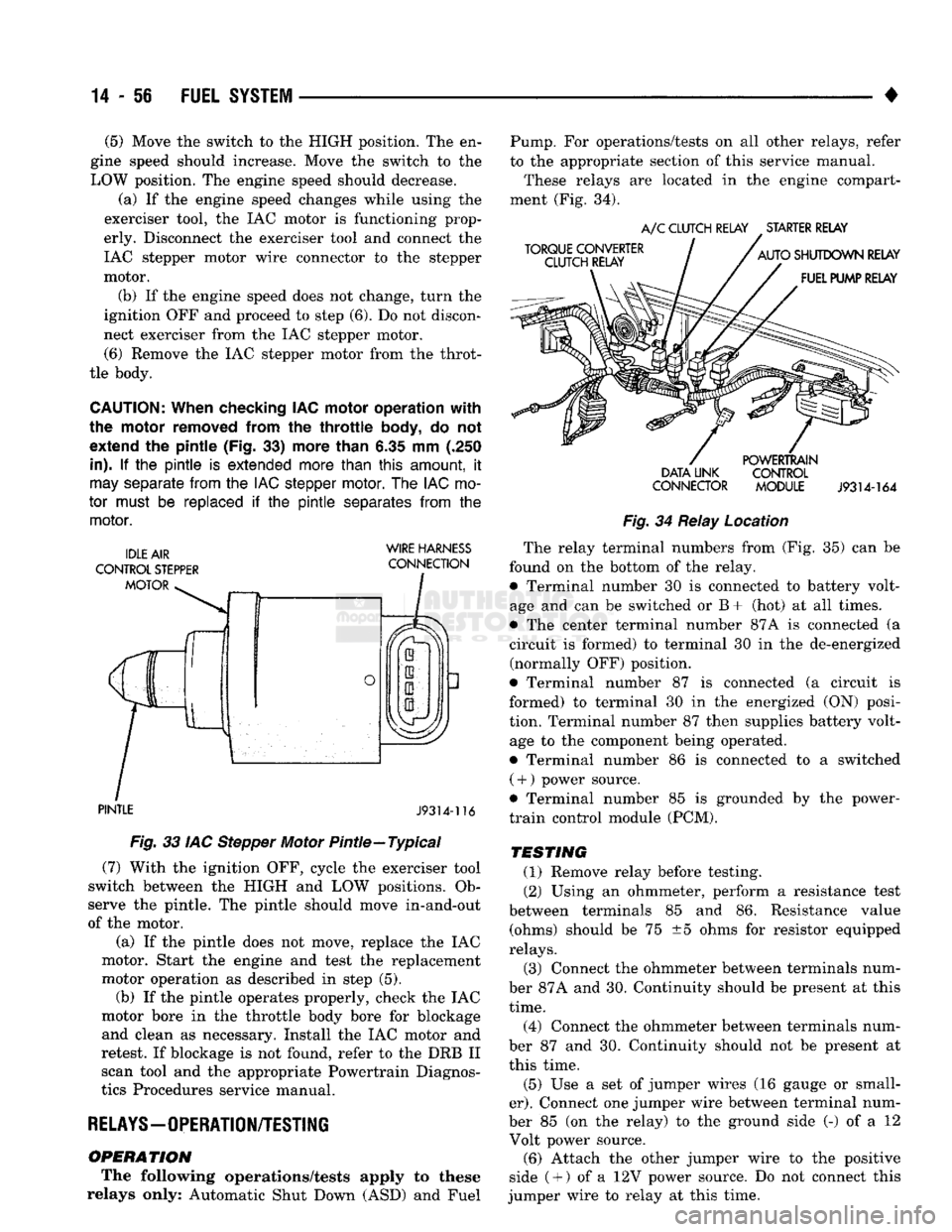
(6) Remove the IAC stepper motor from the throt
tle body.
CAUTION:
When checking IAC motor operation with
the motor removed from
the
throttle
body,
do not
extend
the
pintle (Fig.
33)
more than
6.35 mm (.250
in).
If the pintle is
extended more than
this
amount,
it
may
separate
from
the
IAC stepper
motor.
The
IAC
mo
tor
must
be
replaced
if the pintle
separates
from
the
motor.
WIRE HARNESS
PINTLE
J9314-116
Fig.
33 IAC Stepper Motor Pintle—Typical (7) With the ignition OFF, cycle the exerciser tool
switch between the HIGH and LOW positions. Ob
serve the pintle. The pintle should move in-and-out
of the motor.
(a) If the pintle does not move, replace the IAC
motor. Start the engine and test the replacement
motor operation as described in step (5). (b) If the pintle operates properly, check the IAC
motor bore in the throttle body bore for blockage and clean as necessary. Install the IAC motor and
retest. If blockage is not found, refer to the DRB II scan tool and the appropriate Powertrain Diagnos
tics Procedures service manual.
RELAYS—OPERATION/TESTING
OPERATION
The following operations/tests apply to these
relays only: Automatic Shut Down (ASD) and Fuel Pump. For operations/tests on all other relays, refer
to the appropriate section of this service manual.
These relays are located in the engine compart
ment (Fig. 34).
DATA LINK CONTROL
CONNECTOR MODULE
J9314-164
Fig.
34 Relay Location The relay terminal numbers from (Fig. 35) can be
found on the bottom of the relay. • Terminal number 30 is connected to battery volt
age and can be switched or B+ (hot) at all times.
• The center terminal number 87A is connected (a
circuit is formed) to terminal 30 in the de-energized (normally OFF) position.
• Terminal number 87 is connected (a circuit is
formed) to terminal 30 in the energized (ON) posi
tion. Terminal number 87 then supplies battery volt age to the component being operated.
• Terminal number 86 is connected to a switched ( +
)
power source.
• Terminal number 85 is grounded by the power-
train control module (PCM).
TESTING
(1) Remove relay before testing. (2) Using an ohmmeter, perform a resistance test
between terminals 85 and 86. Resistance value (ohms) should be 75 ±5 ohms for resistor equipped
relays.
(3) Connect the ohmmeter between terminals num
ber 87A and 30. Continuity should be present at this
time.
(4) Connect the ohmmeter between terminals num
ber 87 and 30. Continuity should not be present at
this time.
(5) Use a set of jumper wires (16 gauge or small
er).
Connect one jumper wire between terminal num
ber 85 (on the relay) to the ground side (-) of a 12 Volt power source. (6) Attach the other jumper wire to the positive
side ( +
)
of a 12V power source. Do not connect this
jumper wire to relay at this time.
Page 877 of 1502
14 - 58
FUEL
SYSTEM
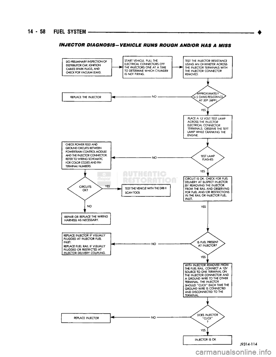
• INJECTOR DIAGNOSIS-VEHICLE RUNS ROUGH AND/OR HAS A
MISS
DO PRELIMINARY INSPECTION OF DISTRIBUTOR CAP,
IGNITION
CABLES
SPARK
PLUGS,
AND
CHECK
FOR VACUUM
LEAKS.
START VEHICLE, PULL THE
ELECTRICAL
CONNECTORS OFF
THE INJECTORS ONE AT A TIME
TO DETERMINE
WHICH
CYLINDER
IS
NOT FIRING.
REPLACE
THE INJECTOR -NO •
CHECK
POWER FEED AND
GROUND CIRCUITS BETWEEN POWERTRAIN CONTROL MODULE
AND THE INJECTOR CONNECTOR.
REFER
TO WIRING SCHEMATIC
FOR COLOR CODES AND PIN
TERMINAL NUMBERS. - NO-
YES
TEST THE VEHICLE
WITH
THE DRB II
SCAN
TOOL
NO
REPAIR
OR REPLACE THE WIRING
HARNESS
AS NECESSARY.
REPLACE
INJECTOR IF VISUALLY
PLUGGED
AT INJECTOR FUEL INLET.
REPLACE
FUEL RAIL IF VISUALLY
PLUGGED
OR RESTRICTED AT INJECTOR DELIVERY COUPLING. -NO
REPLACE
INJECTOR •NO-TEST THE INJECTOR RESISTANCE
USING AN OHMMETER
ACROSS
THE INJECTOR TERMINALS
WITH
THE INJECTOR CONNECTOR
REMOVED.
PLACE
A 12
VOLT
TEST LAMP
ACROSS
THE INJECTOR
ELECTRICAL
CONNECTOR
TERMINALS.
OBSERVE THE TEST LAMP WHILE CRANKING THE
ENGINE.
CIRCUIT IS OK. CHECK FOR FUEL DELIVERY AT SUSPECT INJECTOR
BY
REMOVING THE INJECTOR FROM THE RAIL AND OBSERVING
FOR FUEL AND/OR RESTRICTIONS IN THE RAIL OR INJECTOR FUEL INLET.
WITH
INJECTOR REMOVED FROM
THE FUEL RAIL, CONNECT A 12V
SOURCE
TO ONE TERMINAL ON
THE INJECTOR CONNECTOR AND
A
GROUND WIRE TO THE OTHER
TERMINAL. THE INJECTOR SHOULD "CLICK" EACH TIME THE GROUND WIRE IS CONNECTED
AND DISCONNECTED TO THE TERMINAL.
J9314-114